Herunterladen Inhalt Inhalt Diese Seite drucken
Kessel Aqualift S XL Anleitung Für Einbau, Betrieb Und Wartung

Kessel Aqualift S XL Anleitung Für Einbau, Betrieb Und Wartung

Pumpstation
Inhaltsverzeichnis

Werbung

Verfügbare Sprachen
  • DE

Verfügbare Sprachen

  • DEUTSCH, seite 1
ANLEITUNG FÜR EINBAU, BETRIEB UND WARTUNG
Pumpstation Aqualift S XL / Aqualift F XL
zur nassen Aufstellung (mit Stangenführung)
Installation
der Anlage wurde durchgeführt von Ihrem Fachbetrieb:
Name/Unterschrift
Stand 2018/07
Inbetriebnahme
Datum
Einweisung
Ort
D
GB
F
NL
PL
Produktvorteile
Für fäkalienhaltiges und
fäkalienfreies Abwasser
Großes Nutzvolumen
Einfache und schnelle
Montage
Geringes Gewicht
Hohe Sicherheit durch
Beständigkeit gegen
aggressive Medien
Grundwasserbeständig
bis 3 m
Stempel Fachbetrieb
1-34
35-68
69-102
I
103-136
137-170
171-208
Sach-Nr. 010-992

Werbung

Inhaltsverzeichnis
loading

Inhaltszusammenfassung für Kessel Aqualift S XL

  • Seite 1 ANLEITUNG FÜR EINBAU, BETRIEB UND WARTUNG 1-34 Pumpstation Aqualift S XL / Aqualift F XL 35-68 zur nassen Aufstellung (mit Stangenführung) 69-102 103-136 137-170 171-208 Produktvorteile Für fäkalienhaltiges und fäkalienfreies Abwasser Großes Nutzvolumen Einfache und schnelle Montage Geringes Gewicht Hohe Sicherheit durch Beständigkeit gegen...
  • Seite 2: Inhaltsverzeichnis

    Inhaltsverzeichnis Einleitung Produktbeschreibung ....................... 4 Allgemeine Hinweise zu dieser Betriebs- und Wartungsanleitung ........5 Funktionsprinzip ....................... 5 Produktbeschreibung Typenschild ........................6 Lieferumfang (Palettenaufteilung) ..................6 Lieferumfang (Kleinteilepaket) ..................7 Baugruppen und Funktionsmerkmale ................8 Sicherheit Bestimmungsgemäße Verwendung .................. 10 Personalauswahl und -qualifikation .................. 10 Organisatorische Sicherheits-Maßnahmen ..............
  • Seite 3 Pumpen von Hand ansteuern ................... 21 Absperrschieber betätigen ....................22 Wartung Sicherheitshinweise für die Wartung ................23 Wartungsintervalle ......................23 Wartungsvorbereitung ...................... 24 Wartungstätigkeiten ......................24 6.4.1 Pumpstation reinigen ......................24 6.4.2 Spülen der Druckleitung ....................28 6.4.3 Batterie im Schaltgerät erneuern ..................28 Problembehebung Technische Daten Pumpen (STZ) ........................
  • Seite 4: Einleitung

    Varianten Die KESSEL-Pumpstationen der Baureihe XL zur nassen Aufstellung sind in den Varianten Aqualift F XL und Aqualift S XL erhältlich. Die Varianten Mono und Duo entsprechen der Bestückung mit einer oder zwei Pumpen. Der Aufbau und die Verrohrung beider Varianten sind symmetrisch ausgelegt, um eine nachträgliche Umrüstung (Mono zu...
  • Seite 5: Allgemeine Hinweise Zu Dieser Betriebs- Und Wartungsanleitung

    Einleitung Allgemeine Hinweise zu dieser Betriebs- und Wartungsanleitung Verwendete Symbole und Legenden <1> Hinweis im Text auf eine Legendennummer in einer Abbildung Bezug auf eine Abbildung • Arbeitsschritt Arbeitsschritt in nummerierter Reihenfolge – Aufzählung Kursiv Kursive Schriftdarstellung: Bezug zu einem Abschnitt / Punkt im Steuerungs-Menü VORSICHT: Warnt vor einer Gefährdung von Personen und Material.
  • Seite 6: Produktbeschreibung

    Produktbeschreibung Produktbeschreibung Typenschild Abb. [3] Informationen auf dem Typenschild Bezeichnung der Anlage Artikelnummer Anschlussspannung und Anschlussfrequenz, Stromaufnahmebereich Maximaler Förderstrom / Förderhöhe Schutzart (IP) + Betriebsart Seriennummer QR-Code Revisionsstand der Hardware Lieferumfang (Palettenaufteilung) Abb. [4] Technikmodul (Palette 1) Pumpen und Kleinteile (Palette 2) 010-992 6 / 208 2018/07...
  • Seite 7: Lieferumfang (Kleinteilepaket)

    Produktbeschreibung Lieferumfang (Kleinteilepaket) Abb. [5] Pumpenkralle Niveauerfassung (Pegelsonde) Schaltgerät Dokumente (EBA, Konformitätserklärung...) Pumpen 010-992 2018/07 7 / 208...
  • Seite 8: Baugruppen Und Funktionsmerkmale

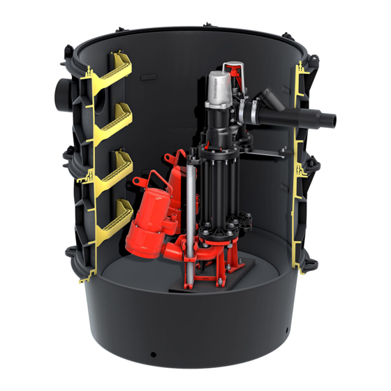
    Produktbeschreibung Baugruppen und Funktionsmerkmale Abb. [6] Abwasserpumpe Rückflussverhinderer mit Anlüftevorrichtung Druckleitungsanschluss DN 50 / DN 80 Spülanschluss 1 1/2“ IG Anbohrfläche für Entlüftungsleitung DN 100 Steighilfen Anbohrfläche für Kabelleerrohr Zulauf Niveauerfassung (Pegelsonde) Schachtmodul Technikmodul Fußkrümmer Absperrschieber aus Kunststoff 010-992 8 / 208 2018/07...
  • Seite 9 Produktbeschreibung Abb. [7] Abwasserpumpe Rückflussverhinderer mit Anlüftevorrichtung Druckleitungsanschluss DN 80 Spülanschluss 1 1/2“ IG Anbohrfläche für Entlüftungsleitung DN 100 Steighilfen Anbohrfläche für Kabelleerrohr Zulauf Niveauerfassung (Pegelsonde) Schachtmodul Technikmodul Fußkrümmer Absperrventil aus Gusseisen 010-992 2018/07 9 / 208...
  • Seite 10: Sicherheit

    Rückstauebene im Sinne der EN 12050-2. Nationale Bestimmungen für den Einsatz von fäkalienhaltigem oder fäkalienfreiem Abwasser können in bestimmten Ländern abweichen. Die Firma KESSEL empfiehlt auch in Ländern mit abweichenden Regelungen aufgrund höherer Betriebssicherheit die vorgesehene Verwendung beizubehalten. Ein Einsatz in explosionsgefährdeter Umgebung ist ausschließlich dann zulässig, wenn die Pumpstation in der dafür vorgesehenen Konfiguration (ATEX-Zertifiziert) ist.
  • Seite 11: Organisatorische Sicherheits-Maßnahmen

    Sicherheit Organisatorische Sicherheits-Maßnahmen Die Betriebs- und Wartungsanleitung ist stets verfügbar zu halten. Einbau- und Betriebsanleitung der mitgelieferten Komponenten beachten (z. B. Technikmodul, Schaltgerät). Betriebs- und Wartungsanleitungen verbundener Anlagen beachten (z. B. Fett- oder Leichtflüssigkeitsabscheider). Allgemeine Sicherheitshinweise WARNUNG! Potentiell explosives Gasgemisch im Abwasserbehälter Bei unzureichender Be- und Entlüftung der Anlage können Ausdünstungen des Abwassers (z.
  • Seite 12 Sicherheit Betrieb in EX-Zone Hinweise zum Explosionsschutz: Bei Aufstellung von Aggregaten in explosionsgefährdeten Bereichen sind die Bestimmungen der Richtlinie RL 2014/34/EU zu beachten. Die Motoren können an elektrische Niederspannungsnetze mit Netzspannungen und Spannungstoleranzen von max. +-5 % und Frequenztoleranzen von +-2 % angeschlossen werden. Bitte beachten Sie die beigelegte Bedienungsanleitung der Pumpe.
  • Seite 13: Montage

    Montage Montage Gefahr durch giftige und gesundheitsgefährdende Dämpfe, Gase und Stoffe (z. B. Bakterien, Viren). Alle an der Pumpstation notwendige Arbeiten ausschließlich durch Fachpersonal (Siehe 3.2) durchführen. Vor einem Öffnen von Gehäuseabdeckungen, Steckern und Kabeln (auch an den potentialfreien Kontakten) sind diese spannungsfrei zu machen. Arbeiten an elektrischen Bauteilen dürfen nur von Fachpersonal (siehe 3.2) durchgeführt werden.
  • Seite 14: Anschlussstück Der Pumpe Anbringen

    Montage Anschlussstück der Pumpe anbringen 4.1.1 Pumpe mit Gewindeanschluss • Pumpenkralle <2> an Pumpe aufschrauben und mit Madenschraube <3> sichern. • Sicherstellen, dass die Dichtung <1> in Pumpenkralle <2> eingelegt ist. Abb. [9] 4.1.2 Pumpe mit Flanschanschluss • Sicherstellen, dass Flachdichtung <1> in Pumpenkralle <2> eingelegt ist.
  • Seite 15: Pumpe Einlassen Und Befestigen

    Montage Pumpe einlassen und befestigen • Kette (Zubehör) an Pumpe befestigen • Eine zum Gewicht der Pumpe geeignete Hebehilfe bereitstellen • Pumpe <1> in den Schacht einbringen. Dazu diese mit der Hebehilfe an der Kette <2> langsam herunterlassen, unten am Führungsrohr <3> einhängen und bis zum Schachtboden herunterlassen.
  • Seite 16: Niveauerfassung Montieren

    Montage Niveauerfassung montieren Pegelsonde • Schutzklappe von Druckmembran abziehen. • Sicherstellen, dass der Abstand <L> zwischen Muffenstopfen <3> und Sondenspitze <4> 630 mm beträgt • Pegelsonde <1> bis zum Anschlag in das Aufnahmerohr <2> einführen Abb. [12] Abbildung <13> zeigt Pumpstation mit Gussarmatur Abb. [13] 010-992 16 / 208 2018/07...
  • Seite 17: Typenschild Anbringen

    Ser. Nr. xxxxxxxxx RevStd.: x.x MM/JJ DIN-EN 1 Pumpstation Aqualift F/S XL xxxxx www.kessel.de/info xxxxxxxxxx Abb. [14] Hakenschraube und Kette befestigen • Loch (Ø 4 mm) bohren und Hakenschraube eindrehen <1>. • Kette einhaken und Kabel für Pegelsonde einhängen <2>.
  • Seite 18: Elektrische Anschlüsse Und Anschluss Niveauerfassung Herstellen

    Montage Elektrische Anschlüsse und Anschluss Niveauerfassung herstellen Sicherstellen, dass das Schaltgerät während den Montagearbeiten von der Spannungsversorgung getrennt ist. Gefahr von elektrischem Schlag bei unbeabsichtigten Berühren abgeschraubter Steckverbindungen (z.B. durch Kinder). Sicherstellen, dass alle elektrischen Anschlussverbindungen - sofern vorhanden - wie abgebildet befestigt werden (Anzugsmoment).
  • Seite 19: Funktionskontrolle

    – Sofern vorhanden, prüfen ob das Schaltgerät initialisiert wird – Pumpe läuft selbsttätig an – Pumpe pumpt bis zu Ausschaltniveau (Pumpenkopf wieder sichtbar) ab – Pumpe schaltet selbsttätig ab • Schaltgerät auf Fehler/Alarmmeldungen prüfen. Bei Fehler/Alarmmeldungen KESSEL-Kundendienst kontaktieren 010-992 2018/07 19 / 208...
  • Seite 20: Betrieb

    Betrieb Betrieb Alle Rückflussverhinderer müssen während dem Betrieb funktionstüchtig sein, siehe <2> auf Abb. [6], Seite 10 Der Absperrschieber muss im Betriebsfall immer geöffnet, und mit Sicherheitsbügel verriegelt sein. Einschalten Hauptschalter <28> in Position I (ON) drehen, nach erfolgreichem Systemtest erscheinen im Display <29> die Anlageninformationen und die grüne LED <30>...
  • Seite 21: Alarm Quittieren

    Betrieb Alarm quittieren Ist ein Zustand aufgetreten, der einen Alarm auslöste (z.B. Fehler an einer Pumpe, Pegelstand des Abwassers erreichte Alarm-Niveau) leuchtet die Alarm-LED <21>. Im Display wird ggf. eine Fehlermeldung im Klartext ausgegeben. Nach der Beseitigung der Ursache für den Alarm, kann der Alarm durch Drücken der Taste <69> quittiert werden.
  • Seite 22: Absperrschieber Betätigen

    Betrieb Absperrschieber betätigen Sicherstellen, dass Absperrventil im Betriebszustand in offener Position ist! Abb. [18] Absperrschieber schließen • Schutzkappe <4> abstecken • 1. Sicherheitsbügel entriegeln 2. Drehhebel 45° nach links drehen 3. Absperrschieber nach unten drücken • Absperrschieber 45° nach rechts drehen (C), er ist geschlossen und verriegelt Absperrschieber öffnen •...
  • Seite 23: Wartung

    Wartung Wartung Sicherheitshinweise für die Wartung Gefahr durch giftige und gesundheitsgefährdende Dämpfe, Gase und Stoffe (z. B. Bakterien, Viren). Befindet sich die Pumpstation in einem Schacht, sind darin notwendige Arbeiten ausschließlich durch Fachpersonal (Siehe 3.2) durchzuführen. Vor einem Öffnen von Gehäuseabdeckungen, Steckern und Kabeln (auch an den potentialfreien Kontakten) sind diese spannungsfrei zu machen.
  • Seite 24: Wartungsvorbereitung

    Wartung Wartungsvorbereitung – Sicherstellen, dass der Zulauf zur Pumpstation während der Wartung unbenutzt bleibt. – Sicherstellen, dass die Pumpstation während der Wartungsarbeiten nicht unbeabsichtigt eingeschaltet werden kann. Das gilt im Besonderen, wenn sich das Schaltgerät in einem anderen Raum als der Anlagenbehälter befindet.
  • Seite 25 Wartung Pegelsonde reinigen • Pegelsonde aus dem Aufnahmerohr <27> herausziehen • Pegelsonde reinigen und sicherstellen dass das Innere des Aufnahmerohrs <27> frei von Verschmutzungen ist • Pegelsonde wieder in das Aufnahmerohr <27> einsetzen und sicherstellen dass das Maß <L>, siehe Kapitel 4.2 hergestellt ist Abb.
  • Seite 26 Wartung Reinigung und Kontrolle Rückflussverhinderer (Kunststoffarmatur) Der Rückflussverhinder wird bei häufigem Betrieb stark verschleißt. Wir empfehlen Kontrolle und regelmäßigen Tausch um eine erhöhte Betriebssicherheit zu gewährleisten. Abb. [23] Anlüftvorrichtung <24A> am Rückflussverhinderer <25> in waagerechte Position bringen, das zurückgestaute Abwasser kann vom Druckrohr in den Anlagenbehälter zurücklaufen •...
  • Seite 27 Wartung Reinigung und Kontrolle Rückflussverhinderer (Gussarmatur) Abb. [24] Rückflussverhinderer ausbauen: • Schrauben (1) lösen • Deckel (2) abnehmen • Rückflussverhinderer (3) herausziehen • Rückflussverhinderer reinigen und auf Beschädigungen überprüfen • Teile in umgekehrter Reihenfolge wieder montieren Abb. [25] • Abwasserpumpe(n) wieder montieren (siehe Kapitel 4.1) •...
  • Seite 28: Spülen Der Druckleitung

    Wartung 6.4.2 Spülen der Druckleitung Bei besonders langen Druckleitungen sollte nach dem Reinigen der Pumpstation separat die Druckleitung gespült werden um Ablagerungen in der Druckleitung entgegenzuwirken. • Über den Spülanschluss <14> die Druckleitung spülen Abb. [26] 6.4.3 Batterie im Schaltgerät erneuern •...
  • Seite 29: Problembehebung

    Problembehebung Problembehebung Alle Arbeiten, die über die im Kapitel Betrieb beschriebenen Tätigkeiten hinausgehen, dürfen nur von Fachpersonal (siehe 3.2) durchgeführt werden. • Hinweise wie unter 6.1 beschrieben beachten und ggf. durchführen • Beachten Sie die Einbau- und Bedienungsanleitung des Schaltgerätes. Fehler Mögliche Ursache Abhilfemaßnahme / Kapitel Batteriefehler...
  • Seite 30: Technische Daten

    Technische Daten Technische Daten Pumpen (STZ) STZ* Pumpe 1300 2500 3700 Gewicht [kg] Leistung P1 Leistung P2 Drehzahl [u/min] 2900 Betriebsspannung [V] 400V / 50 Hz Nennstrom [A] Förderleistung max [m³/h] Förderhöhe max. [m] Förderguttemperatur max. [°C] Schutzart IP 68 (20 m/48 h) Schutzklasse Motorschutz extern über Schaltgerät...
  • Seite 31 Technische Daten STZ* Pumpe 4400 5200 7500 11000 Gewicht [kg] Leistung P1 [kW] 11,0 Leistung P2 Drehzahl [u/min] 2840 2900 Betriebsspannung [V] 400V / 50 Hz Nennstrom [A] 7,5 A 8,7 A 13,0 A 18,8 A Förderleistung max [m³/h] 21,3 m³/h 21,3 m³/h 30,7 m³/h 30,6 m³/h...
  • Seite 32 Technische Daten GTK* Pumpe 1300 2600 3700 5200 Gewicht [kg] Leistung P1 Leistung P2 Drehzahl [u/min] 2900 Betriebsspannung [V] 400 V / 50 Hz Nennstrom [A] Förderleistung max [m³/h] 51,6 Förderhöhe max. [m] 12,4 19,6 23,5 31,6 Förderguttemperatur max. [°C] Schutzart IP 68 (20 m/48 h) Schutzklasse...
  • Seite 33: Kennlinie

    Technische Daten Kennlinie H [ m ] STZ 1300-S1 STZ 2500-S1 STZ 3700-S1 STZ 4400-S1 STZ 5200-S1 STZ 7500-S1 STZ 11000-S1 Q [ m /h ] Abb. [27] H [ m ] GTF 5200 GTF 4000 GTF 4000 GTF 2600 GTF 2600 GTF 1600 Q [ m...
  • Seite 34: Anschlüsse

    Ausschaltniveau Aus 2* [mm] 340 (500) 280 (500) * Der Wert in Klammern gilt für Variante mit Gussarmatur ** nur bei Duoanlage Schaltniveaus gelten für Automatikbetrieb S3 Abb. [30] Abmessungen, Volumen Siehe Einbauanleitung KESSEL Technikschacht LW1000 (010-701) 010-992 34 / 208 2018/07...
  • Seite 35 INSTRUCTIONS FOR INSTALLATION, OPERATION AND MAINTENANCE Aqualift S XL / Aqualift F XL pumping station for wet installation (with rod guide) Product advantages For wastewater with and without sewage Large useful volume Simple and fast installation Low weight High safety level due to...
  • Seite 36 Table of Contents Introduction Product description ......................38 General information on these operating and maintenance instructions ......39 How it works ........................39 Product Description Type plate ......................... 40 Scope of delivery (pallet allocation) .................. 40 Scope of delivery (small parts package) ................41 Assemblies and functional characteristics ...............
  • Seite 37 Maintenance Maintenance safety instructions ..................57 Maintenance intervals ....................... 57 Maintenance preparation ....................58 Maintenance tasks ......................58 6.4.1 Cleaning the pumping station ................... 58 6.4.2 Flushing the pressure pipe ....................62 6.4.3 Replacing the battery in the control unit ................62 Troubleshooting Technical data Pumps ..........................
  • Seite 38: Introduction

    Variants The KESSEL pumping stations of the XL series for wet installation are available in the variants Aqualift F XL and Aqualift S XL. The Mono and Duo variants are equipped with one or two pumps respectively. The layout and piping of the two variants is designed symmetrically in order to make later conversion possible (Mono to Duo and vice versa).
  • Seite 39: General Information On These Operating And Maintenance Instructions

    Introduction General information on these operating and maintenance instructions Symbols and keys used <1> Reference in the text to a key number in an illustration Reference to an illustration (Figure) • Work step Work step in numbered order – List Italics Italic type: Reference to a section / item in the control menu CAUTION: Warns of a hazard for persons and material.
  • Seite 40: Product Description

    Pumpstation Aqualift F/S XL xxxxx xxxxx xxxV xxHz x,xA x,xkW xxm³/h S3 xx% ED IP xx (xmWS/xh) Ser. Nr. xxxxxxxxx www.kessel.de/info RevStd.: x.x MM/JJ DIN-EN 1 xxxxxxxxxx Ill. [3] Information on the type plate Name of the system Article number...
  • Seite 41: Scope Of Delivery (Small Parts Package)

    Product Description Scope of delivery (small parts package) Ill. [5] Pump claw Level detection (level sensor) Control unit Documents (installation instructions, Declaration of Conformity, ...) Pumps 010-992 2018/07 41 / 208...
  • Seite 42: Assemblies And Functional Characteristics

    Product Description Assemblies and functional characteristics Ill. [6] Wastewater pump Backwater preventer with ventilation device Pressure pipe connection DN50 / DN80 Flushing connection 1 1/2“ inner thread Tapping area for ventilation pipe DN100 Access steps Tapping area for reserve conduit Inlet Level detection (level sensor) Technical module...
  • Seite 43 Product Description Ill. [7] Wastewater pump Backwater preventer with ventilation device Pressure pipe connection DN80 Flushing connection 1 1/2“ inner thread Tapping area for ventilation pipe DN100 Access steps Tapping area for reserve conduit Inlet Level detection (level sensor) Technical module Chamber module Gate valve Shut-off valve made of cast iron...
  • Seite 44: Safety

    12050-2. National regulations for the use of wastewater with or without sewage can vary in different countries. On account of the greater operational safety, KESSEL recommends observing the designated use even in countries with deviating regulations. Use in a potentially explosive environment is only permissible when the pumping station has the respective configuration (ATEX-certified).
  • Seite 45: Organisational Safety Measures

    Safety Organisational safety measures The operating and maintenance instructions must be kept available at all times. Heed the installation and operating instructions for the enclosed components (e. g. technical module, control unit). Heed the operating and maintenance instructions of connected systems (e. g. grease separators or volatile liquid traps). General safety notes WARNING! Potentially explosive gas mixture in the wastewater container If the system is not sufficiently aerated and ventilated, vapours from the wastewater (e.
  • Seite 46 Safety Operation in EX zone Instructions related to explosion protection When units are set up in potentially explosive areas, the requirements of the guideline 2014/34/EU must be heeded. The motors can be connected to electrical low- voltage networks with supply voltages and voltage tolerances of max. +-5% and frequency tolerances of +-2%.
  • Seite 47: Installation

    Installation Installation Hazard due to toxic and harmful fumes, gases and substances (e. g. bacteria, viruses). Assign skilled personnel (see 3.2) to carry out any necessary work on the pumping station. Before opening housing covers, plugs and cables (including those on floating contacts) they must be safely isolated from the power supply (de-energised).
  • Seite 48: Attach Pump Connection Flange

    Installation Attach pump connection flange 4.1.1 Pump with threaded connection • Screw the pump claw <2> to the pump and secure using the grub screw <3> • Ensure that sealing gasket <1> is inserted into claw <2>. • Fix the chain (accessory) to the pump Ill.
  • Seite 49: Mount The Pump Flush And Fasten In Place

    Installation Mount the pump flush and fasten in place • Provide lifting equipment suitable for the weight of the pump • Place the pump <1> in the chamber. For this, lower the pump slowly on the chain <2> using the lifting equipment, connect it to the guide pipe <3>...
  • Seite 50: Installing The Level Detection

    Installation Installing the level detection Level sensor • Pull safety cap from pressure diaphraghm. • Make sure that the distance <L> between the blind plug <3> and the sensor tip <4> is 630 mm • Insert the level sensor <1> into the retainer tube <2> as far as it will go Ill.
  • Seite 51: Attaching The Type Plate

    MM/JJ DIN-EN 1 Pumpstation from outside. Aqualift F/S XL xxxxx www.kessel.de/info xxxxxxxxxx Ill. [14] Attaching the hook bolt and chain • Drill hole (Ø 4 mm) into the middle of the upper section. Screw in clip bolt <1>. • Hook chain into clip bolt and insert cable for level sensor <2>.
  • Seite 52: Establishing Electrical Connections And Level Detection Connection

    Installation Establishing electrical connections and level detection connection Make sure that the control unit is disconnected from the power supply during installation work. Electric shock hazard caused by unintentional touching (e.g. by children) of unscrewed plug-in connections. Make sure that all electrical connections – if present – are fastened as shown (tightening torque).
  • Seite 53: Functional Check

    – The pump pumps out water until the switching-off level is reached (pump head visible once again) – Pump switches off automatically • Check the control unit for errors/alarm signals. In the event of errors/alarm signals, contact KESSEL Customer Services...
  • Seite 54: Operation

    Operation Operation The backwater preventers must be functional during operation, see <2> in Fig. [6], page 10 During operation, the shut-off valve must always be opened and locked with the safety bracket. Switching on Turn the main switch <28> to position I (ON), following a successful system test the system information appears in the display <29>...
  • Seite 55: Acknowledging The Alarm

    Operation Acknowledging the alarm If a state occurs which triggers an alarm (e.g. fault on a pump, level of the wastewater has reached the alarm level), the alarm LED <21> will light up. A plain text fault message may be shown on the display. After the cause of the alarm has been eliminated, the alarm can be acknowledged by pressing key <69>.
  • Seite 56: Actuating The Shut-Off Valve

    Operation Actuating the shut-off valve Make sure that the shut-off valve is in the open position in operating state. Ill. [18] Close the shut-off valve • Remove the protective cap <4> • 1. Release the safety bracket 2. Turn the rotary lever 45° anti-clockwise 3.
  • Seite 57: Maintenance

    Maintenance Maintenance Maintenance safety instructions Hazard due to toxic and harmful fumes, gases and substances (e. g. bacteria, viruses). If the pumping station is located in a chamber, any necessary work must always be carried out by skilled personnel only (see 3.2). Before opening housing covers, plugs and cables (including those on floating contacts) they must be safely isolated from the power supply (de-energised).
  • Seite 58: Maintenance Preparation

    Maintenance Maintenance preparation – Make sure that the inlet to the pumping station is not used during maintenance work. – Make sure that the pumping station cannot be switched on accidentally during maintenance work. This applies in particular if the control unit is in a different room to the system tank. Maintenance tasks 6.4.1 Cleaning the pumping station •...
  • Seite 59 Maintenance Cleaning the level sensor • Pull the level sensor out of the retainer tube <27> • Clean the level sensor and make sure that the inside of the retainer tube <27> is free of soiling • Insert the level sensor back in the retainer tube <27> and ensure that the dimension <L>, see chapter 4.2 is set up Ill.
  • Seite 60 Maintenance Cleaning and checking the backwater preventer (Polymer fitting) Notice: The backwater preventer is subject to wear when in frequent use. We recommend checks and periodic exchange of the backwater preventer to ensure improved dependability. Ill. [22] • Bring the ventilation device <24A> on the backwater preventer <25> into a horizontal position, the dammed up wastewater can flow back from the pressure pipe into the system tank •...
  • Seite 61 Maintenance Cleaning and checking the backwater preventer (Cast iron fitting) Ill. [24] Remove backwater preventer: • Undo the screws (1) • Take the cover (2) off • Pull the backwater preventer (3) out • Clean the backwater preventer and check for damage •...
  • Seite 62: Flushing The Pressure Pipe

    Maintenance 6.4.2 Flushing the pressure pipe Where pressure pipes are especially long, the pressure pipe should be flushed separately after the pumping station has been cleaned in order to prevent deposits lodging in the pressure pipe. • Flush the pressure pipe via the flushing connection <14> Ill.
  • Seite 63: Troubleshooting

    Troubleshooting Troubleshooting All work exceeding the activities described in the Operation chapter may only be carried out by skilled personnel (see 3.2). • Follow the instructions described in 5.1 and carry out if necessary Error Possible cause Remedial measure / Chapter Battery fault Battery is missing, is defective or voltage Check battery connection, if necessary...
  • Seite 64: Technical Data

    Technical data Technical data Pumps STZ* Pump 1300 2500 3700 Weight [kg] Power P1 Power P2 Speed [rpm] 2900 Operating voltage [V] 400V / 50Hz Nominal current [A] Max. delivery rate [m³/h] Max. delivery head [m] Max. temperature of pumped material [°C] Degree of protection IP68 (20m WC/48 h) Protection class...
  • Seite 65 Technical data STZ* Pump 4400 5200 7500 11000 Weight [kg] Power P1 11,0 Power P2 Speed [rpm] 2840 2900 Operating voltage [V] 400V / 50 Hz Nominal current [A] 7,5 A 8,7 A 13,0 A 18,8 A Max. delivery rate [m³/h] 21,3 m³/h 21,3 m³/h 30,7 m³/h...
  • Seite 66 Technical data GTK* Pump 1300 2600 3700 5200 Weight [kg] Power P1 Power P2 Speed [rpm] 2900 Operating voltage [V] 400V / 50Hz Nominal current [A] Max. delivery rate [m³/h] 51,6 Max. delivery head [m] 12.4 19.6 23.5 31,6 Max. temperature of pumped material [°C] Degree of protection IP68 (20m WC/48 h)
  • Seite 67: Characteristic Curves

    Technical data Characteristic curves H [ m ] STZ 1300-S1 STZ 2500-S1 STZ 3700-S1 STZ 4400-S1 STZ 5200-S1 STZ 7500-S1 STZ 11000-S1 Q [ m /h ] Ill. [27] H [ m ] GTF 5200 GTF 4000 GTF 4000 GTF 2600 GTF 2600 GTF 1600 Q [ m...
  • Seite 68: Connections

    * The value in brackets applies for the variant with cast iron fitting ** for Duo system only The switching levels apply to automatic mode S3 Ill. [30] Dimensions, volume See installation instructions for KESSEL technical chamber LW1000 (010-701) 010-992 68 / 208 2018/07...
  • Seite 69 INSTRUCTIONS DE POSE, D‘UTILISATION ET DE MAINTENANCE Postes de pompage Aqualift S XL / Aqualift F XL pour pose immergée (avec tuyaux de guidage) Avantages du produit Pour eaux grises et eaux vannes Grand volume utile Montage simple et rapide Faible poids Sécurité...
  • Seite 70 Sommaire Introduction Description du produit ...................... 72 Informations d‘ordre général concernant les présentes instructions d‘utilisation et de maintenance ..................73 Principe de fonctionnement ....................73 Description du produit Plaque signalétique ......................74 Détail de livraison (répartition sur palettes) ............... 74 Détail de livraison (colis contenant les petits accessoires) ..........
  • Seite 71 Mise hors circuit ....................... 89 Commande manuelle des pompes ................... 89 Actionnement de la vanne d’arrêt ..................90 Maintenance Consignes de sécurité spécifiques à la maintenance ............91 Intervalles de maintenance ....................91 Préparation de la maintenance ..................92 Interventions de maintenance ..................92 6.4.1 Nettoyage du poste de pompage ..................
  • Seite 72: Introduction

    Chère cliente, Cher client, Nous vous félicitons de votre achat d‘un produit KESSEL. Ce produit sera certainement en mesure de répondre à toutes vos attentes. Nous vous souhaitons une mise en place sans faille et réussie. Nous tentons de maintenir un niveau de qualité aussi élevé que possible de nos produits et avons évidemment besoin de votre collaboration.
  • Seite 73: Informations D'ordre Général Concernant Les Présentes Instructions D'utilisation Et De Maintenance

    Introduction Informations d‘ordre général concernant les présentes instructions d‘utilisation et de maintenance Pictogrammes et légendes utilisés <1> Information dans le texte attirant l‘attention sur un numéro de légende dans une figure Renvoi à une figure • Étape opératoire Étape opératoire par ordre d‘apparition numéroté –...
  • Seite 74: Description Du Produit

    Pumpstation Aqualift F/S XL xxxxx xxxxx xxxV xxHz x,xA x,xkW xxm³/h S3 xx% ED IP xx (xmWS/xh) Ser. Nr. xxxxxxxxx www.kessel.de/info RevStd.: x.x MM/JJ DIN-EN 1 xxxxxxxxxx Fig. [3] Informations figurant sur la plaque signalétique Désignation du poste Référence Tension et fréquence d‘alimentation, puissance absorbée Débit maximal / hauteur de refoulement...
  • Seite 75: Détail De Livraison (Colis Contenant Les Petits Accessoires)

    Description du produit Détail de livraison (colis contenant les petits accessoires) Fig. [5] Griffe de pompe Détection du niveau (sonde de niveau) Gestionnaire Documents (instructions de pose et d‘utilisation, déclaration de conformité...) Pompes 010-992 2018/07 75 / 208...
  • Seite 76: Sous-Groupes Et Éléments Fonctionnels

    Description du produit Sous-groupes et éléments fonctionnels Fig. [6] Pompe d‘assainissement Anti retour avec dispositif de purge d’air Raccord pour conduite de refoulement DN50 / DN80 Raccord de rinçage 1 1/2“ IG Surface de perçage pour la conduite de purge d‘air DN100 Échelle d‘accès Surfaces de perçage pour le conduit de câbles...
  • Seite 77 Description du produit Fig. [7] Pompe d‘assainissement Anti retour avec dispositif de purge d’air Raccord pour conduite de refoulement DN80 Raccord de rinçage 1 1/2“ IG Surface de perçage pour la conduite de purge d‘air DN100 Échelle d‘accès Surfaces de perçage pour le conduit de câbles Entrée Détection du niveau (sonde de niveau) Module technique...
  • Seite 78: Sécurité

    Les dispositions spécifiques à l’emploi des eaux usées avec ou sans matières fécales peuvent varier suivant le pays d’utilisation. En vue de garantir une sécurité opérationnelle aussi élevée que possible, KESSEL recommande de respecter l’utilisation prévue, même dans des pays sujets à des réglementations divergentes.
  • Seite 79: Consignes De Sécurité Organisationnelles

    Sécurité Consignes de sécurité organisationnelles Les instructions d‘utilisation et de maintenance doivent être disponibles en permanence. Observer les instructions de pose et d’utilisation des composants fournis (p. ex. celles du module technique, du gestionnaire). Observer les instructions d‘utilisation et de maintenance des systèmes reliés (p. ex. celles du séparateur de graisse ou d‘effluents légers).
  • Seite 80 Sécurité Nuisances sonores Le poste de pompage risque de causer un niveau sonore élevé en fonctionnement. Portez un équipement de protection adéquat, au besoin, et prévoyez une insonorisation appropriée. Fonctionnement en zone ATEX Informations spécifiques à la protection antidéflagrante : Respecter les dispositions de la directive 2014/34/UE lors de la mise en place des groupes ou unités dans des zones à...
  • Seite 81: Montage

    Montage Montage Risque lié aux vapeurs, gaz et substances toxiques ou nuisible à la santé (p. ex. les bactéries, virus). Tous les travaux à effectuer sur un poste de pompage demeurent réservés au domaine de compétence exclusif de personnes qualifiées (voir 3.2). Débrancher impérativement les fiches d‘alimentation et câbles (y compris au niveau des contacts libres) avant d‘ouvrir les recouvrements ou caches des carters ou boîtiers.
  • Seite 82: Installer Le Raccord De La Pompe

    Montage Installer le raccord de la pompe 4.1.1 Pompe avec raccord à visser • Visser la griffe de pompe <2> à la pompe et la bloquer avec la vis sans tête <3> • Assurez-vous que le joint <1> est bien positionné dans son logement <2>...
  • Seite 83: Descendre La Pompe Et La Fixer

    Montage Descendre la pompe et la fixer • Prévoir un dispositif de levage approprié au poids de la pompe • Placer la pompe <1> dans le regard. Pour ce faire, descendre la pompe suspendue à la chaîne <2> du dispositif de levage, l’accrocher dans le bas du tube de guidage <3>...
  • Seite 84: Montage De La Détection Du Niveau

    Montage Montage de la détection du niveau Sonde de niveau • Retirer le couvercle de protection du capteur de pression. • S’assurer que l’écart <L> entre le bouchon de manchon <3> et la pointe de la sonde  <4> comporte 630 mm • Engager la sonde de niveau <1> jusqu’à la butée dans le tube de fixation <2>...
  • Seite 85: Installation De La Plaque Signalétique

    RevStd.: x.x MM/JJ DIN-EN 1 Pumpstation Aqualift F/S XL xxxxx www.kessel.de/info xxxxxxxxxx Fig. [14] Fixation de la vis à crochet et de la chaîne • Trou (Ø 4 mm) centre de forage dans la section supérieure, puis vis à crochet <1>.
  • Seite 86: Réalisation Des Connexions Électriques Et Raccordement De La Détection Du Niveau

    Montage Réalisation des connexions électriques et raccordement de la détection du niveau S‘assurer que le gestionnaire a été coupé de l‘alimentation en tension pendant les travaux de montage. Risque de coups électriques en cas de contact par inadvertance avec des fiches de raccordement dévissées (p.
  • Seite 87: Contrôle Fonctionnel

    – La pompe refoule l’eau jusqu’au niveau de déconnexion (la tête de pompe est à nouveau visible) – La pompe se déconnecte automatiquement • Vérifier l’absence de messages d’erreur ou d‘alarme du gestionnaire. Contacter le service après vente KESSEL en cas de messages d’erreur ou d‘alarme 010-992 2018/07...
  • Seite 88: Service

    Service Service Tous les anti retours doivent demeurer aptes au fonctionnement pendant le service, voir <2> de la Fig. [6], page 10 En service, la vanne d‘arrêt doit toujours demeurer ouverte, verrouillée avec capuchon de protection  Mise en circuit Tourner l‘interrupteur principal <28> en position I (ON), après un test réussi du système, l‘écran <29>...
  • Seite 89: Acquittement De L'alarme

    Service Acquittement de l‘alarme Un état qui a déclenché une alarme (p. ex. une erreur concernant une pompe, l‘atteinte du niveau d‘alarme des eaux usées), la LED d‘alarme <21> brille. L‘écran affiche éventuellement un message d‘erreur libellé en clair. Éliminer la cause de l‘alarme, puis acquitter l‘alarme en appuyant sur la touche <69>. –...
  • Seite 90: Actionnement De La Vanne D'arrêt

    Service Actionnement de la vanne d’arrêt S‘assurer que la vanne d’arrêt est en position ouverte tant qu’elle est en fonctionnement. Fig. [18] Fermeture de la vanne d’arrêt • Retirer le capuchon de protection <4> • 1. Déverrouiller l’étrier de sûreté 2. Tourner le levier de 45° vers la gauche 3.
  • Seite 91: Maintenance

    Maintenance Maintenance Consignes de sécurité spécifiques à la maintenance Risque lié aux vapeurs, gaz et substances toxiques ou nuisible à la santé (p. ex. les bactéries, virus). Les travaux à effectuer sur un poste de pompage logé dans un regard demeurent réservés au domaine de compétence exclusif de personnes qualifiées (voir 3.2).
  • Seite 92: Préparation De La Maintenance

    Maintenance Préparation de la maintenance – S‘assurer que l‘entrée du poste de pompage ne sera pas utilisée pendant la maintenance. – S‘assurer qu‘on ne puisse pas mettre le poste de pompage en circuit par inadvertance pendant les interventions de maintenance. Cette disposition possède une importance particulière si le gestionnaire se situe dans une autre pièce que le bac collecteur.
  • Seite 93 Maintenance Nettoyage de la sonde de niveau • Extraire la sonde de niveau du tube de fixation <27> • Nettoyer la sonde de niveau et s’assurer de l’absence d’encrassements à l’intérieur du tube de fixation <27> • Replacer la sonde de niveau dans le tube de fixation <27> et s’assurer du respect de la dimension <L, voir chapitre 4.2 >...
  • Seite 94 Maintenance Nettoyage et contrôle de l’anti retour (Robinetterie en plastique) Astuce, le clapet anti retour peut s’user en cas de fonctionnement permanent. Nous recommendons de controler regulierement et de le changer afin d’assurer une protection optimale. Fig. [22] • Amener le dispositif de purge d‘air <24A> de l‘anti retour <25> en position horizontale ; les eaux usées refoulées peuvent refluer du tuyau de refoulement dans le bac collecteur •...
  • Seite 95 Maintenance Nettoyage et contrôle de l’anti retour (Robinetterie en fonte) Fig. [24] Démonter l’anti-retour : • Détacher les vis (1) • Enlever le couvercle (2) • Extraire l’anti-retour (3) • Nettoyer l’anti-retour et vérifier l’absence de détériorations • Remonter les pièces dans le sens inverse du démontage Fig.
  • Seite 96: Rinçage De La Conduite De Refoulement

    Maintenance 6.4.2 Rinçage de la conduite de refoulement Le rinçage séparé de la conduite de refoulement est recommandé après le nettoyage du poste de pompage pour parer aux dépôts dans des conduites de refoulement d’une longueur exceptionnelle. • Rincer la conduite de refoulement via le raccord de rinçage <14> Fig.
  • Seite 97: Dépannages

    Dépannages Dépannages Toutes les interventions et activités non décrites dans le chapitre du service demeurent réservées au domaine de compétence de personnes qualifiées (voir 3.2). • Tenir compte des observations décrites suivant 5.1 et les exécuter si nécessaire Défaut Cause possible Remède / chapitre Défaut de la batterie Batterie manque, est défectueuse ou...
  • Seite 98: Caractéristiques Techniques

    Caractéristiques techniques Caractéristiques techniques Pompes STZ* Pompe 1300 2500 3700 Poids (kg) Puissance P1 Puissance P2 Régime [tr/min] 2900 Tension de service [V] 400V / 50Hz Courant nominal [A] Débit maxi de la pompe [m³/h] Hauteur de relevage maxi [m] Température du fluide refoulé maxi [°C] Type de protection IP68 (20m colonne d’eau / 48 h) Catégorie de protection...
  • Seite 99 Caractéristiques techniques STZ* Pompe 4400 5200 7500 11000 Poids (kg) Puissance P1 11,0 Puissance P2 Régime [tr/min] 2840 2900 Tension de service [V] 400V / 50 Hz Courant nominal [A] 7,5 A 8,7 A 13,0 A 18,8 A Débit maxi de la pompe [m³/h] 21,3 m³/h 21,3 m³/h 30,7 m³/h...
  • Seite 100 Caractéristiques techniques GTK* Pompe 1300 2600 3700 5200 Poids (kg) Puissance P1 Puissance P2 Régime [tr/min] 2900 Tension de service [V] 400V / 50Hz Courant nominal [A] Débit maxi de la pompe [m³/h] 51,6 Hauteur de relevage maxi [m] 12,4 19,6 23,5 31,6 Température du fluide refoulé...
  • Seite 101: Courbes Caractéristiques

    Caractéristiques techniques Courbes caractéristiques H [ m ] STZ 1300-S1 STZ 2500-S1 STZ 3700-S1 STZ 4400-S1 STZ 5200-S1 STZ 7500-S1 STZ 11000-S1 Q [ m /h ] Fig. [27] H [ m ] GTF 5200 GTF 4000 GTF 4000 GTF 2600 GTF 2600 GTF 1600 Q [ m...
  • Seite 102: Raccords

    * La valeur entre parenthèses est valable pour la variante avec la robinetterie en fonte ** uniquement pour version Duo Les niveaux de commutation s‘appliquent au mode automatique S3 Dimensions, volume Voir les instructions de pose du regard technique KESSEL LW1000 (010-701) 010-992 102 / 208 2018/07...
  • Seite 103 ISTRUZIONI PER L‘INSTALLAZIONE, IL FUNZIONAMENTO E LA MANUTENZIONE Stazione di pompaggio Aqualift S XL / Aqualift F XL per l’installazione in umido (con guida per asta) Vantaggi del prodotto Per acque nere e acque grigie Grande volume utile Installazione semplice e...
  • Seite 104 Indice Introduzione Descrizione del prodotto ....................106 Indicazioni generali sulle presenti istruzioni per l’uso e la manutenzione ......107 Principio di funzionamento ....................107 Descrizione del prodotto Targhetta ........................... 108 Dotazione (suddivisione delle palette) ................108 Dotazione (pacchetto della minuteria) ................109 Gruppi costruttivi e caratteristiche funzionali ..............
  • Seite 105 Comando manuale delle pompe ..................123 Azionamento della valvola a saracinesca ................. 124 Manutenzione Avvertenze di sicurezza per la manutenzione ..............125 Intervalli di manutenzione ....................125 Preparazione della manutenzione ..................126 Mansioni di manutenzione ....................126 6.4.1 Pulizia della stazione di pompaggio ................. 126 6.4.2 Lavaggio del condotto di mandata ...................
  • Seite 106: Introduzione

    (pompa, rilevazione del livello e quadro elettrico), soddisfa i requisiti ATEX. L’Aqualift S XL è dotata di unità della pompa ad immersione per le acque grigie realizzate con girante libero o girante a canale (GTF ovvero GTK).
  • Seite 107: Indicazioni Generali Sulle Presenti Istruzioni Per L'uso E La Manutenzione

    Introduzione Indicazioni generali sulle presenti istruzioni per l’uso e la manutenzione Simboli utilizzati e legenda <1> Riferimento nel testo a un numero di legenda in un’immagine Riferimento a una figura • Passo di lavoro Passo di lavoro in una sequenza numerata –...
  • Seite 108: Descrizione Del Prodotto

    Pumpstation Aqualift F/S XL xxxxx xxxxx xxxV xxHz x,xA x,xkW xxm³/h S3 xx% ED IP xx (xmWS/xh) Ser. Nr. xxxxxxxxx www.kessel.de/info RevStd.: x.x MM/JJ DIN-EN 1 xxxxxxxxxx Fig. [3] Informazioni sulla targhetta Denominazione dell’impianto Codice articolo Tensione e frequenza di collegamento, gamma di assorbimento di corrente...
  • Seite 109: Dotazione (Pacchetto Della Minuteria)

    Descrizione del prodotto Dotazione (pacchetto della minuteria) Fig. [5] Artiglio della pompa Rilevazione del livello (sonda di livello) Quadro elettrico Documenti (EBA, dichiarazione di conformità, ecc.) Pompe 010-992 2018/07 109 / 208...
  • Seite 110: Gruppi Costruttivi E Caratteristiche Funzionali

    Descrizione del prodotto Gruppi costruttivi e caratteristiche funzionali Fig. [6] Pompa delle acque di scarico Blocco antiriflusso con dispositivo di sfiato Collegamento del condotto di mandata DN50 / DN80 Collegamento di lavaggio 1 1/2“ IG Superficie perforabile per il condotto di sfiato DN100 Gradini di salita Superficie perforabile per il tubo vuoto per cavi Entrata...
  • Seite 111 Descrizione del prodotto Fig. [7] Pompa delle acque di scarico Blocco antiriflusso con dispositivo di sfiato Collegamento del condotto di mandata DN80 Collegamento di lavaggio 1 1/2“ IG Superficie perforabile per il condotto di sfiato DN100 Gradini di salita Superficie perforabile per il tubo vuoto per cavi Entrata Rilevazione del livello (sonda di livello) Modulo tecnico...
  • Seite 112: Sicurezza

    Le disposizioni nazionali per l’impiego di acque di scarico contenenti sostanze fecali e non contenenti sostanze fecali possono variare in determinati paesi. L‘azienda KESSEL raccomanda di attenersi all’utilizzazione prevista anche nei paesi con regolamentazioni divergenti, alla luce della maggiore sicurezza di funzionamento.
  • Seite 113: Misure Di Sicurezza Organizzative

    Sicurezza Misure di sicurezza organizzative Le istruzioni per l’uso e la manutenzione devono sempre essere disponibili. Prestare attenzione alle istruzioni per l’installazione e l’uso dei componenti in dotazione (ad esempio del modulo tecnico, del quadro elettrico). Tenere presenti le istruzioni di funzionamento e manutenzione degli impianti collegati (ad esempio i separatori di grassi o di liquidi leggeri).
  • Seite 114 Sicurezza Pericoli causati dal rumore Il funzionamento della stazione di pompaggio può produrre un livello di rumore elevato. In caso di necessità, indossare i dispositivi di protezione appropriati e mettere in pratica delle misure di protezione contro il rumore. Funzionamento nelle zone EX Indicazioni per la protezione dalle esplosioni: Nella realizzazione di aggregati in aree a rischio di esplosione è...
  • Seite 115: Montaggio

    Montaggio Montaggio Pericolo a causa di vapori, gas o sostanze velenose o nocive (ad esempio batteri o virus). Fare eseguire tutti i lavori necessari alla stazione di pompaggio esclusivamente a personale specializzato (vedere 3.2). Prima dell’apertura delle coperture dell’alloggiamento, dei connettori e dei cavi (anche sui contatti a potenziale zero), questi devono essere privati della tensione.
  • Seite 116: Applicare Il Pezzo Di Collegamento Della Pompa

    Montaggio Applicare il pezzo di collegamento della pompa 4.1.1 Pompa con attacco a filetto • Avvitare l‘artiglio della pompa <2> alla pompa e fissare con la vite di bloccaggio <3> • Assicurarsi che la guarnizione di tenuta “1” sia inserita nel supporto 2 “artiglio”. •...
  • Seite 117: Posare E Fissare La Pompa

    Montaggio Posare e fissare la pompa • Predisporre un ausilio di sollevamento adatto al peso della pompa • Collocare la pompa <1> nel pozzetto A tale fine, farla scendere lentamente fissata alla catena <2> con l’ausilio di sollevamento, agganciarla in basso al tubo guida <3> e calarla fino al fondo del pozzetto.
  • Seite 118: Montaggio Della Rilevazione Del Livello

    Montaggio Montaggio della rilevazione del livello Sonda di livello • Togliere il cappuccio di protezione della membrana di pressione. • Accertare che la distanza <L> tra tappo di chiusura <3> e punta della sonda <4> sia pari a 630 mm • Inserire la sonda di livello <1> nel tubo di alloggiamento <2> fino all’arresto Fig.
  • Seite 119: Applicazione Della Targhetta

    RevStd.: x.x MM/JJ DIN-EN 1 Pumpstation Aqualift F/S XL xxxxx www.kessel.de/info xxxxxxxxxx Fig. [14] Fissaggio di vite a gancio e catena • Fare un Buco (Ø 4 mm) centrale nel rialzo, poi riavitare la vite di gancio • Appendere la catena e il cavo per la sonda del livello Fig.
  • Seite 120: Realizzazione Dei Collegamenti Elettrici E Del Collegamento Della Rilevazione Del Livello

    Montaggio Realizzazione dei collegamenti elettrici e del collegamento della rilevazione del livello Accertare che il quadro elettrico sia separato dall’alimentazione di tensione durante i lavori di montaggio. Pericolo di scossa elettrica in caso di contatto involontario con i connettori svitati (ad esempio da parte dei bambini).
  • Seite 121: Controllo Di Funzionamento

    – La pompa effettua il pompaggio fino al livello di spegnimento (testa della pompa nuovamente visibile) – La pompa si spegne autonomamente • Controllare la presenza di errori/segnalazioni di allarme sul quadro elettrico. Contattare il servizio clienti KESSEL in presenza di errori/segnalazioni di allarme 010-992 2018/07...
  • Seite 122: Funzionamento

    Funzionamento Funzionamento Tutti i blocchi antiriflusso devono essere funzionanti durante il funzionamento; vedere <2> nella figura [6], pagina 10 In caso di funzionamento, la valvola a saracinesca deve essere sempre aperta, bloccata con cappuccio di protezione Accensione Ruotare l‘interruttore principale <28> in posizione I (ON); dopo l‘esito positivo del test del sistema, nel display <29>...
  • Seite 123: Conferma Dell'allarme

    Funzionamento Conferma dell’allarme Al presentarsi di uno stato che genera un allarme (ad esempio il guasto a una pompa o il raggiungimento del livello d‘allarme delle acque di scarico) si illuminerà il LED d‘allarme <21>. Il display genererà eventualmente un messaggio di errore con testo in chiaro. Dopo l‘eliminazione della causa dell‘allarme, l‘allarme potrà essere confermato con la pressione del tasto <69>.
  • Seite 124: Azionamento Della Valvola A Saracinesca

    Funzionamento Azionamento della valvola a saracinesca Accertare che la valvola di chiusura sia in posizione aperta in condizione di funzionamento. Fig. [18] Chiudere la valvola a saracinesca • Togliere il cappuccio di protezione <4>. • 1. Sbloccare la staffa di sicurezza 2.
  • Seite 125: Manutenzione

    Manutenzione Manutenzione Avvertenze di sicurezza per la manutenzione Pericolo a causa di vapori, gas o sostanze velenose o nocive (ad esempio batteri o virus). Qualora la stazione di pompaggio si trovi in un pozzetto, i lavori necessari all’interno di quest’ultimo dovranno essere eseguiti esclusivamente da personale specializzato (vedere 3.2).
  • Seite 126: Preparazione Della Manutenzione

    Manutenzione Preparazione della manutenzione – Accertare che l’entrata alla stazione di pompaggio rimanga inutilizzata durante la manutenzione. – Accertare che la stazione di pompaggio non possa essere attivata inavvertitamente durante i lavori di manutenzione. Questo vale in particolare se il quadro elettrico si trova in un locale diverso rispetto al contenitore dell’impianto.
  • Seite 127 Manutenzione Pulizia della sonda di livello • Estrarre la sonda di livello dal tubo di alloggiamento <27> • Pulire la sonda di livello e accertare che l’interno del tubo di alloggiamento <27> sia provo di sporcizia • Inserire nuovamente la sonda di livello nel tubo di alloggiamento <27>...
  • Seite 128 Manutenzione Pulizia e controllo del blocco antiriflusso (Valvola in materiale plastico) Nota: la valvola antiriflusso è fortemente consumata con un funzionamento frequente. Si consiglia l’ispezione e lo scambio regolare per garantire una maggiore sicurezza di esercizio. Fig. [22] • Portare il dispositivo di sfiato <24A> sul blocco antiriflusso <25> in posizione orizzontale, le acque di scarico stagnanti possono rifluire nel contenitore dell‘impianto dal tubo di mandata •...
  • Seite 129 Manutenzione Pulizia e controllo del blocco antiriflusso (Valvola di ghisa) Fig. [24] Smontare il blocco antiriflusso: • Allentare le viti (1) • Rimuovere il coperchio (2) • Estrarre il blocco antiriflusso (3) • Pulire il blocco antiriflusso e controllare la presenza di danni •...
  • Seite 130: Lavaggio Del Condotto Di Mandata

    Manutenzione 6.4.2 Lavaggio del condotto di mandata In presenza di condotti di mandata particolarmente lunghi, dopo la pulizia della stazione di pompaggio il condotto di mandata dovrebbe essere pulito separatamente per contrastare la formazione di depositi nel condotto di mandata stesso. •...
  • Seite 131: Risoluzione Dei Problemi

    Risoluzione dei problemi Risoluzione dei problemi Tutti i lavori ulteriori rispetto alle mansioni descritte nel capitolo Funzionamento possono essere eseguiti solo da personale specializzato (vedere 3.2). • Osservare ed eventualmente eseguire le indicazioni descritte al punto 5.1 Errore Possibile causa Rimedio / Capitolo Errore della batteria La batteria manca, è...
  • Seite 132: Dati Tecnici

    Dati tecnici Dati tecnici Pompe STZ* Pompa 1300 2500 3700 Peso [kg] Potenza P1 Potenza P2 Numero di giri [giri/minuto] 2900 Tensione di funzionamento [V] 400 V / 50 Hz Corrente nominale [A] Portata max [m³/h] Prevalenza max [m] Temperatura materiale trasportato max [°C] Tipo di protezione IP68 (20 mH2O/48 ore)
  • Seite 133 Dati tecnici STZ* Pompa 4400 5200 7500 11000 Peso [kg] Potenza P1 11,0 Potenza P2 Numero di giri [giri/minuto] 2840 2900 Tensione di funzionamento [V] 400V / 50 Hz Corrente nominale [A] 7,5 A 8,7 A 13,0 A 18,8 A Portata max [m³/h] 21,3 m³/h 21,3 m³/h...
  • Seite 134 Dati tecnici GTK* Pompa 1300 2600 3700 5200 Peso [kg] Potenza P1 Potenza P2 Numero di giri [giri/minuto] 2900 Tensione di funzionamento [V] 400 V / 50 Hz Corrente nominale [A] Portata max [m³/h] 51,6 Prevalenza max [m] 12,4 19,6 23,5 31,6 Temperatura materiale trasportato...
  • Seite 135: Curve Caratteristiche

    Dati tecnici Curve caratteristiche H [ m ] STZ 1300-S1 STZ 2500-S1 STZ 3700-S1 STZ 4400-S1 STZ 5200-S1 STZ 7500-S1 STZ 11000-S1 Q [ m /h ] Fig. [29] H [ m ] GTF 5200 GTF 4000 GTF 4000 GTF 2600 GTF 2600 GTF 1600 Q [ m...
  • Seite 136: Collegamenti

    * Il valore tra parentesi vale per la variante con valvola di ghisa ** solo per impianti Duo Fig. [30] I livelli di commutazione valgono per il funzionamento automatico S3 Misure, volumi Vedere le istruzioni di installazione del pozzetto tecnico KESSEL LW1000 (010-701) 010-992 136 / 208 2018/07...
  • Seite 137 HANDLEIDING VOOR DE INBOUW, HET GEBRUIK EN HET ONDERHOUD Pompstation Aqualift S XL / Aqualift F XL Voor natte opstelling (met stanggeleider) Productvoordelen Voor fecaliënhoudend en fecaliënvrij afvalwater Groot nuttig volume Eenvoudige en snelle montage Laag gewicht Grote betrouwbaarheid door bestendigheid tegen...
  • Seite 138 Inhoudsopgave Introductie Productomschrijving ......................140 Algemene instructies bij deze gebruiks- en onderhoudshandleiding ....... 141 Functieprincipe ......................... 141 Productomschrijving Typeplaatje ........................142 Leveringsomvang (verdeeld over pallets) ................. 142 Leveringsomvang (pakket kleine onderdelen) ..............143 Modules en functiekenmerken ..................144 Veiligheid Reglementair gebruik ......................146 Personeelskeuze en -kwalificatie ..................
  • Seite 139 de pompen met de hand besturen ................... 157 Afsluiter gebruiken ......................158 Onderhoud Veiligheidsinstructies voor het onderhoud ................ 159 Onderhoudsintervallen ...................... 159 Onderhoudsvoorbereiding ....................160 Onderhoudsactiviteiten ..................... 160 6.4.1 Het pompstation reinigen ....................160 6.4.2 Spoelen van de persleiding ....................164 6.4.3 Batterij in de besturingskast vervangen ................
  • Seite 140: Introductie

    Deze installatievariant voldoet bij navenante configuratie (pomp, niveaudetectie en besturingskast) aan de ATEX-eisen. De Aqualift S XL is uitgerust met dompelpompunits voor grijs water, die ofwel met vrijstroomwiel ofwel met rioolwiel (GTF c.q. GTK) zijn uitgevoerd. Deze zijn beoogd voor fecaliënvrij afvalwater.
  • Seite 141: Algemene Instructies Bij Deze Gebruiks- En Onderhoudshandleiding

    Introductie Algemene instructies bij deze gebruiks- en onderhoudshandleiding Gebruikte symbolen en legenda <1> Verwijzing in de tekst naar een legendanummer op een afbeelding Referentie naar een afbeelding • Uit te voeren stap Uit te voeren stap in genummerde volgorde – Opsomming Cursief Cursieve letterweergave: Referentie naar een paragraaf/punt in het besturingsmenu...
  • Seite 142: Productomschrijving

    Pumpstation Aqualift F/S XL xxxxx xxxxx xxxV xxHz x,xA x,xkW xxm³/h S3 xx% ED IP xx (xmWS/xh) Ser. Nr. xxxxxxxxx www.kessel.de/info RevStd.: x.x MM/JJ DIN-EN 1 xxxxxxxxxx Afb. [3] Informatie op het typeplaatje Aanduiding van de installatie Artikelnummer Aansluitspanning en aansluitfrequentie, stroomverbruik...
  • Seite 143: Leveringsomvang (Pakket Kleine Onderdelen)

    Productomschrijving Leveringsomvang (pakket kleine onderdelen) Afb. [5] Pompklauw Niveaudetectie (niveausonde) Besturingskast Documenten (EBA, verklaring van overeenstemming...) Pompen 010-992 2018/07 143 / 208...
  • Seite 144: Modules En Functiekenmerken

    Productomschrijving Modules en functiekenmerken Afb. [6] Vuilwaterpomp Terugslagklep met ontluchtingsvoorziening Persleidingaansluiting DN50 / DN80 Spoelaansluiting 1 1/2“ IG Boorvlak voor ontluchtingsleiding DN100 Klimhulpmiddelen Boorvlak voor lege kabelbuis Aanvoer Niveaudetectie (niveausonde) Techniekmodule Schachtmodule Afsluiter Afsluiter van kunststof 010-992 144 / 208 2018/07...
  • Seite 145 Productomschrijving Afb. [7] Vuilwaterpomp Terugslagklep met ontluchtingsvoorziening Persleidingaansluiting DN80 Spoelaansluiting 1 1/2“ IG Boorvlak voor ontluchtingsleiding DN100 Klimhulpmiddelen Boorvlak voor lege kabelbuis Aanvoer Niveaudetectie (niveausonde) Techniekmodule Schachtmodule Afsluiter Afsluitklep van gietijzer 010-992 2018/07 145 / 208...
  • Seite 146: Veiligheid

    EN 12050-2. Nationale bepalingen voor het gebruik van fecaliënhoudend en fecaliënvrij afvalwater kunnen in bepaalde landen afwijken. De firma KESSEL adviseert om vanwege de grotere bedrijfsveiligheid het beoogde gebruik ook in landen met afwijkende regelingen aan te houden.
  • Seite 147: Organisatorische Veiligheidsmaatregelen

    Veiligheid Organisatorische veiligheidsmaatregelen De gebruiks- en onderhoudshandleiding moet altijd beschikbaar worden gehouden. Inbouw- en bedrijfshandleiding van de meegeleverde componenten in acht nemen (bijv. techniekmodule, besturingskast). Bedrijfs- en onderhoudshandleidingen van verbonden installaties in acht nemen (bijv. vet- of lichte vloeistofafscheiders). Algemene veiligheidsinstructies WAARSCHUWING Potentieel explosief gasmengsel in afvalwatertank Bij onvoldoende be- en ontluchting van de installatie kunnen uitwasemingen van het afvalwater (bv.
  • Seite 148 Veiligheid Gevaar door lawaai Het gebruik van het pompstation kan een hoog geluidsniveau veroorzaken. Draag indien nodig passende veiligheidsvoorzieningen en zorg voor geluiddempende maatregelen. Gebruik in EX-zone Voorschriften voor explosiebeveiliging: Bij opstelling van aggregaten in zones met explosiegevaar moeten de bepalingen van richtlijn RL 2014/34/EU in acht worden genomen. De motoren kunnen op elektrische laagspanningsnetten met nominale spanningen en spanningtoleranties van max.
  • Seite 149: Montage

    Montage Montage Gevaar door giftige en voor de gezondheid gevaarlijke dampen, gassen en stoffen (bijv. bacteriën, virussen). Alle aan het pompstation vereiste werkzaamheden uitsluitend door geschoold personeel (zie 3.2) laten uitvoeren. Voordat afdekkingen van behuizingen, stekkers en kabels worden geopend (ook bij de potentiaalvrije contacten), moeten deze worden losgekoppeld van de voedingsspanning.
  • Seite 150: Aansluitstuk Van De Pomp Aanbrengen

    Montage Aansluitstuk van de pomp aanbrengen 4.1.1 Pomp met schroefdraadaansluiting • Pompklauw <2> op pomp schroeven en borgen met stifttap <3> • Controleren dat de flensafdichting <1> goed in de pompkraal <2> valt. • Ketting (toebehoren) aan pomp bevestigen Afb. [9] 4.1.2 Pomp met flensaansluiting •...
  • Seite 151: Pomp Laten Zakken En Bevestigen

    Montage Pomp laten zakken en bevestigen • Een voor het gewicht van de pomp geschikt hijsmiddel beschikbaar stellen • De pomp <1> in de schacht laten zakken. Deze wordt daartoe met het hijsmiddel langzaam aan de ketting <2> neergelaten, onderaan de glijbuis <3> gehangen en neergelaten tot op de bodem van de schacht.
  • Seite 152: Niveaudetectie Monteren

    Montage Niveaudetectie monteren Niveausonde • Beschermkap van drukschakelaar aftrekken • Waarborgen dat de afstand <L> tussen mofstop <3> en punt van de sonden <4> 630 mm bedraagt • Niveausonde <1> tot de aanslag in de opneembuis <2> brengen Afb. [12] Afbeelding toont pompstation met gietijzeren armatuur Afb.
  • Seite 153: Typeplaatje Aanbrengen

    MM/JJ DIN-EN 1 en leesbaar aanbrengen. Pumpstation Aqualift F/S XL xxxxx www.kessel.de/info xxxxxxxxxx Afb. [14] Haakschroef en ketting bevestigen • Ø 4 mm gat middenin het opzetstuk aanboren, dan de haak hierin vastdraaien <1>. • ketting inhaken en kabel voor pegelsonde ophangen <2>.
  • Seite 154: Elektrische Aansluitingen En De Aansluiting Van De Niveaudetectie Tot Stand Brengen

    Montage Elektrische aansluitingen en de aansluiting van de niveaudetectie tot stand brengen Waarborgen dat de besturingskast tijdens de montagewerkzaamheden losgekoppeld is van de voedingsspanning. Gevaar van stroomstoot bij onbedoelde aanraking van losgeschroefde steekverbindingen (bijv. door kinderen). Waarborgen dat alle elektrische aansluitverbindingen - voor zover aanwezig - worden bevestigd zoals op de afbeelding (aanhaalmoment) is weergegeven.
  • Seite 155: Functiecontrole

    – De pomp gaat automatisch draaien – De pomp pompt tot aan het uitschakelniveau door (de pompkop wordt weer zichtbaar). – De pomp wordt automatisch uitgeschakeld • Besturingskast op storingen/alarmmeldingen controleren. Bij storingen/alarmmeldingen contact opnemen met KESSEL klantenservice 010-992 2018/07 155 / 208...
  • Seite 156: Gebruik

    Gebruik Gebruik De terugstroombeveiliging moet tijdens de werking correct functioneren, zie <2> op afb. [6], pagina De afsluiter moet ingeval van bedrijf altijd geopend, vergrendeld met Veiligheidsbeugel Inschakelen Hoofdschakelaar <28> naar positie I (ON) draaien, na succesvolle systeemtest verschijnt op het display <29> de installatie-informatie en brandt de groene LED <30>, de besturingskast is bedrijfsklaar.
  • Seite 157: Alarm Resetten

    Gebruik Alarm resetten Als een toestand is ontstaan die een alarm activeerde (bijv. storing bij een pomp, niveaustand van het afvalwater bereikte alarmniveau) brandt de alarm-LED <21>. Op het display wordt evtl. een storingsmelding in duidelijke bewoordingen afgegeven. Na het opheffen van de oorzaak voor het alarm kan het alarm worden gereset door het indrukken van toets <69>.
  • Seite 158: Afsluiter Gebruiken

    Gebruik Afsluiter gebruiken Ervoor zorgen dat de afsluitklep in bedrijfstoestand in de open stand staat. Afb. [18] Afsluiter sluiten • Beschermdop <4> lospluggen. • 1. Veiligheidsbeugel deblokkeren 2. Draaihendel 45° naar links draaien 3. Afsluiter omlaagdrukken • Afsluiter 45° naar rechts draaien (C), hij is gesloten en vergrendeld Afsluiter openen •...
  • Seite 159: Onderhoud

    Onderhoud Onderhoud Veiligheidsinstructies voor het onderhoud Gevaar door giftige en voor de gezondheid gevaarlijke dampen, gassen en stoffen (bijv. bacteriën, virussen). Als het pompstation zich in een schacht bevindt, moeten vereiste werkzaamheden daarin uitsluitend door geschoold personeel (zie 3.2) worden uitgevoerd. Voordat afdekkingen van behuizingen, stekkers en kabels worden geopend (ook bij de potentiaalvrije contacten), moeten deze worden losgekoppeld van de voedingsspanning.
  • Seite 160: Onderhoudsvoorbereiding

    Onderhoud Onderhoudsvoorbereiding – Waarborgen dat de aanvoer naar het pompstation gedurende het onderhoud niet wordt gebruikt. – Waarborgen dat het pompstation gedurende de onderhoudswerkzaamheden niet per ongeluk kan worden ingeschakeld. Dit geldt in het bijzonder, wanneer het besturingskast in een andere ruimte dan de systeemtank is opgesteld.
  • Seite 161 Onderhoud Niveausonde reinigen • Niveausonde uit de opneembuis <27> trekken • Niveausonde reinigen en waarborgen dat het inwendige van de opneembuis <27> vrij van vervuilingen is • Niveausonde weer in de opneembuis <27> plaatsen en waarborgen dat de afmeting <L, zie hoofdstuk 4.2 > tot stand is gebracht.
  • Seite 162 Onderhoud Reiniging en controle terugslagklep (Kunststof armatuur) Noot: de terugslagklep kan bij intensief gebruik snel slijten. Wij bevelen regelmatige controle aan en het tijdig uitwisselen om de bedrijfszekerheid te waarborgen. Afb. [22] • Ontluchtingsvoorziening <24A> op de terugslagklep <25> in horizontale positie zetten, het teruggestuwde water kan vanaf de persleiding teruglopen in de systeemtank.
  • Seite 163 Onderhoud Reiniging en controle terugslagklep (Gegoten armatuur) Afb. [24] Terugstromingsverhinderend demonteren: • Schroeven (1) losdraaien. • Deksel (2) verwijderen • Terugstromingsverhinderend (3) eruit trekken • Terugstromingsverhinderend reinigen en op beschadigingen controleren • De onderdelen in omgekeerde volgorde weer monteren Afb. [25] •...
  • Seite 164: Spoelen Van De Persleiding

    Onderhoud 6.4.2 Spoelen van de persleiding Bij bijzonder lange persleidingen dient na het reinigen van het pompstation de persleiding apart te worden gespoeld om afzettingen in de persleiding tegen te gaan. • Via de spoelaansluiting <14> de persleiding spoelen Afb. [26] 6.4.3 Batterij in de besturingskast vervangen •...
  • Seite 165: Verhelpen Van Problemen

    Verhelpen van problemen Verhelpen van problemen Alle werkzaamheden die afwijken van de in het hoofdstuk Werking beschreven handelingen, mogen alleen door geschoold personeel (zie 3.2) worden uitgevoerd. • De aanwijzingen zoals beschreven onder punt 5.1 in acht nemen en zo nodig doorvoeren. Storing Mogelijke oorzaak Verhelpen/hoofdstuk...
  • Seite 166: Technische Gegevens

    Technische gegevens Technische gegevens Pompen STZ* Pomp 1300 2500 3700 Gewicht [kg] Capaciteit P1 Capaciteit P2 Toerental [omw/min] 2900 Bedrijfsspanning [V] 400V / 50Hz Nominale stroomsterkte [A] Pompcapaciteit max. [m³/h] Opvoerhoogte max. [m] Temperatuur transportmateriaal max. [°C] Beschermingsklasse IP68 (20 m Ws/48 h) Beveiligingsklasse Motorbeveiliging extern...
  • Seite 167 Technische gegevens STZ* Pomp 4400 5200 7500 11000 Gewicht [kg] Capaciteit P1 11,0 Capaciteit P2 Toerental [omw/min] 2840 2900 Bedrijfsspanning [V] 400V / 50 Hz Nominale stroomsterkte [A] 7,5 A 8,7 A 13,0 A 18,8 A Pompcapaciteit max. [m³/h] 21,3 m³/h 21,3 m³/h 30,7 m³/h 30,6 m³/h...
  • Seite 168 Technische gegevens GTK* Pomp 1300 2600 3700 5200 Gewicht [kg] Capaciteit P1 Capaciteit P2 Toerental [omw/min] 2900 Bedrijfsspanning [V] 400 V / 50 Hz Nominale stroomsterkte [A] Pompcapaciteit max. [m³/h] 51,6 Opvoerhoogte max. [m] 12,4 19,6 23,5 31,6 Temperatuur transportmateriaal max. [°C] Beschermingsklasse IP 68 (20 m/48 h)
  • Seite 169: Karakteristieken

    Technische gegevens Karakteristieken H [ m ] STZ 1300-S1 STZ 2500-S1 STZ 3700-S1 STZ 4400-S1 STZ 5200-S1 STZ 7500-S1 STZ 11000-S1 Q [ m /h ] Afb. [27] H [ m ] GTF 5200 GTF 4000 GTF 4000 GTF 2600 GTF 2600 GTF 1600 Q [ m...
  • Seite 170: Aansluitingen

    280 (500) * De waarde tussen haakjes geldt voor varianten met gietijzeren armatuur ** alleen bij Duo-installatie De schakelniveaus gelden voor de automatische werking S3 Afb. [30] Afmetingen, volume Zie de inbouwhandleiding KESSEL techniekschacht LW1000 (010-701) 010-992 170 / 208 2018/07...
  • Seite 171 INSTRUKCJA MONTAŻU, OBSŁUGI I KONSERWACJI Stacja pomp Aqualift S XL / Aqualift F XL do ustawiania mokrego (z prowadnicą drążkową) Zalety produktu Do ścieków zawierających fekalia i bez fekaliów Duża pojemność użytkowa Szybki i łatwy montaż Mały ciężar Wysokie bezpieczeństwo dzięki odporności na...
  • Seite 172 Spis treści Wstęp Opis produktu ........................174 Informacje ogólne dotyczące niniejszej instrukcji obsługi i konserwacji ......175 Zasada działania ....................... 175 Opis produktu Tabliczka znamionowa ...................... 176 Zakres dostawy (rozłożenie na paletach) ................176 Zakres dostawy (paczka z małymi częściami) ..............177 Podzespoły i funkcje ......................
  • Seite 173 Ręczne sterowanie pompami ................... 191 Uruchomienie zasuwy odcinającej ................... 192 Konserwacja Wskazówki bezpieczeństwa dotyczące konserwacji ............193 Częstotliwość konserwacji ....................193 Przygotowanie do konserwacji ..................194 Prace konserwacyjne ......................194 6.4.1 Czyszczenie stacji pomp ....................194 6.4.2 Płukanie przewodu tłocznego ................... 198 6.4.3 Wymiana baterii w urządzeniu sterującym................
  • Seite 174: Wstęp

    Warianty Stacje pomp firmy KESSEL z serii XL do ustawienia mokrego są dostępne w wariantach Aqualift F XL i Aqualift S XL. Warianty Mono i Duo zawierają odpowiednio po jednej lub po dwie pompy. Konstrukcja i orurowanie w obydwóch wariantach są wykonane w sposób symetryczny, przez co możliwe jest późniejsze rozszerzenie urządzenia...
  • Seite 175: Informacje Ogólne Dotyczące Niniejszej Instrukcji Obsługi I Konserwacji

    Wstęp Informacje ogólne dotyczące niniejszej instrukcji obsługi i konserwacji Stosowane symbole i legendy <1> Wskazówka w treści odnosząca się do numeru legendy na rysunku Odniesienie do rysunku • Krok roboczy Krok roboczy w ponumerowanej kolejności – Wyliczenie Kursywa Tekst pisany kursywą: Odniesienie do fragmentu/punktu w menu sterowania OSTROŻNIE: Ostrzeżenie przed zagrożeniem dla osób lub rzeczy.
  • Seite 176: Opis Produktu

    Pumpstation Aqualift F/S XL xxxxx xxxxx xxxV xxHz x,xA x,xkW xxm³/h S3 xx% ED IP xx (xmWS/xh) Ser. Nr. xxxxxxxxx www.kessel.de/info RevStd.: x.x MM/JJ DIN-EN 1 xxxxxxxxxx Rys. [3] Informacje na tabliczce znamionowej Oznaczenie urządzenia Numer artykułu Napięcie przyłączeniowe, częstotliwość przyłączeniowa, zakres poboru prądu Maksymalne natężenie przepływu / wysokość...
  • Seite 177: Zakres Dostawy (Paczka Z Małymi Częściami)

    Opis produktu Zakres dostawy (paczka z małymi częściami) Rys. [5] Pazur pompy Urządzenie do pomiaru poziomu (sonda do pomiaru poziomu) Urządzenie sterujące Dokumenty (EBA, deklaracja zgodności...) Pompy 010-992 2018/07 177 / 208...
  • Seite 178: Podzespoły I Funkcje

    Opis produktu Podzespoły i funkcje Rys. [6] Pompa ściekowa Zawór zwrotny z napowietrzaczem Przyłącze przewodu tłocznego DN50 / DN80 Przyłącze płukania 1 1/2“ IG Miejsce na otwór na przewód odpowietrzający DN100 Stopnie złazowe Miejsce na otwór na rurę ochronną na kable Dopływ Urządzenie do pomiaru poziomu (sonda do pomiaru poziomu)
  • Seite 179 Opis produktu Rys. [7] Pompa ściekowa Zawór zwrotny z napowietrzaczem Przyłącze przewodu tłocznego DN80 Przyłącze płukania 1 1/2“ IG Miejsce na otwór na przewód odpowietrzający DN100 Stopnie złazowe Miejsce na otwór na rurę ochronną na kable Dopływ Urządzenie do pomiaru poziomu (sonda do pomiaru poziomu) Moduł...
  • Seite 180: Bezpieczeństwo

    EN 12050-2. Krajowe postanowienia odnośnie zastosowania dla ścieków zawierających fekalia i bez fekaliów mogą być różne w poszczególnych krajach. Firma KESSEL zaleca przestrzeganie przewidzianego użycia również w krajach z innymi regulacjami ze względu na wyższe bezpieczeństwo eksploatacji. Użycie w otoczeniu zagrożonym wybuchem jest dopuszczalne tylko wtedy, gdy stacja pomp znajduje się w odpowiedniej konfiguracji (certyfikat ATEX).
  • Seite 181: Organizacyjne Środki Bezpieczeństwa

    Bezpieczeństwo Organizacyjne środki bezpieczeństwa Instrukcję obsługi i konserwacji należy zawsze przechowywać w dostępnym miejscu. Przestrzegać instrukcję montażu i obsługi dostarczonych komponentów (np. modułu technicznego, modułu studzienki). Przestrzegać instrukcji obsługi i konserwacji połączonych urządzeń (np. separatora tłuszczu lub separatora cieczy lekkich). Ogólne wskazówki bezpieczeństwa OSTRZEŻENIE! Potencjalnie wybuchowa mieszanka gazów w zbiorniku ścieków W przypadku niewystarczającego napowietrzania i odpowietrzania opary ścieków (np.
  • Seite 182 Bezpieczeństwo Eksploatacja w strefie zagrożonej wybuchem Wskazówki dotyczące ochrony przed wybuchem: W przypadku ustawienia agregatów w obszarach zagrożonych wybuchem należy przestrzegać postanowień dyrektywy 2014/34/UE. Silniki można podłączać do sieci niskiego napięcia z napięciami sieciowymi i tolerancjami napięcia maks. +-5% oraz tolerancjami częstotliwości +-2%.
  • Seite 183: Montaż

    Montaż Montaż Zagrożenie wskutek trujących i zagrażających zdrowiu oparów, gazów i substancji (np. bakterie, wirusy). Wszelkie prace przy stacji pomp może wykonywać wyłącznie personel specjalistyczny (patrz 3.2). Przed otwarciem osłon obudowy, wtyczek i kabli (również kontaktów bezpotencjałowych) należy je odłączyć od napięcia.
  • Seite 184: Przymocować Element Przyłączeniowy Pompy

    Montaż Przymocować element przyłączeniowy pompy 4.1.1 Pompa z przyłączem gwintowanym • Przykręcić pazur pompy <2> do pompy i zabezpieczyć wkrętem bez łba <3>. • Upewnić się, że uszczelka <1> znajduje się w uchwycie pompy <2>. • Przymocować do pompy łańcuch (wyposażenie). Rys. [9] 4.1.2 Pompa z przyłączem kołnierzowym •...
  • Seite 185: Spuścić Pompę I Przymocować

    Montaż Spuścić pompę i przymocować • Przygotować podnośnik przystosowany do ciężaru pompy. • Umieścić pompę <1> w studzience. W tym celu spuścić ją powoli na łańcuchu <2> przy pomocy odpowiedniego podnośnika, zawiesić na dole na rurze prowadzącej <3> i spuścić na samo dno studzienki. Upewnić się, że pompa jest prawidłowo osadzona na kolanie kołnierzowym ze stopką...
  • Seite 186: Montaż Urządzenia Do Pomiaru Poziomu

    Montaż Montaż urządzenia do pomiaru poziomu Sonda do pomiaru poziomu • Zdjąć osłonę ochronną z membrany ciśnieniowej. • Upewnić się, że odstęp <L> między zatyczką kielichową <3> i końcówką sondy <4> wynosi 630 mm. • Wprowadzić sondę do pomiaru poziomu <1> do oporu do rury mocującej <2>.
  • Seite 187: Montaż Tabliczki Znamionowej

    MM/JJ DIN-EN 1 powinna być widoczna z zewnątrz Pumpstation Aqualift F/S XL xxxxx www.kessel.de/info xxxxxxxxxx Rys. [14] Montaż śruby z hakiem i łańcucha • Wywiercić otwór (Ø 4 mm) na środku nasady. Wkręcić śrubę zaciskową <1>. • Zaczepić łańcuch do śruby zaciskowej i włożyć...
  • Seite 188: Wykonanie Przyłączy Elektrycznych I Urządzenia Do Pomiaru Poziomu

    Montaż Wykonanie przyłączy elektrycznych i urządzenia do pomiaru poziomu Upewnić się, że urządzenie sterujące jest na czas prac montażowych odłączone od zasilania napięciem. Niebezpieczeństwo porażenia prądem elektrycznym w przypadku niezamierzonego dotknięcia odkręconych złączy wtykowych (np. przez dzieci). Upewnić się, że wszystkie przyłącza elektryczne, o ile obecne, przymocowane są...
  • Seite 189: Kontrola Działania

    – Pompa odpompowuje wodę aż do poziomu wyłączenia (głowica pompy jest znów widoczna). – Pompa wyłącza się automatycznie. • Sprawdzić, czy urządzenie sterujące wyświetla komunikaty o błędzie/alarmie. W przypadku pojawienia się komunikatów o błędzie/alarmie powiadomić serwis klienta firmy KESSEL. 010-992 2018/07...
  • Seite 190: Eksploatacja

    Eksploatacja Eksploatacja Wszystkie zawory zwrotne muszą być podczas pracy sprawne, patrz <2> na rys. [6], strona 10 Zasuwa odcinająca musi być zawsze otwarta na wypadek użycia urządzenia, zablokowana kabłąk bezpieczeństwa Włączenie Przekręcić główny włącznik <28> w pozycję I (ON), po pomyślnym zakończeniu testu systemu na wyświetlaczu <29>...
  • Seite 191: Kasowanie Alarmu

    Eksploatacja Kasowanie alarmu Gdy pojawi się stan, który powoduje wygenerowanie alarmu (np. błąd pompy, poziom ścieków osiągnął poziom alarmu), świeci się dioda LED alarmu <21>. Na wyświetlaczu może pojawić się komunikat o błędzie w formie tekstu. Po usunięciu przyczyny alarmu można go skasować przez naciśnięcie przycisku <69>. –...
  • Seite 192: Uruchomienie Zasuwy Odcinającej

    Eksploatacja Uruchomienie zasuwy odcinającej Upewnić się, że zawór odcinający jest w pozycji roboczej otwarty. Rys. [18] Zamknięcie zasuwy odcinającej • Zdjąć kołpak ochronny <4> • 1. Odblokować kabłąk bezpieczeństwa 2. Przekręcić dźwignię obrotową o 45° w lewo 3. Ustawić zasuwę odcinającą w dół •...
  • Seite 193: Konserwacja

    Konserwacja Konserwacja Wskazówki bezpieczeństwa dotyczące konserwacji Zagrożenie wskutek trujących i zagrażających zdrowiu oparów, gazów i substancji (np. bakterie, wirusy). Jeżeli stacja pomp znajduje się w studzience, niezbędne prace może wykonywać wyłącznie personel specjalistyczny (patrz 3.2). Przed otwarciem osłon obudowy, wtyczek i kabli (również kontaktów bezpotencjałowych) należy je odłączyć od napięcia.
  • Seite 194: Przygotowanie Do Konserwacji

    Konserwacja Przygotowanie do konserwacji – Zapewnić, aby dopływ do stacji pomp nie był używany na czas konserwacji. – Zapewnić, aby niemożliwe było przypadkowe włączenie stacji pomp podczas prac konserwacyjnych. Dotyczy to zwłaszcza przypadku, gdy urządzenie sterujące znajduje się w innym pomieszczeniu niż zbiornik urządzenia.
  • Seite 195 Konserwacja Czyszczenie sondy poziomu • Wyjąć sondę poziomu z rury mocującej <27>. • Wyczyścić sondę poziomu i upewnić się, że wnętrze rury mocującej <27> jest wolne od zabrudzeń. • Ponownie włożyć sondę poziomu do rury mocującej <27> i upewnić się, że zachowany jest wymiar <L, patrz rozdz. 4.2>. Rys.
  • Seite 196 Konserwacja Czyszczenie i kontrola zaworu zwrotnego (Armatura z tworzywa sztucznego) Wskazówka W przypadku częstego używania zabezpieczenia przeciwzalewowego urządzenie to może ulegać zużyciu. Zalecamy sprawdzanie i okresową wymianę, aby zapewnić pełną niezawodność urządzenia Rys. [22] • Ustawić napowietrzacz <24A> na zaworze zwrotnym <25> w pozycji poziomej, spiętrzone ścieki w rurze tłocznej mogą...
  • Seite 197 Konserwacja Czyszczenie i kontrola zaworu zwrotnego (Armatura żeliwna Rys. [24] Demontaż zaworu zwrotnego: • Poluzować śruby (1) • Zdjąć pokrywę (2) • Wyjąć zawór zwrotny (3) • Wyczyścić zawór zwrotny i sprawdzić pod kątem uszkodzeń • Zamontować części w odwrotnej kolejności Rys.
  • Seite 198: Płukanie Przewodu Tłocznego

    Konserwacja 6.4.2 Płukanie przewodu tłocznego W przypadku szczególnie długich przewodów tłocznych po wyczyszczeniu stacji pomp należy osobno wypłukać przewód tłoczny, aby zapobiec powstawaniu osadów wewnątrz przewodu. • Wypłukać przewód tłoczny korzystając z przyłącza płukania <14>. Rys. [26] 6.4.3 Wymiana baterii w urządzeniu sterującym •...
  • Seite 199: Rozwiązywanie Problemów

    Rozwiązywanie problemów Rozwiązywanie problemów Wszelkie prace, wykraczające poza zakres czynności opisanych w rozdziale „Eksploatacja”, może wykonywać wyłącznie personel specjalistyczny (patrz 3.2). • Przestrzegać wskazówek w punkcie 5.1 i ewentualnie postępować według instrukcji. Błąd Możliwa przyczyna Rozwiązanie / rozdział Błąd baterii Brak baterii, uszkodzona bateria lub za Sprawdzić...
  • Seite 200: Dane Techniczne

    Dane techniczne Dane techniczne Pompy STZ* Pompa 1300 2500 3700 Ciężar [kg] Moc P1 Moc P2 Prędkość obrotowa [obr./min] 2900 Napięcie robocze [V] 400V / 50Hz Prąd znamionowy [A] Wydajność maks. [m³/h] Wysokość tłoczenia maks. [m] Temperatura nosiwa maks. [°C] Stopień...
  • Seite 201 Dane techniczne STZ* Pompa 4400 5200 7500 11000 Ciężar [kg] Moc P1 11,0 Moc P2 Prędkość obrotowa [obr./min] 2840 2900 Napięcie robocze [V] 400V / 50 Hz Prąd znamionowy [A] 7,5 A 8,7 A 13,0 A 18,8 A Wydajność maks. [m³/h] 21,3 m³/h 21,3 m³/h 30,7 m³/h...
  • Seite 202 Dane techniczne GTK* Pompa 1300 2600 3700 5200 Ciężar [kg] Moc P1 Moc P2 Prędkość obrotowa [obr./min] 2900 Napięcie robocze [V] 400 V / 50 Hz Prąd znamionowy [A] Wydajność maks. [m³/h] 51,6 Wysokość tłoczenia maks. [m] 12,4 19,6 23,5 31,6 Temperatura nosiwa maks.
  • Seite 203: Charakterystyki

    Dane techniczne Charakterystyki H [ m ] STZ 1300-S1 STZ 2500-S1 STZ 3700-S1 STZ 4400-S1 STZ 5200-S1 STZ 7500-S1 STZ 11000-S1 Q [ m /h ] Rys. [27] H [ m ] GTF 5200 GTF 4000 GTF 4000 GTF 2600 GTF 2600 GTF 1600 Q [ m...
  • Seite 204: Przyłącza

    * Wartość w nawiasach obowiązuje dla wariantu z armaturą żeliwną **tylko w urządzeniu z dwoma pompami Rys. [30] Poziomy przełączania obowiązują dla trybu automatycznego S3 Wymiary, pojemność Patrz instrukcja montażu studzienki technicznej firmy KESSEL LW1000 (010-701) 010-992 204 / 208 2018/07...
  • Seite 205: Déclaration De Conformité

    010-992 2018/07 205 / 208...
  • Seite 206 010-992 206 / 208 2018/07...
  • Seite 207 010-992 2018/07 207 / 208...
  • Seite 208: Führend In Entwässerung

    Führend in Entwässerung Privater Wohnungsbau ohne Kanalanbindung 1 2 3 4 1 2 3 4 Öffentlicher Bau z.B. Krankenhaus Öffentlicher Bau z.B. Freizeitanlagen 1 2 3 4 Gewerblicher Bau z.B. Hotel Gewerblicher Bau z.B. Industriebau 2 3 5 Gewerblicher Bau z.B.

Diese Anleitung auch für:

Aqualift f xl

Inhaltsverzeichnis