Herunterladen Inhalt Inhalt Diese Seite drucken
Inhaltsverzeichnis

Werbung

Verfügbare Sprachen
  • DE

Verfügbare Sprachen

  • DEUTSCH, seite 1
Aqualift S XL / F XL
zur nassen Aufstellung (mit Stangenführung)
Pumpstation / Einbau- und Betriebsanleitung
DE
DE
Pumpstation / Einbau- und Betriebsanleitung........................................... 2
EN
EN
Pumping station / Installation and operating manual...............................22
FR
FR
Poste de relevage / Instructions de pose et d'utilisation......................... 42
IT
IT
Stazione di pompaggio / Istruzioni per l'installazione e l'uso.................. 62
NL
NL
Pompstation / Inbouw- en bedieningshandleiding................................... 82
PL
PL
Przepompownia / Instrukcja zabudowy i obsługi...................................102
2020/06
Aqualift S XL / F XL
zur nassen Aufstellung (mit Stan-
genführung)
genführung)
010-992_01

Werbung

Inhaltsverzeichnis
loading

Inhaltszusammenfassung für Kessel Aqualift S XL

  • Seite 1 Aqualift S XL / F XL Aqualift S XL / F XL zur nassen Aufstellung (mit Stan- zur nassen Aufstellung (mit Stan- genführung) genführung) Aqualift S XL / F XL Aqualift S XL / F XL zur nassen Aufstellung (mit Stangenführung) zur nassen Aufstellung (mit Stangenführung)
  • Seite 2: Inhaltsverzeichnis

    Pumpstation / Einbau- und Betriebsanleitung Liebe Kundin, lieber Kunde, als Premiumhersteller von innovativen Produkten für die Entwässerungstechnik bietet KESSEL ganzheitliche Systemlösun- gen und kundenorientierten Service. Dabei stellen wir höchste Qualitätsstandards und setzen konsequent auf Nachhaltig- keit - nicht nur bei der Herstellung unserer Produkte, sondern auch im Hinblick auf deren langfristigen Betrieb setzen wir uns dafür ein, dass Sie und Ihr Eigentum dauerhaft geschützt sind.
  • Seite 3: Hinweise Zu Dieser Anleitung

    Hinweise zu dieser Anleitung Folgende Darstellungskonventionen erleichtern die Orientierung: Darstellung Erläuterung siehe Abbildung 1 Positionsnummer 5 von nebenstehender Abbildung Handlungsschritt in Abbildung Prüfen, ob Handsteuerung aktiviert wurde. Handlungsvoraussetzung OK betätigen. Handlungsschritt ✓ Anlage ist betriebsbereit. Handlungsergebnis siehe "Sicherheit", Seite 4 Querverweis auf Kapitel 2 Fettdruck besonders wichtige oder sicherheitsrelevante Information...
  • Seite 4: Sicherheit

    Sicherheit Allgemeine Sicherheitshinweise Die Anleitungen der Anlage und Anlagenbestandteile sowie die Wartungs- und Übergabeprotokolle sind an der Anlage ver- fügbar zu halten. Bei Installation, Betrieb, Wartung oder Reparatur der Anlage sind die Unfallverhütungsvorschriften, die in Frage kommenden Normen und Richtlinien, sowie die Vorschriften der örtlichen Energie- und Versorgungsunternehmen zu beachten. ACHTUNG Anlage freischalten! Sicherstellen, dass die elektrischen Komponenten während der Arbeiten von der Spannungsversorgung getrennt...
  • Seite 5: Personalqualifikation

    Varianten Die Anlagen der Baureihe XL zur nassen Aufstellung sind in den Varianten Aqualift F XL und Aqualift S XL erhältlich. Die Varianten Mono und Duo entsprechen der Bestückung mit einer oder zwei Pumpen. Der Aufbau und die Verrohrung beider Varianten sind symmetrisch ausgelegt, um eine nachträgliche Umrüstung (Mono zu Duo und umgekehrt) zu ermöglichen.
  • Seite 6 Aufbau Die Anlage besteht aus Technikmodul (1) und Schachtmo- dul (2). Das Technikmodul nimmt die Pumpe(n) und die Niveauer- fassung auf. Auf das Technikmodul können verschiedene Schachtelemente (Zwischenstücke, Konus etc.) montiert werden. Technikmodul und Schachtmodul zusammen bilden die Anlage. Anlage mit Kunststoffarmatur Schachtmodul Technikmodul Anbohrfläche für Entlüftungsleitung DN 100...
  • Seite 7: Typenschild

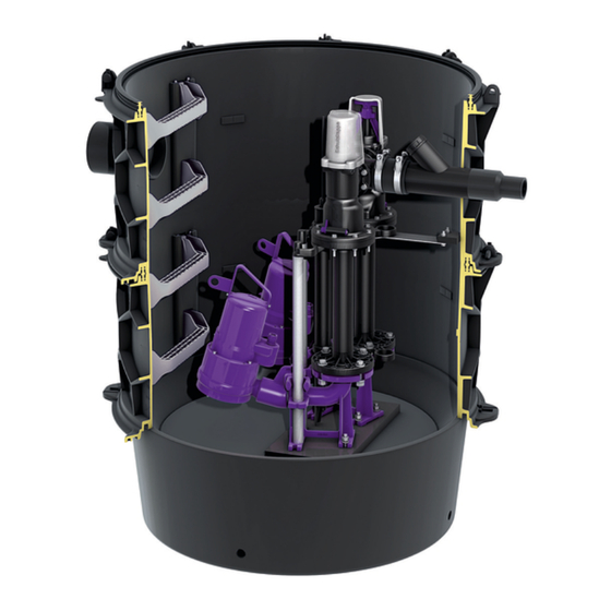
    Anlage mit Gussarmatur Schachtmodul Technikmodul Anbohrfläche für Entlüftungsleitung DN 100 Druckleitungsanschluss DN 80 Spülanschluss 1 1/2“ IG Absperrschieber aus Grauguss Rückflussverhinderer mit Anlüftvorrichtung Fußkrümmer Pumpe (10) Steighilfen (11) Niveauerfassung (Pegelsonde) (12) Zulauf (13) Anbohrfläche für Kabelleerrohr Typenschild Bezeichnung der Anlage Artikelnummer Anschlussspannung und Anschluss- frequenz, Stromaufnahmebereich...
  • Seite 8 Palette 2 Pumpenkralle Niveauerfassung (Pegelsonde) Schaltgerät Dokumente (EBA, Konformitätserklärung...) Pumpen Funktionsprinzip 8 / 124 Pumpstation / Einbau- und Betriebsanleitung 010-992_01...
  • Seite 9: Technische Daten

    Technische Daten Pumpe GTF Grauwasser-Tauchpumpe mit Freistromrad Angabe / Pumpenart 1400 1600 2600 4000 5200 Gewicht 22 kg 27 kg 40 kg 45 kg 56 kg Leistung P1 / P2 1,5 kW / 1,1 kW 1,6 kW / 1,2 kW 2,6 kW / 2,1 kW 4,0 kW / 3,4 kW 5,2 kW / 4,4 kW...
  • Seite 10 Pumpe GTK Grauwasser-Tauchpumpe mit Kanalrad Angabe / Pumpenart 1300 2600 3700 5200 Gewicht 27 kg 40 kg 45 kg 56 kg Leistung P1 / P2 1,3 kW / 1,0 kW 2,6 kW / 2,1 kW 3,7 kW / 3,1 kW 5,2 kW / 4,4 kW Drehzahl 2900 min...
  • Seite 11 Pumpe STZ Schwarzwasser-Tauchpumpe mit Zerhacker Angabe / Pumpenart 1300 2500 3700 Gewicht 27 kg 33 kg 44 kg Leistung P1 / P2 1,3 kW / 0,9 kW 2,5 kW / 1,9 kW 3,7 kW / 3,1 kW Drehzahl 2900 min Betriebsspannung 400 V;...
  • Seite 12: Rohranschlüsse

    Schaltniveaus gelten für Automatikbetrieb S3 Rohranschlüsse Zulauf [DN] Anschluss Druckleitung [DN] 80/50 Kabelleerrohr [DN] Anbohrfläche Entlüftung [DN] Anbohrfläche Spülanschluss 1 1/2“ IG *) maximal DN100 Abmessungen, Volumen Siehe Einbauanleitung KESSEL Technikschacht LW1000 (010-701). 12 / 124 Pumpstation / Einbau- und Betriebsanleitung 010-992_01...
  • Seite 13: Montage

    Montage Allgemeines zur Montage Zur elektrischen Absicherung der Anlage einen FI-Schutzschalter vorsehen. Das Schaltgerät der Anlage so positionieren, dass es zu keiner unbefugten Benutzung kommen kann. Wird die Anlage unbeabsichtigt ausgeschaltet, können Folgeschäden im Gebäude auftreten. Montagereihenfolge Einbau des Technikmoduls. Montage Kabelleerrohr, Entlüftung, Schaltgerät und elektrischer Anschluss.
  • Seite 14: Pumpe Einbringen Und Befestigen

    Pumpe mit Flanschanschluss Sicherstellen, dass Flachdichtung (1) in Pumpenkralle (2) eingelegt ist. Schrauben einschieben und mit Muttern fixieren, jeweils beidseitig Unterlegscheiben einsetzen. Muttern festziehen, bis Pumpenkralle passgenau aufsitzt. Pumpe einbringen und befestigen Kette (1) an Pumpe (2) befestigen. Eine für das Gewicht der Pumpe geeignete Hebehilfe bereitstellen.
  • Seite 15: Niveauerfassung Montieren

    Niveauerfassung montieren Pegelsonde Schutzklappe von Druckmembran abziehen. Sicherstellen, dass der Abstand (L) zwischen Muffenstop- fen (3) und Sondenspitze (4) 630 mm beträgt. Pegelsonde (1) bis zum Anschlag in das Schutzrohr (2) einführen. Variante (A) zeigt die Anlage mit Gussarmatur. Typenschild und Kette befestigen Typenschild im oberen Bereich des Aufsatzstückes innen leicht zugänglich und gut lesbar anbringen.
  • Seite 16: Inbetriebnahme

    Sofern vorhanden, prüfen, ob das Schaltgerät initialisiert wird. ✓ Pumpe läuft selbsttätig an. ✓ Pumpe pumpt bis zum Ausschaltniveau (Pumpenkopf wieder sichtbar) ab. ✓ Pumpe schaltet selbsttätig ab. Schaltgerät auf Fehler/Alarmmeldungen prüfen. Bei Fehler/Alarmmeldungen KESSEL-Kundendienst kontaktieren. 16 / 124 Pumpstation / Einbau- und Betriebsanleitung 010-992_01...
  • Seite 17: Betrieb

    Betrieb Anlage einschalten Alle Rückflussverhinderer müssen während des Betriebs funktionstüchtig sein. Der Absperrschieber muss im Betriebsfall immer geöffnet und mit Sicherungsbügel verriegelt sein. Hauptschalter (1) in Position I (ON) drehen. ✓ Nach erfolgreichem Systemtest erscheinen im Display (2) die Anlageninformationen und die grüne LED (3) leuchtet. ✓...
  • Seite 18 Absperrschieber betätigen Anlage mit Kunststoffarmatur Sicherstellen, dass Absperrschieber im Betriebszustand in offener Position ist! Absperrschieber schließen Schutzkappe abstecken Stützbügel entriegeln Sicherungsbügel 45° nach links drehen Sicherungsbügel nach unten drücken Sicherungsbügel 45° nach rechts drehen ✓ Absperrschieber ist geschlossen und verriegelt Absperrschieber öffnen In umgekehrter Reihenfolge verfahren, wie vorhergehend beschrieben.
  • Seite 19: Wartung

    Pumpe (1) an der Kette (2) langsam nach oben aus dem Schacht herausziehen. VORSICHT Angestautes Abwasser läuft aus! Pumpenteile auf Verformung und Ablagerungen prüfen, ggf. KESSEL-Service kontaktieren. Leichtgängigkeit der beweglichen Teile sicherstellen. Sichtprüfung der Armaturenkomponenten durchführen. Sicherstellen, dass die Ansaugöffnung der Pumpe frei von Schweb- und Feststoffen ist, ggf. reinigen.
  • Seite 20 Anlagenbehälter reinigen Anlagenbehälter (Schacht) entleeren. Das kann mit einem Nasssauger durchgeführt werden. Sicherstellen, dass der Anlagenbehälter (Schacht) frei von Schweb- und Feststoffen ist, ggf. reinigen. Sicherstellen, dass das Schutzrohr der Niveauerfas- sung (1) frei von Schweb- und Feststoffen ist, ggf. reini- gen.
  • Seite 21 Rückflussverhinderer Kunststoffarmatur Anlüftvorrichtung (5) am Rückflussverhinderer (2) in waagerechte Position bringen. Das zurückgestaute Abwasser kann von der Druckleitung in den Anlagenbehälter zurücklaufen. Rückflussverhinderer (2) ausbauen und reinigen Schrauben (1) und (3) herausschrauben, Rückflussverhinderer (2) seitlich herausschieben und reinigen. Klappensicherung (4) entfernen. Rückschlagklappe abziehen, auf Verschleiß...
  • Seite 22 Pumping station / Installation and operating manual Dear customer, As a premium manufacturer of innovative products for draining technology, KESSEL offers integrated system solutions and customer-oriented service. In doing so, we set the highest quality standards and focus firmly on sustainability - not only with the manufacturing of our products, but also with regard to their long-term operation and we strive to ensure that you and your property are protected over the long term.
  • Seite 23: Notes On This Manual

    Notes on this manual The following conventions help navigating the manual: Symbol Explanation See Figure 1 Position number 5 from the adjacent figure Action step in figure Check whether manual control Prerequisite for action has been acti- vated. Press OK. Action step ✓...
  • Seite 24: Safety

    Safety General safety notes The manuals for the system and parts thereof as well as the maintenance records and handover certificates must be kept available near the system. The accident prevention regulations, the applicable standards and directives as well as the regulations from the local energy and supply companies must be observed during the installation, operation, maintenance and repair of the system.
  • Seite 25: Intended Use

    Variants The systems of the XL series for wet installation are available in the variants Aqualift F XL and Aqualift S XL. The Mono and Duo variants are equipped with one or two pumps respectively. The layout and piping of the two variants is designed sym- metrically in order to make later conversion possible (Mono to Duo and vice versa).
  • Seite 26 Design The system comprises the technical module (1) and cham- ber module (2). The technical module holds the pump(s) and the level mea- surement. Different chamber elements (intermediate sec- tions, taper etc.) can be mounted on the technical module. Technical module and chamber module together form the system.
  • Seite 27: Type Plate

    System with fittings made of grey cast iron Chamber module Technical module Pre-scored area for ventilation pipe DN 100 Pressure pipe connection DN 80 Flushing connection 1 1/2" inner thread Shut-off valve made of grey cast iron Backflow preventer with ventilation device Base elbow Pump (10)
  • Seite 28: How It Works

    Pallet 2 Pump clamp Level measurement (level sensor) Control unit Documents (installation instruc- tions, Declaration of Conformity, ...) Pumps How it works 28 / 124 Pumping station / Installation and operating manual 010-992_01...
  • Seite 29: Technical Data

    Technical data GTF pump Submersible grey water pump with multi-vane impeller Information / pump type 1400 1600 2600 4000 5200 Weight 22 kg 27 kg 40 kg 45 kg 56 kg Power P1 / P2 1.5 kW / 1.1 kW 1.6 kW / 1.2 kW 2.6 kW / 2.1 kW 4.0 kW / 3.4 kW...
  • Seite 30 GTK pump Submersible grey water pump with channel impeller Information / pump type 1300 2600 3700 5200 Weight 27 kg 40 kg 45 kg 56 kg Power P1 / P2 1.3 kW / 1.0 kW 2.6 kW / 2.1 kW 3.7 kW / 3.1 kW 5.2 kW / 4.4 kW Speed...
  • Seite 31 STZ pump Submersible black water pump with macerating system Information / pump type 1300 2500 3700 Weight 27 kg 33 kg 44 kg Power P1 / P2 1.3 kW / 0.9 kW 2.5 kW / 1.9 kW 3.7 kW / 3.1 kW Speed 2900 rpm Operating voltage...
  • Seite 32: Pipe Connections

    Cable conduit [DN] Pre-scored area Ventilation [DN] Pre-scored area Flushing connection 1 1/2" inner thread *) maximum DN100 Dimensions, volume See installation instructions for KESSEL engineering cham- ber LW1000 (010-701). 32 / 124 Pumping station / Installation and operating manual 010-992_01...
  • Seite 33: Installation

    Installation General installation information A residual current circuit breaker must be provided as electrical protection for the system. The system's control unit must be positioned in such a way as to prevent any unauthorised use. Consequential damage can occur in the building if the system is switched off accidentally. Assembly sequence Installation of the technical module.
  • Seite 34: Positioning The Pump And Fixing It In Place

    Pump with flange connection Make sure that the flat seal (1) has been placed in the pump clamp (2). Insert screws and fix with nuts, using washers on both sides. Tighten nuts until the pump clamp fits perfectly. Positioning the pump and fixing it in place Fix the chain (1) to the pump (2).
  • Seite 35: Fixing Type Plate And Chain In Place

    Installing level measurement Level sensor Remove the protective flap from the pressure diaphragm. Make sure that the distance (L) between the blind plug (3) and the sensor tip (4) is 630 mm. Insert the level sensor (1) into the protective tube (2) as far as it will go.
  • Seite 36: Commissioning

    ✓ The pump pumps out water until the switch-off level is reached (pump head visible again). ✓ Pump switches off automatically. Check the control unit for errors/alarm signals. In the event of errors/alarm signals, contact KESSEL Customer Services. 36 / 124...
  • Seite 37: Operation

    Operation Switching on the system All backflow preventers must be functional during operation. During operation, the shut-off valve must always be open and locked with a valve lock. Turn main switch (1) to I (ON) position. ✓ Following a successful system test, the system informa- tion appears on the display (2) and the green LED (3) lights up.
  • Seite 38 Actuating the shut-off valve System with polymer fitting Make sure that the shut-off valve is in the open position in operating state! Close the shut-off valve Remove the protective cap Release the supporting yoke Turn the circlip 45° anti-clockwise Press the circlip downwards Turn the circlip 45°...
  • Seite 39: Maintenance

    CAUTION Accumulated wastewater flows out! Check the pump parts for deformation and deposits, con- tact KESSEL service department if necessary. Ensure the moving parts can move easily. Carry out a visual check of the fitting components. Make sure that the pump intake is free of suspended mat- ter and solids, clean if necessary.
  • Seite 40: Level Sensor

    Cleaning the system tank Drain the system tank (chamber). This can be done using a wet vacuum cleaner. Make sure that the system tank (chamber) is free of sus- pended matter and solids, clean if necessary. Make sure that the protective tube for level measure- ment (1) is free of suspended matter and solids, clean if necessary.
  • Seite 41: Backflow Preventer

    Backflow preventer Polymer fitting Move the ventilation device (5) on the backflow preventer (2) to a horizontal position. The accumulated wastewater can flow back from the pressure pipe into the system tank. Remove and clean the backflow preventer (2) Undo screws (1) and (3), push out the backflow preventer(2) from the side and clean it. Remove the flap catch (4).
  • Seite 42 Poste de relevage / Instructions de pose et d’utilisation Chère cliente, cher client, En qualité de producteur de pointe de produits novateurs dans le domaine de la technique d’assainissement, KESSEL pro- pose des réponses systématiques globales et un service orienté aux besoins de la clientèle. Nous misons simultanément sur les normes de qualité...
  • Seite 43: Informations Spécifiques Aux Présentes Instructions

    Informations spécifiques aux présentes instructions Les conventions de représentation suivantes facilitent l’orientation : Représentation Explication voir figure 1 Numéro de repère 5 de la figure ci-contre Action de la figure Vérifier si la commande manuelle a été acti- Condition de réalisation de l’action vée.
  • Seite 44: Sécurité

    Sécurité Consignes de sécurité générales Les instructions spécifiques au système et aux composants du système ainsi que les procès-verbaux de maintenance et de réception doivent toujours se situer à proximité du système. L'installation, l'utilisation, la maintenance ou la réparation du système pose toujours pour condition de respecter les direc- tives de prévention des accidents, ainsi que les normes, directives et prescriptions des entreprises d'approvisionnement en énergie sur le plan local s’y rapportant.
  • Seite 45: Personnel Qualification

    Variantes Les postes de la série XL pour pose immergée sont disponibles dans les variantes Aqualift F XL et Aqualift S XL Les variantes Mono et Duo sont synonymes d'un équipement avec une ou deux pompes. La structure des deux variantes et leur tubulure sont symétriques pour faciliter le rééquipement (de Mono à...
  • Seite 46 Structure Le poste est composé d'un module pompe (1) et d’un module rehausse (2). La/les pompes et la détection du niveau sont logées dans le module pompe. Le module pompe se prête au montage de différents éléments de rehausse, cône etc). La combinaison du module pompe et module rehausse forme le poste.
  • Seite 47: Plaque Signalétique

    Poste avec dispositif d'arrêt en fonte grise Module rehausse Module pompe Surface de perçage pour la conduite d'aération et de ventilation DN 100 Conduite de refoulement DN 80 Raccord de rinçage 1 1/2“ IG Dispositif d'arrêt en fonte grise Dispositif antiretour avec dispositif de purge d’air Coude inférieur Pompe (10)
  • Seite 48: Principe De Fonctionnement

    Palette 2 Griffe de pompe Détection du niveau (sonde de niveau) Gestionnaire Documents (instructions de pose et d'uti- lisation, déclaration de conformité...) Pompes Principe de fonctionnement 48 / 124 Poste de relevage / Instructions de pose et d’utilisation 010-992_01...
  • Seite 49: Caractéristiques Techniques

    Caractéristiques techniques Pompe GTF Pompe submersible pour eaux usées domestiques avec roue vortex Indication / type de pompe 1400 1600 2600 4000 5200 Poids 22 kg 27 kg 40 kg 45 kg 56 kg Puissance P1 / P2 1,5 kW / 1,1 kW 1,6 kW / 1,2 kW 2,6 kW / 2,1 kW 4,0 kW / 3,4 kW...
  • Seite 50 Pompe GTK Pompe submersible pour eaux usées domestiques avec roue à canal Indication / type de pompe 1300 2600 3700 5200 Poids 27 kg 40 kg 45 kg 56 kg Puissance P1 / P2 1,3 kW / 1,0 kW 2,6 kW / 2,1 kW 3,7 kW / 3,1 kW 5,2 kW / 4,4 kW Régime...
  • Seite 51 Pompe STZ Pompe submersible pour eaux vannes avec hachoir Indication / type de pompe 1300 2500 3700 Poids 27 kg 33 kg 44 kg Puissance P1 / P2 1,3 kW / 0,9 kW 2,5 kW / 1,9 kW 3,7 kW / 3,1 kW Régime 2900 tr/min Tension de service...
  • Seite 52: Volumes Utiles / Niveau De Commutation

    Ventilation [DN] Surface de perçage Raccord de rinçage 1 1/2“ IG Titre *) maximum DN100 Dimensions, volume Voir les instructions de pose du module rehausse KESSEL LW1000 (010-701) 52 / 124 Poste de relevage / Instructions de pose et d’utilisation 010-992_01...
  • Seite 53: Montage

    Montage Conseils de montage d'ordre général Prévoir un interrupteur de protection contre les courants de surcharge électrique du poste. Positionner le gestionnaire du poste de sorte à exclure toute utilisation non autorisée. La mise hors circuit par inadvertance du poste risque de causer des dommages consécutifs ou indirects au bâtiment. Ordre de montage Mise en place du module pompe.
  • Seite 54 Pompe avec raccord à bordure S'assurer que le joint plat (1) est inséré dans la griffe de pompe (2). Introduire les vis et les fixer avec des écrous, insérer des rondelles sur les deux faces. Serrer les écrous jusqu’à ce que la griffe de pompe soit parfaitement ajustée.
  • Seite 55: Montage Du Gestionnaire

    Montage de la détection du niveau Sonde de niveau Retirer le clapet de protection de la membrane de pres- sion. S’assurer que l’écart (L) entre le bouchon de man- chon (3) et la pointe de la sonde (4) soit de 630 mm. Engager la sonde de niveau (1) jusqu’à...
  • Seite 56: Mise En Service

    ✓ La pompe refoule l’eau jusqu’au niveau d’arrêt (la tête de pompe est à nouveau visible). ✓ La pompe se déconnecte automatiquement. Vérifier l’absence de messages d’erreur ou d'alarme du gestionnaire. Contacter le service après-vente KESSEL en cas de messages d’erreur ou d'alarme.
  • Seite 57: Fonctionnement

    Fonctionnement Activation du poste Tous les dispositifs antiretour doivent demeurer aptes au fonctionnement pendant le service. En service, le dispositif d’arrêt doit toujours rester ouvert et verrouillé à l'aide de l’étrier de sécurité. Tourner l’interrupteur principal (1) à la position I (ON). ✓...
  • Seite 58 Actionnement du dispositif d’arrêt Poste avec dispositif d'arrêt en composite S'assurer que le dispositif d’arrêt est en position ouverte tant qu’il est en fonctionnement ! Fermeture du dispositif d’arrêt Retirer le capuchon de protection Déverrouiller la bride de soutien Tourner l’étrier de sécurité de 45° vers la gauche Presser l’étrier de sécurité...
  • Seite 59: Maintenance

    Les eaux usées accumulées s’échappent ! Vérifier si les pièces de la pompe présentent des défor- mations et des dépôts. Au besoin, contacter le service KESSEL. S’assurer que les pièces mobiles se déplacent sans entrave. Procéder à un contrôle visuel des composants de la canalisation de refoulement.
  • Seite 60 Nettoyage de la cuve Vider la cuve (regard). Se servir par exemple d'un aspira- teur à eau. S'assurer de l'absence de substances en suspension et de matières solides dans la cuve (regard), nettoyer si nécessaire. S'assurer de l'absence de substances en suspension et de matières solides dans le tube de protection de la détection du niveau (1), nettoyer si nécessaire.
  • Seite 61 Dispositif antiretour Poste avec dispositif d'arrêt et canalisation de refoulement en composite Amener le dispositif de purge d’air (5) sur le dispositif antiretour (2) en position horizontale. Les eaux usées accumulées peuvent refluer dans la cuve par la conduite de refoulement. Démonter le dispositif antiretour (2) et le nettoyer Dévisser les vis (1) et (3) et glisser le dispositif antiretour (2) latéralement vers l'extérieur et le nettoyer Retirer la sécurité...
  • Seite 62 Cara cliente, caro cliente, in qualità di produttore premium di prodotti innovativi per la tecnica di drenaggio, KESSEL offre soluzioni di sistema integrate e un servizio orientato al cliente. Puntiamo sui massimi standard qualitativi e ci impegniamo coerentemente per la sosteni- bilità...
  • Seite 63: Indicazioni Sulle Presenti Istruzioni

    Indicazioni sulle presenti istruzioni Le seguenti convenzioni illustrative semplificano l’orientamento: Simbolo Spiegazione vedere figura 1 Posizione numero 5 della figura accanto Passaggio procedurale nella figura Controllare se il comando manuale è stato Presupporti per l’azione attivato. Premere OK. Passaggio procedurale ✓...
  • Seite 64: Sicurezza

    Sicurezza Avvertenze di sicurezza generali Le istruzioni dell’impianto e i componenti dell’impianto, al pari del verbale di consegna e manutenzione, devono essere man- tenuti disponibili presso l’impianto. Durante l’installazione, il funzionamento, la manutenzione o la riparazione dell’impianto devono essere rispettate le norme antinfortunistiche, le norme e le direttive pertinenti e le prescrizioni delle aziende di energia e fornitura locali.
  • Seite 65: Uso Conforme Alla Destinazione

    (pompa, rilevazione del livello e centralina), soddisfa i requisiti ATEX. Il modello Aqualift S XL è dotato di pompe ad immersione per le acque grigie realizzate con girante libera o girante a canale (GTF o GTK). Queste sono pensate per le acque di scarico non contenenti sostanze fecali.
  • Seite 66 Struttura L’impianto è composto dal modulo tecnico (1) e dal modulo del pozzetto (2). Il modulo tecnico accoglie la pompa (o le pompe) e la rileva- zione del livello. Sul modulo tecnico possono essere montati diversi elementi del pozzetto. Modulo tecnico e modulo del pozzetto assieme formano l’impianto.
  • Seite 67 Impianto con paletta di chiusura in ghisa grigia Modulo del pozzetto Modulo tecnico Superficie perforabile per il con- dotto di aerazione e sfiato DN 100 Collegamento del condotto di mandata DN 80 Collegamento di spurgo 1 1/2” IG Paletta di chiusura in ghisa grigia Blocco antiriflusso con dispositivo di sfiato Piedi di accoppiamento Pompa...
  • Seite 68: Principio Di Funzionamento

    Pallet 2 Artiglio della pompa Rilevazione del livello (sonda di livello) Centralina Documenti (istruzioni per l’installazione e l’uso, dichiarazione di conformità, ecc.) Pompe Principio di funzionamento 68 / 124 Stazione di pompaggio / Istruzioni per l’installazione e l’uso 010-992_01...
  • Seite 69: Dati Tecnici

    Dati tecnici Pompa GTF Pompa ad immersione per acque grigie con girante libera Indicazione / tipo di pompa 1400 1600 2600 4000 5200 Peso 22 kg 27 kg 40 kg 45 kg 56 kg Potenza P1 / P2 1,5 kW / 1,1 kW 1,6 kW / 1,2 kW 2,6 kW / 2,1 kW 4,0 kW / 3,4 kW...
  • Seite 70 Pompa GTK Pompa ad immersione per acque grigie con girante a canale Indicazione / tipo di pompa 1300 2600 3700 5200 Peso 27 kg 40 kg 45 kg 56 kg Potenza P1 / P2 1,3 kW / 1,0 kW 2,6 kW / 2,1 kW 3,7 kW / 3,1 kW 5,2 kW / 4,4 kW Numero di giri...
  • Seite 71 Pompa STZ Pompa ad immersione per acque nere con trituratore Indicazione / tipo di pompa 1300 2500 3700 Peso 27 kg 33 kg 44 kg Potenza P1 / P2 1,3 kW / 0,9 kW 2,5 kW / 1,9 kW 3,7 kW / 3,1 kW Numero di giri 2.900 min Tensione di funzionamento...
  • Seite 72 Sfiato [DN] Superficie perforabile Collegamento di spurgo 1 1/2” IG Titolo *) max DN100 Misure, volumi Vedere le istruzioni di installazione del pozzetto tecnico KESSEL LW1000 (010-701). 72 / 124 Stazione di pompaggio / Istruzioni per l’installazione e l’uso 010-992_01...
  • Seite 73: Montaggio

    Montaggio Informazioni generali sul montaggio Per la sicurezza elettrica dell’impianto deve essere previsto un interruttore differenziale. Posizionare la centralina dell’impianto in modo che non possa avvenire alcun uso non autorizzato. Se l’impianto viene spento inavvertitamente possono verificarsi dei danni conseguenti nell’edificio. Sequenza di montaggio Installazione del modulo tecnico.
  • Seite 74 Pompa con attacco a flangia Accertare che la guarnizione piatta (1) sia posta nell’arti- glio della pompa (2). Inserire le viti e fissare con i dadi, impiegando rispettiva- mente una rondella su entrambi i lati. Serrare i dadi fino a che l’artiglio della pompa non poggia con la massima precisione.
  • Seite 75: Montaggio Della Centralina

    Montaggio della rilevazione del livello Sonda di livello Togliere il tappo protettivo dalla membrana di pressuriz- zazione. Accertare che la distanza (L) tra tappo di chiusura (3) e punta della sonda (4) sia pari a 630 mm. Inserire la sonda di livello (1) nel tubo protettivo (2) fino all’arresto.
  • Seite 76: Messa In Funzione

    ✓ La pompa effettua il pompaggio fino al livello di spegnimento (testa della pompa nuovamente visibile). ✓ La pompa si spegne autonomamente. Controllare la presenza di errori/segnalazioni di allarme sulla centralina. Contattare il servizio clienti KESSEL in presenza di errori/segnalazioni di allarme.
  • Seite 77: Funzionamento

    Funzionamento Accensione dell’impianto Tutti i blocchi antiriflusso devono essere funzionanti durante il funzionamento. In caso di funzionamento, la paletta di chiusura deve essere sempre aperta e serrata con la staffa di sicurezza. Ruotare l’interruttore principale (1) in posizione I (ON). ✓...
  • Seite 78 Azionamento della paletta di chiusura Impianto con valvola in materiale plastico Accertare che la paletta di chiusura sia in posizione aperta in condizione di funzionamento! Chiusura della paletta di chiusura Togliere il cappuccio di protezione Sbloccare la staffa di supporto Ruotare la staffa di sicurezza di 45°...
  • Seite 79: Manutenzione

    Fuoriuscita delle acque di scarico accumulatesi! Controllare la presenza di deformazioni e depositi sulle parti della pompa, eventualmente contattare il servizio KESSEL. Accertare la mobilità della parti mobili. Eseguire un controllo visivo dei componenti delle valvole. Accertare che l’apertura di aspirazione della pompa sia priva di sostanze in sospensione e solide, eventualmente lavarla.
  • Seite 80 Pulizia del serbatoio Svuotare il serbatoio (pozzetto). Questa operazione può avvenire con un aspiraliquidi. Accertare che il serbatoio (pozzetto) sia privo di sostanze in sospensione e solide, eventualmente lavarlo. Accertare che il tubo protettivo della rilevazione del livello (1) sia privo di sostanze in sospensione e solide, even- tualmente lavarlo.
  • Seite 81 Blocco antiriflusso Impianto con valvola e tubazione di mandata in materiale plastico Portare il dispositivo di sfiato (5) sul blocco antiriflusso (2) in posizione orizzontale. Le acque di scarico stagnanti possono rifluire nel serbatoio dal condotto di mandata. Smontaggio e pulizia del blocco antiriflusso (2) Svitare le viti (1) e (3), spingere fuori lateralmente il blocco antiriflusso (2) e pulirlo.
  • Seite 82 Pompstation / Inbouw- en bedieningshandleiding Beste klant, Als premium fabrikant van innovatieve producten voor de afwateringstechniek biedt KESSEL totale systeemoplossingen en klantgerichte service. Wij stellen hierbij maximale kwaliteitsnormen en zetten consequent in op duurzaamheid, niet alleen bij de productie van onze producten, maar ook met het oog op hun langdurige gebruik zetten wij ons in voor een permanente bescherming van u en uw eigendom.
  • Seite 83: Informatie Over Deze Handleiding

    Informatie over deze handleiding De volgende weergaveconventies maken de oriëntatie eenvoudiger: Afbeelding Uitleg zie afbeelding 1 Positienummer 5 van nevenstaande afbeelding Handeling op de afbeelding … Controleren of de handbesturing is inge- Voorwaarde voor de handeling schakeld. Op OK drukken. Werkstap ✓...
  • Seite 84: Veiligheid

    Veiligheid Algemene veiligheidsinstructies De handleidingen van de installatie en installatieonderdelen alsmede de onderhouds- en overdrachtsprotocollen moeten bij de installatie beschikbaar worden gehouden. Bij de installatie, het gebruik, het onderhoud of de reparatie van de installatie moeten de ongevalpreventievoorschriften, de in aanmerking komende normen en richtlijnen alsmede de voorschriften van de plaatselijke nutsbedrijven in acht worden genomen.
  • Seite 85: Reglementair Gebruik

    Varianten De installaties uit de constructieserie XL voor natte opstelling zijn verkrijgbaar in de varianten Aqualift F XL en Aqualift S XL. De varianten Mono en Duo komen overeen met de uitrusting met een of twee pompen. De opbouw en het leidingwerk van beide varianten zijn symmetrisch ontworpen om ombouw naderhand (Mono naar Duo en omgekeerd) mogelijk te maken.
  • Seite 86 Opbouw De installatie bestaat uit een techniekmodule (1) en een schachtmodule (2). In de techniekmodule bevinden zich de pomp(en) en de niveaudetectie. Op de techniekmodule kunnen verschillende schachtelementen worden gemonteerd. Techniekmodule en schachtmodule vormen samen het pompstation. Installatie met afsluiter van kunststof Schachtmodule Techniekmodule Boorvlak voor de be- en ontluchtingsleiding DN 100...
  • Seite 87 Installatie met afsluiter van gietijzer Schachtmodule Techniekmodule Boorvlak voor de be- en ontluchtingsleiding DN 100 Persleiding DN 80 Spoelaansluiting 1 1/2″ IG Afsluiter van gietijzer Terugslagklep met ontluchtingsvoorziening Voetbocht Pomp (10) Klimhulp (11) Niveaudetectie (peilsonde) (12) Toevoer (13) Boorvlak voor mantelbuis Typeplaatje Aanduiding van de installatie Artikelnummer...
  • Seite 88 Pallet 2 Pompklauw Niveaudetectie (peilsonde) Besturingskast Documenten (inbouw- en bedieningshand- leiding, verklaring van overeenstemming ...) Pompen Werkingsprincipe 88 / 124 Pompstation / Inbouw- en bedieningshandleiding 010-992_01...
  • Seite 89: Technische Gegevens

    Technische gegevens Pomp GTF Dompelpomp met open waaier voor grijswater Informatie / soort pomp 1400 1600 2600 4000 5200 Gewicht 22 kg 27 kg 40 kg 45 kg 56 kg Vermogen P1 / P2 1,5 kW / 1,1 kW 1,6 kW / 1,2 kW 2,6 kW / 2,1 kW 4,0 kW / 3,4 kW 5,2 kW / 4,4 kW...
  • Seite 90 Pomp GTK Dompelpomp met kanaalwaaier voor grijswater Informatie / soort pomp 1300 2600 3700 5200 Gewicht 27 kg 40 kg 45 kg 56 kg Vermogen P1 / P2 1,3 kW / 1,0 kW 2,6 kW / 2,1 kW 3,7 kW / 3,1 kW 5,2 kW / 4,4 kW Toerental 2900 min...
  • Seite 91 Pomp STZ Dompelpomp met snijwerk voor zwart water Informatie / soort pomp 1300 2500 3700 Gewicht 27 kg 33 kg 44 kg Vermogen P1 / P2 1,3 kW / 0,9 kW 2,5 kW / 1,9 kW 3,7 kW / 3,1 kW Toerental 2900 min Bedrijfsspanning...
  • Seite 92: Nuttige Volumes/Schakelniveau

    Leidingen aansluiten Toevoer [DN] Aansluiting persleiding [DN] 80/50 Mantelbuis [DN] Boorvlak Be- en ontluchting [DN] Boorvlak Spoelaansluiting 1 1/2″ IG Titel *) maximaal DN100 Afmetingen, volume Zie de inbouwhandleiding KESSEL-techniekschacht LW1000 (010-701). 92 / 124 Pompstation / Inbouw- en bedieningshandleiding 010-992_01...
  • Seite 93: Montage

    Montage Algemene montage-informatie De installatie moet met een aardlekschakelaar elektrisch worden beveiligd. De besturingskast van die installatie moet zodanig zijn gepositioneerd, dat gebruik door onbevoegden onmogelijk is. Als de installatie per ongeluk wordt uitgeschakeld, kan dat tot schade in het gebouw leiden. Montagevolgorde Inbouw van de techniekmodule.
  • Seite 94 Pomp met flensaansluiting Zorgen dat de pakking (1) in de pompklauw (2) is geplaatst. Bouten indraaien en met moeren vastzetten, aan beide kanten ringen aanbrengen. Moeren aandraaien tot de pompklauw perfect past. Pomp plaatsen en bevestigen Ketting (1) aan de pomp (2) bevestigen. Een voor het gewicht van de pomp geschikt hijsmiddel beschikbaar stellen.
  • Seite 95 Niveaudetectie monteren Peilsonde Beschermkap van het drukmembraam verwijderen. Zorgen dat de afstand (L) tussen de mofafdekking (3) en punt van de sonde (4) 630 mm bedraagt. Peilsonde (1) tot aan de aanslag in de beschermingsbuis (2) steken. Variant (A) toont de installatie met gegoten armatuur. Typeplaatje en ketting bevestigen Typeplaatje bovenaan het opzetstuk gemakkelijk toegan- kelijk en goed leesbaar aanbrengen.
  • Seite 96: Inbedrijfstelling

    ✓ De pomp pompt tot het uitschakelniveau is bereikt (de pompkop wordt weer zichtbaar). ✓ De pomp gaat automatisch uit. Besturingskast op storingen/alarmmeldingen controleren. Bij storingen/alarmmeldingen contact opnemen met de KESSEL-klantenservice. 96 / 124 Pompstation / Inbouw- en bedieningshandleiding 010-992_01...
  • Seite 97: Gebruik

    Gebruik De installatie inschakelen Alle terugslagkleppen moeten tijdens het bedrijf correct functioneren. De afsluiter moet tijdens bedrijf altijd zijn geopend en met een beschermingsbeugel zijn vergrendeld. Hoofdschakelaar (1) in stand I (ON ) zetten. ✓ Na een succesvolle systeemtest verschijnt op het scherm (2) de informatie over de installatie en gaat de groene led (3) branden.
  • Seite 98 Afsluiter gebruiken Installatie met kunststofarmatuur Zorgen dat de afsluiter in bedrijfstoestand openstaat! Afsluiter sluiten Beschermkap losmaken Beschermingsbeugel ontgrendelen Beschermingsbeugel 45° naar links draaien Beschermingsbeugel omlaagdrukken Beschermingsbeugel 45° naar rechts draaien ✓ De afsluiter is gesloten en vergrendeld Afsluiter openen In omgekeerde volgorde te werk gaan als boven staat beschreven.
  • Seite 99: Onderhoud

    Waterkolom loopt terug! Onderdelen van de pomp controleren op vervormin- gen en sediment, eventueel contact opnemen met de KESSEL-klantenservice. Controleren of de beweegbare delen makkelijk bewegen. Onderdelen van de armaturen visueel controleren. Waarborgen dat de aanzuigopening van de pomp geen zwevende en vaste stoffen bevat, eventueel reinigen.
  • Seite 100 Het reservoir reinigen Het reservoir (schacht) leegmaken. Voor het legen kan een natzuiger worden gebruikt. Waarborgen dat het reservoir (schacht) geen zwevende en vaste stoffen bevat, eventueel reinigen. Waarborgen dat de beschermingsbuis van de niveaude- tectie (1) vrij van zwevende en vaste stoffen is, eventueel reinigen.
  • Seite 101 Terugslagklep Kunststofarmatuur Ontluchtingsvoorziening (5) bij de terugslagklep (2) in horizontale positie brengen. Het teruggestuwde afvalwater kan van de persleiding in het reservoir teruglopen. Terugslagklep (2) demonteren en reinigen. Schroeven (1) en (3) losschroeven, terugslagklep (2) horizontaal verwijderen en reinigen. Kleppenbescherming (4) verwijderen. Terugslagklep verwijderen, op slijtage controleren, eventueel blokkerende onderdelen verwijderen en doorspoelen.
  • Seite 102 Przepompownia / Instrukcja zabudowy i obsługi Szanowna Klientko, szanowny Kliencie! Jako producent najwyższej klasy innowacyjnych produktów z zakresu techniki odwadniania firma KESSEL oferuje komplek- sowe rozwiązania systemowe i serwis odpowiadający potrzebom klientów. Konsekwentnie stawiamy na jakość i trwałość rozwiązań. Nie tylko podczas produkcji naszych urządzeń, lecz również w zakresie ich długotrwałego użytkowania dbamy o to, by zagwarantowane było bezpieczeństwo użytkownika i jego mienia.
  • Seite 103: Wskazówki Dotyczące Niniejszej Instrukcji

    Wskazówki dotyczące niniejszej instrukcji Poniższe formy oznaczeń ułatwiają orientację: Oznaczenie Objaśnienie patrz rys. 1 Numer pozycji 5 na rysunku obok Krok postępowania na rysunku Sprawdzić, czy aktywowane zostało stero- Warunek postępowania wanie ręczne. Nacisnąć przycisk OK. Krok postępowania ✓ Urządzenie jest gotowe do pracy. Wynik postępowania Odniesienie do rozdz.
  • Seite 104: Bezpieczeństwo

    Bezpieczeństwo Ogólne zasady bezpieczeństwa Instrukcje montażu urządzenia oraz jego poszczególnych części jak również protokoły konserwacji i przekazania należy przechowywać w pobliżu urządzenia. Podczas instalacji, obsługi, konserwacji lub naprawy urządzenia należy przestrzegać przepisów dotyczących zapobiega- nia wypadkom, odpowiednich norm i dyrektyw oraz przepisów miejscowych przedsiębiorstw energetycznych i dostawców mediów.
  • Seite 105: Zastosowanie Zgodnie Z Przeznaczeniem

    Opis wyrobu Wersje Urządzenia z serii XL do ustawienia mokrego są dostępne w wariantach Aqualift F XL i Aqualift S XL. Warianty Mono i Duo posiadają odpowiednio jedną lub dwie pompy. Konstrukcja i orurowanie w obydwóch wariantach są wykonane w sposób symetryczny, przez co możliwe jest późniejsze przezbrojenie urządzenia (z Mono na Duo i na odwrót).
  • Seite 106 Budowa Urządzenie składa się z modułu technicznego (1) i modułu studzienki (2). W module technicznym znajdują się pompa/pompy i urzą- dzenie do rozpoznawania poziomu. Na module technicznym można montować różne komponenty studzienki. Modułu technicznego i modułu studzienki tworzą razem urządzenie. Urządzenie z zasuwą...
  • Seite 107: Tabliczka Znamionowa

    Urządzenie z zasuwą odcinającą z żeliwa szarego Moduł studzienki Moduł techniczny Miejsce na otwór na przewód wentylacyjny DN 100 Przyłącze przewodu tłocznego DN 80 Przyłącze płukania 1 1/2“ IG Zasuwa odcinająca z żeliwa szarego Zawór zwrotny z napowietrzaczem Kolano kołnierzowe ze stopką Pompa (10) Stopnie złazowe...
  • Seite 108: Zasada Działania

    Paleta 2 Pazur pompy Urządzenie do rozpoznawania poziomu (sonda hydrostatyczna) Urządzenie sterujące Dokumenty (instrukcja zabudowy i obsługi, deklaracja zgodności...) Pompy Zasada działania 108 / 124 Przepompownia / Instrukcja zabudowy i obsługi 010-992_01...
  • Seite 109: Dane Techniczne

    Dane techniczne Pompa GTF Pompa zanurzeniowa do wody szarej z wirnikiem z wolnym przelotem Dane / typ pompy 1400 1600 2600 4000 5200 Ciężar 22 kg 27 kg 40 kg 45 kg 56 kg Pobór mocy P1 / P2 1,5 kW / 1,1 kW 1,6 kW / 1,2 kW 2,6 kW / 2,1 kW 4,0 kW / 3,4 kW...
  • Seite 110 Pompa GTK Pompa zanurzeniowa do wody szarej z wirnikiem kanałowym Dane / typ pompy 1300 2600 3700 5200 Ciężar 27 kg 40 kg 45 kg 56 kg Pobór mocy P1 / P2 1,3 kW / 1,0 kW 2,6 kW / 2,1 kW 3,7 kW / 3,1 kW 5,2 kW / 4,4 kW Prędkość...
  • Seite 111 Pompa STZ Pompa zanurzeniowa do wody czarnej z rozdrabniaczem Dane / typ pompy 1300 2500 3700 Ciężar 27 kg 33 kg 44 kg Pobór mocy P1 / P2 1,3 kW / 0,9 kW 2,5 kW / 1,9 kW 3,7 kW / 3,1 kW Prędkość...
  • Seite 112: Objętości Użytkowe / Poziom Przełączania

    Rura ochronna na kable [DN] Miejsce na otwory Odpowietrzanie [DN] Miejsce na otwory Przyłącze płukania 1 1/2“ IG *) maks. DN100 Wymiary, pojemność Patrz instrukcja montażu studzienki technicznej firmy KESSEL LW1000 (010-701). 112 / 124 Przepompownia / Instrukcja zabudowy i obsługi 010-992_01...
  • Seite 113: Montaż

    Montaż Informacje ogólne na temat montażu Urządzenie należy wyposażyć w zabezpieczający elektrycznie bezpiecznik różnicowo-prądowy. Urządzenie sterujące należy ustawić w takim miejscu, aby nie mogło dojść do jego nieupoważnionego użycia. W przypadku niezamierzonego wyłączenia urządzenia może dojść do szkód następczych w budynku. Kolejność...
  • Seite 114 Pompa z przyłączem kołnierzowym Upewnić się, że w pazur pompy (2) włożona jest uszczelka płaska (1). Wsunąć śruby i ustalić nakrętkami, włożyć z obu stron podkładki. Dociągnąć nakrętki aż pazur pompy będzie dokładnie przylegał. Włożenie i przymocowanie pompy Przymocować łańcuch (1) do pompy (2). Przygotować...
  • Seite 115: Montaż Urządzenia Sterującego

    Montaż urządzenia do rozpoznawania poziomu Sonda hydrostatyczna Zdjąć osłonę z membrany. Upewnić się, że odstęp (L) między zatyczką kielichową (3) i końcówką sondy (4) wynosi 630 mm. Włożyć sondę hydrostatyczną (1) do oporu w rurę ochronną (2). Wariant (A) to urządzenie z zasuwą odcinającą z żeliwa. Przymocowanie tabliczki znamionowej i łańcucha Umieścić...
  • Seite 116: Uruchomienie

    ✓ Pompa wyłącza się samoczynnie. Sprawdzić, czy urządzenie sterujące wyświetla komunikaty o błędzie lub komunikaty alarmowe. W przypadku pojawienia się komunikatów o błędzie lub komunikatów alarmowych powiadomić serwis klienta firmy KESSEL. 116 / 124 Przepompownia / Instrukcja zabudowy i obsługi...
  • Seite 117: Eksploatacja

    Eksploatacja Włączenie urządzenia Wszystkie zawory zwrotne muszą być podczas pracy sprawne. Zasuwa odcinająca musi być zawsze otwarta na wypadek pracy urządzenia i ryglowana pałąkiem zabezpieczającym. Ustawić wyłącznik główny (1) w pozycji I (ON). ✓ Po pomyślnym zakończeniu testu systemu na wyświetla- czu (2) pojawiają...
  • Seite 118 Uruchomienie zasuwy odcinającej Urządzenie z zasuwą odcinającą z tworzywa sztucznego Upewnić się, że zasuwa odcinająca jest w pozycji robo- czej otwarta! Zamknięcie zasuwy odcinającej Zdjąć kołpak ochronny. Odblokować pałąk mocujący. Przekręcić pałąk zabezpieczający o 45° w lewo. Przestawić pałąk zabezpieczający w dół. Przekręcić...
  • Seite 119: Konserwacja

    PRZESTROGA Nagromadzone ścieki wyciekną! Sprawdzić, czy części pompy nie są zdeformowane lub pokryte osadem, w razie potrzeby skontaktować się z serwisem firmy KESSEL. Zapewnić lekkobieżność ruchomych części. Przeprowadzić oględziny elementów armatury. Upewnić się, że otwór zasysający pompy jest wolny od zawiesin i ciał...
  • Seite 120 Czyszczenie zbiornika urządzenia Opróżnić zbiornik urządzenia (studzienkę). Można to zro- bić za pomocą odkurzacza przemysłowego na mokro. Upewnić się, że zbiornik urządzenia (studzienka) jest wolny od zawiesin i ciał stałych, w razie potrzeby wyczy- ścić. Upewnić się, że rura ochronna urządzenia do rozpozna- wania poziomu (1) jest wolna od zawiesin i ciał...
  • Seite 121: Zawór Zwrotny

    Zawór zwrotny Armatura z tworzywa sztucznego Ustawić napowietrzacz (5) na zaworze zwrotnym (2) w pozycji poziomej. Ścieki przepływają z przewodu tłocznego do zbiornika urządzenia. Zdjęcie i czyszczenie zaworu zwrotnego (2) Wykręcić śruby (1) i (3), wyjąć z boku zawór zwrotny (2) i wyczyścić. Zdjąć...
  • Seite 122 122 / 124 Pumpstation / Einbau- und Betriebsanleitung 010-992_01...
  • Seite 123 010-992_01 123 / 124...
  • Seite 124 Registrieren Sie Ihr Produkt online, um von einer schnelleren Hilfe zu profitieren! http://www.kessel.de/service/produktregistrierung.html KESSEL AG, Bahnhofstr. 31, 85101 Lenting, Deutschland...

Diese Anleitung auch für:

Aqualift f xl

Inhaltsverzeichnis