Gemü 687 Original Einbau- Und Montageanleitung
Vorschau ausblenden
Andere Handbücher für 687:
- Betriebsanleitung (88 Seiten) ,
- Original einbau- und montageanleitung (48 Seiten) ,
- Montageanleitung (40 Seiten)

Verwandte Anleitungen für Gemü 687


Inhaltszusammenfassung für Gemü 687
- Seite 1 Membranventil Metall, DN 15 - 100 Diaphragm Valve Metal, DN 15 - 100 ORIGINAL EINBAU- UND MONTAGEANLEITUNG INSTALLATION, OPERATING AND MAINTENANCE INSTRUCTIONS 687_us...
-
Seite 2: Inhaltsverzeichnis
Inhaltsverzeichnis Allgemeine Hinweise Allgemeine Hinweise Voraussetzungen für einwandfreie Allgemeine Sicherheitshinweise 2 Funktion des GEMÜ-Ventils: Hinweise für Service- Sachgerechter Transport und Lagerung. und Bedienpersonal Installation und Inbetriebnahme durch Warnhinweise eingewiesenes Fachpersonal. Verwendete Symbole Bedienung gemäß dieser Einbau- und Begriff sbestimmungen Montageanleitung. Vorgesehener Einsatzbereich Ordnungsgemäße Instandhaltung. -
Seite 3: Hinweise Für Service
Hinweise für Service- Warnhinweise und Bedienpersonal Warnhinweise sind, soweit möglich, nach folgendem Schema gegliedert: Die Einbau- und Montageanleitung enthält grundlegende Sicherheitshinweise, die bei SIGNALWORT Inbetriebnahme, Betrieb und Wartung zu be- achten sind. Nichtbeachtung kann zur Folge Art und Quelle der Gefahr haben: ®... -
Seite 4: Verwendete Symbole
Verwendete Symbole Vorgesehener Einsatzbereich Das GEMÜ-Membranventil 687 ist für Gefahr durch heiße Oberfl ächen! den Einsatz in Rohrleitungen konzipiert. Es steuert ein durchfl ießendes Medium indem es durch ein Steuermedium Gefahr durch ätzende Stoff e! geschlossen oder geöff net werden kann. -
Seite 5: Technische Daten
Technische Daten Betriebsmedium Steuerfunktion 2 + 3 Aggressive, neutrale, gasförmige und flüssige Medien, die die physikalischen und chemischen Eigenschaften des jeweiligen Gehäuse- und Membranwerkstoffes nicht negativ beeinflussen. Betriebstemperatur max. 150° C (abhängig von den mediumsberührten Werkstoffen) Füllvolumen (Steuerfunktion 1) DN 15 - 25 0,15 dm³... -
Seite 6: Bestelldaten
Bestelldaten Gehäuseform Code Ventilkörperwerkstoff Code Behälterkörper EN-GJS-400-18-LT (GGG 40.3) PFA-Auskleidung Durchgang EN-GJS-400-18-LT (GGG 40.3) PP-Auskleidung Mehrwegeausführung 1.4435 - BN2 (CF3M) - Feinguss Fe<0,5% 1.4435 (ASTM A 351 CF3M ≙ 316L), Feinguss T-Körper * Abmessungen siehe Broschüre T-Ventile 1.4408, Feinguss ** Abmessungen und Ausführungen auf Anfrage bzw. auf Kundenwunsch 1.4408, PFA-Auskleidung 1.4435 (316L), Schmiedekörper 1.4435 (BN2), Schmiedekörper Fe<0,5%... -
Seite 7: Herstellerangaben
Ventilkörper-Oberflächengüten, Innenkontur Code Ra ≤ 6,3 μm innen/außen gestrahlt 1500* Ra ≤ 6,3 μm innen/außen elektrolytisch poliert 1509* Ra ≤ 0,8 μm innen mechanisch poliert, außen gestrahlt 1502 Ra ≤ 0,8 μm innen/außen elektrolytisch poliert 1503 Ra ≤ 0,6 μm innen mechanisch poliert, außen gestrahlt 1507 Ra ≤... -
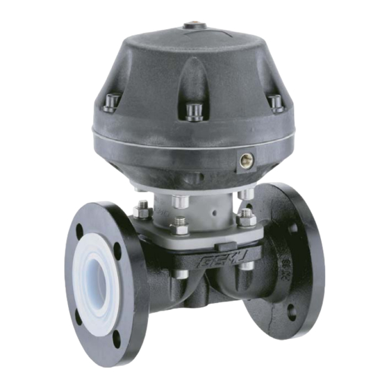
Seite 8: Funktionsbeschreibung
Funktionsbeschreibung 11 Montage und Bedienung GEMÜ 687 ist ein Metall-Membranventil mit Vor Einbau: Durchgangs-, T- oder Behälterboden-Ablass- Ventilkörper- und Membranwerkstoff körper bzw. Ausführung in Mehrwegeausfüh- entsprechend Betriebsmedium auslegen. rung. Das Ventil besitzt einen wartungsarmen Eignung vor Einbau prüfen! Membranantrieb, der mit neutralen Gasen Siehe Kapitel 6 "Technische Daten". - Seite 9 Installationsort: Montage bei Clampanschluss: Bei Montage der Clampanschlüsse VORSICHT entsprechende Dichtung zwischen Ventilkörper und Rohranschluss einlegen Ventil äußerlich nicht stark beanspruchen. und mit Klammer verbinden. Die Dichtung Installationsort so wählen, dass Ventil sowie die Klammer der Clampanschlüsse nicht als Steighilfe genutzt werden kann. sind nicht im Lieferumfang enthalten.
-
Seite 10: Steuerfunktionen
11.2 Steuerfunktionen Anschlüsse Steuer- Folgende Steuerfunktionen sind verfügbar: funktion 1 (NC) Steuerfunktion 1 2 (NO) Federkraft geschlossen (NC): 3 (DA) Ruhezustand des Ventils: durch Federkraft geschlossen. Ansteuern Antriebs + = vorhanden / - = nicht vorhanden (Anschlüsse 2 / 4 siehe Bilder links) (Anschluss 2) öff... -
Seite 11: Montage / Demontage Von Ersatzteilen
12 Montage / Demontage 12.2 Demontage Membrane von Ersatzteilen Wichtig: Vor Demontage der Membrane bitte Antrieb demontieren, siehe "Demontage Ventil (Antrieb vom Körper lösen)". 1. Membrane herausschrauben. 2. Alle Teile von Produktresten und Verschmutzungen reinigen. Teile dabei nicht zerkratzen oder beschädigen! 3. - Seite 12 Membrangröße 80 (DN 65 - 80): Wichtig: Ist die Membrane nicht weit genug Druckstück und Antriebsfl ansch von unten in das Verbindungsstück einge- gesehen: schraubt, wirkt die Schließkraft direkt auf den Schraubpin und nicht über das Druckstück. Das führt zu Beschädigungen und frühzeitigem Ausfall der Membrane und Undicht- heit des Ventils.
-
Seite 13: Montage Der Konkav-Membrane
12.3.2 Montage der Konkav-Membrane Druckstückaussparung Membranschild Schraubpin Schraubpin 5. Neue Stützmembrane auf Druckstück aufl egen. 6. Membranschild auf Stützmembrane Membrandom aufl egen. 1. Antrieb A in Geschlossen-Position 7. Membranschild von Hand fest bringen. in Druckstück einschrauben. 2. Bei Membrangröße 25-80 (DN 15-80) Der Membrandom muss in der Druckstück lose auf Ventilspindel Druckstückaussparung liegen. -
Seite 14: Montage Antrieb Auf Ventilkörper
12.4 Montage Antrieb VORSICHT auf Ventilkörper Gegen Leckage vorbeugen! 1. Antrieb A in Off en-Position bringen. Schutzmaßnahmen gegen Überschrei- 2. Antrieb A mit montierter Membrane 2 tung des maximal zulässigen Drucks auf Ventilkörper 1 aufsetzen, auf durch eventuelle Druckstöße (Wasser- Übereinstimmung von Membransteg und schläge) vorsehen. -
Seite 15: Demontage
1. Geeignete Schutzausrüstung gemäß Hinweis zur Rücksendung: den Regelungen des Anlagenbetreibers Aufgrund gesetzlicher berücksichtigen. Bestimmungen zum Schutz 2. Anlage bzw. Anlagenteil stilllegen. der Umwelt und des Personals 3. Gegen Wiedereinschalten sichern. ist es erforderlich, dass Sie die 4. Anlage bzw. Anlagenteil drucklos Erklärung (anbei) vollständig schalten. -
Seite 16: Fehlersuche / Störungsbehebung
19 Fehlersuche / Störungsbehebung Fehler Möglicher Grund Fehlerbehebung Steuermedium entweicht aus Entlüftungsbohrung* im Oberteil des Antriebs bei Steuerfunktion Steuermembrane defekt Antrieb austauschen 1 (NC) bzw. Anschluss 2 (siehe Kapitel 11.2 " Steuerfunktionen") bei Steuerfunktion 2 (NO) Steuermedium entweicht aus Antrieb austauschen und Steuermedium Spindelabdichtung undicht Leckagebohrung* auf Verschmutzungen untersuchen... -
Seite 17: Schnittbild Und Ersatzteile
20 Schnittbild und Ersatzteile Entlüftungs- bohrung Steuer- membrane Leckagebohrung Pos. Benennung Bestellbezeichnung Ventilkörper K600... Membrane 600...M Schraube Scheibe 687...S30... Mutter Antrieb 9687... 687_us 17 / 40... -
Seite 18: Einbauerklärung
29.12.2009 Projektnummer: MV-Pneum-2009-12 Handelsbezeichnung: Typ 687 Es wird erklärt, dass die folgenden grundlegenden Anforderungen der Maschinenrichtlinie 2006/42/EG erfüllt sind: 1.1.3.; 1.1.5.; 1.1.7.; 1.2.1.; 1.3.; 1.3.2.; 1.3.3.; 1.3.4.; 1.3.7.; 1.3.9.; 1.5.3.; 1.5.5.; 1.5.6.; 1.5.7.; 1.5.8.; 1.5.9.; 1.6.5.; 2.1.1.; 3.2.1.; 3.2.2.; 3.3.2.; 3.4.4.; 3.6.3.1.; 4.1.2.1.; 4.1.2.3.; 4.1.2.4.; 4.1.2.5.; 4.1.2.6. a); 4.1.2.6. b);... -
Seite 19: Eg-Konformitätserklärung
GEMÜ Gebr. Müller GmbH & Co. KG Fritz-Müller-Straße 6-8 D-74653 Ingelfi ngen erklären, dass unten aufgeführte Armaturen die Sicherheitsanforderungen der Druckgeräte- richtlinie 97/23/EG erfüllen. Benennung der Armaturen - Typenbezeichnung Membranventil GEMÜ 687 Benannte Stelle: TÜV Rheinland Berlin Brandenburg Nummer: 0035 Zertifi kat-Nr.: 01 202 926/Q-02 0036 Konformitätsbewertungsverfahren:... - Seite 40 VENTIL-, MESS- UND REGELSYSTEME VALVES, MEASUREMENT AND CONTROL SYSTEMS GEMÜ Gebr. Müller Apparatebau GmbH & Co. KG · Fritz-Müller-Str. 6-8 · D-74653 Ingelfi ngen-Criesbach Telefon +49(0)7940/123-0 · Telefax +49(0)7940/123-192 · info@gemue.de · www.gemue.de...