Gemü 687 Betriebsanleitung
Vorschau ausblenden
Andere Handbücher für 687:
- Original einbau- und montageanleitung (48 Seiten) ,
- Betriebsanleitung (44 Seiten) ,
- Montageanleitung (40 Seiten)

Verwandte Anleitungen für Gemü 687


Inhaltszusammenfassung für Gemü 687
- Seite 1 GEMÜ 687 Pneumatisch betätigtes Membranventil Pneumatically operated diaphragm valve Betriebsanleitung Operating instructions Weitere Informationen Webcode: GW-687...
- Seite 2 Alle Rechte, wie Urheberrechte oder gewerbliche Schutzrechte, werden ausdrücklich vorbehalten. All rights including copyrights or industrial property rights are expressly reserved. Dokument zum künftigen Nachschlagen aufbewahren. Keep the document for future reference. © GEMÜ Gebr. Müller Apparatebau GmbH & Co. KG 15.11.2023 GEMÜ 687 2 / 88 www.gemu-group.com...
-
Seite 3: Inhaltsverzeichnis
14.2 Steuerfunktion 2 ..........14.3 Steuerfunktion 3 ..........15 Fehlerbehebung ........... 16 Inspektion und Wartung ........16.1 Ersatzteile ............16.2 Montage / Demontage von Ersatzteilen ..16.2.1 Demontage Ventil (Antrieb vom Körper lösen) ........www.gemu-group.com 3 / 88 GEMÜ 687... -
Seite 4: Allgemeines
Warnhinweise sind dabei immer mit einem Signalwort und teilweise auch mit einem gefahrenspezifischen Symbol ge- kennzeichnet. Folgende Signalwörter bzw. Gefährdungsstufen werden einge- setzt: GEFAHR Unmittelbare Gefahr! ▶ Bei Nichtbeachtung drohen schwerste Verletzungen oder Tod. GEMÜ 687 4 / 88 www.gemu-group.com... -
Seite 5: Sicherheitshinweise
Abstim- Membrane mung mit dem Hersteller durchführen. (siehe Conexo-Info) CONEXO RFID-Chip Bei Unklarheiten: Körper 15. Bei nächstgelegener GEMÜ Verkaufsniederlassung nach- (siehe Conexo-Info) fragen. CONEXO RFID-Chip An- trieb (siehe Conexo-Info) www.gemu-group.com 5 / 88 GEMÜ 687... -
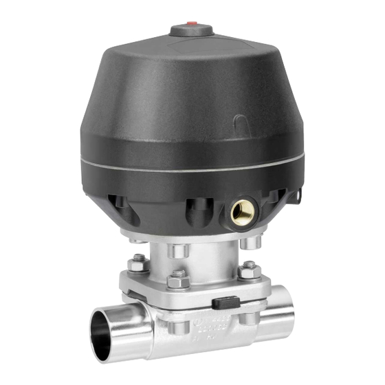
Seite 6: Beschreibung
4 GEMÜ CONEXO 3.2 Beschreibung 4 GEMÜ CONEXO Das Zusammenspiel von Ventilkomponenten, die mit RFID- Das 2/2-Wege-Membranventil GEMÜ 687 verfügt über einen Chips versehen sind und eine dazugehörige IT-Infrastruktur, wartungsarmen Kunststoff-Membranantrieb und wird pneu- erhöht aktiv die Prozesssicherheit. matisch betätigt. Das Ventil besitzt ein Zwischenstück aus Metall. -
Seite 7: Bestelldaten
Stutzen ANSI/ASME B36.19M Schedule 5s Feingussmaterial Stutzen ANSI/ASME B36.19M Schedule 40s 1.4408, Feinguss Gewindeanschluss 1.4408, PFA-Auskleidung Gewindemuffe DIN ISO 228 1.4435, Feinguss NPT Innengewinde Schmiedematerial Gewindestutzen DIN 11851 1.4435 (F316L), Schmiedekörper Kegelstutzen und Überwurfmutter DIN 11851 www.gemu-group.com 7 / 88 GEMÜ 687... - Seite 8 Ra max. 0,64 µm (25 µin.) für medienberührte Antriebsgröße 4/N Oberflächen, Antriebsgröße 4RN gemäß ASME BPE SF6, Antriebsgröße 6A innen/außen elektropoliert Antriebsgröße 6A2 10 Sonderausführung Code DN 100, Membrangröße 100 Ohne Antriebsgröße 5/N BELGAQUA-Zertifizierung Antriebsgröße 5RN Sonderausführung für 3A GEMÜ 687 8 / 88 www.gemu-group.com...
-
Seite 9: Bestellbeispiel
In Ruhestellung geschlossen (NC) 8 Antriebsausführung Antriebsgröße F/N 9 Oberfläche 1503 Ra ≤ 0,8 µm (30 µin.) für medienberührte Oberflächen, gemäß DIN 11866 HE3, innen/außen elektropoliert 10 Sonderausführung Sonderausführung für 3A 11 CONEXO ohne www.gemu-group.com 9 / 88 GEMÜ 687... -
Seite 10: Technische Daten
Ventilanordnung bewährt: Sitzventil zum Absperren von Dampfleitungen und Membran- ventil als Schnittstelle zu den Prozessleitungen. Dampfeingang Prozessleitung Dampfverteilung steriler Prozess Umgebungstemperatur: 0 — 60 °C Steuermedientemperatur: 0 — 40 °C Lagertemperatur: 0 — 40 °C GEMÜ 687 10 / 88 www.gemu-group.com... -
Seite 11: Druck
3,0 max. 3,0 4,0 - 7,0 5/N, 5RN 5,5 - 7,0 max. 5,0 max. 4,5 max. 3,5 max. 3,5 4,5 - 7,0 MG = Membrangröße Sämtliche Druckwerte sind in bar - Überdruck angegeben. www.gemu-group.com 11 / 88 GEMÜ 687... - Seite 12 7 Technische Daten Steuerdruck: GEMÜ 687: Steuerdruck – Betriebsdruck – Diagramm – Steuerfunktion 2 und 3 PTFE-Membrane MG 10 MG 25 MG 100 MG 40 MG 80 MG 50 Betriebsdruck [bar] Betriebsdruck [bar] Elastomer-Membrane MG 10 MG 80 MG 100...
- Seite 13 Drehmomenten mit denen diese angezogen werden. Dadurch können die Kv-Werte über die To- leranzgrenze der Norm hinaus abweichen. Die Kv-Wert-Kurve (Kv-Wert in Abhängigkeit vom Ventilhub) kann je nach Membranwerkstoff und Einsatzdauer variieren. www.gemu-group.com 13 / 88 GEMÜ 687...
-
Seite 14: Produktkonformitäten
USP* Class VI Trinkwasser: Belgaqua* * je nach Ausführung und / oder Betriebsparametern SIL: Produktbeschreibung: Membranventil GEMÜ 687 Gerätetyp: Sicherheitsfunktion: Durch die Sicherheitsfunktion wird das Membranventil in die Geschlossen-Position (bei Steuerfunktion1) oder Of- fen-Position (bei Steuerfuktion 2) gebracht. HFT (Hardware Failure Tolerance):... - Seite 15 2,20 10,30 2,30 8,60 9,22 10,20 8,90 8,00 9,20 13,80 8,50 24,10 20,80 24,80 Gewichte in kg MG = Membrangröße Einbaulage: beliebig Drehwinkel für eine entleerungsoptimierte Montage beachten. Siehe separates Dokument „Technische Information Drehwinkel“. www.gemu-group.com 15 / 88 GEMÜ 687...
-
Seite 16: Abmessungen
H/M, H/N, HRM, 171,0 208,0 75,0 G 1/4 J/M, J/N, JRM, 211,0 244,0 90,0 G 1/4 4/N, 4RN 259,0 368,0 173,0 G 1/4 360,0 475,0 158,0 G 1/4 5/N, 5RN 259,0 372,0 169,0 G 1/4 GEMÜ 687 16 / 88 www.gemu-group.com... - Seite 17 HRM, HRN J/M, J/N, 211,0 206,0 90,0 47,0 G 1/4 JRM, JRN 4/N, 4RN 258,0 282,0 170,0 45,0 G 1/4 360,0 323,0 158,0 110,0 G 1/4 5/N, 5RN 258,0 278,0 165,0 45,0 G 1/4 www.gemu-group.com 17 / 88 GEMÜ 687...
-
Seite 18: Körpermaße
Code 60: Stutzen ISO 1127 / DIN EN 10357 Serie C (Ausgabe 2014) / DIN 11866 Reihe B 2) Werkstoff Ventilkörper Code 40: 1.4435 (F316L), Schmiedekörper Code 42: 1.4435 (BN2), Schmiedekörper, Δ Fe < 0,5 % Code F4: 1.4539, Schmiedekörper GEMÜ 687 18 / 88 www.gemu-group.com... - Seite 19 Code 17: Stutzen EN 10357 Serie A / DIN 11866 Reihe A ehemals DIN 11850 Reihe 2 Code 60: Stutzen ISO 1127 / DIN EN 10357 Serie C (Ausgabe 2014) / DIN 11866 Reihe B 2) Werkstoff Ventilkörper Code C3: 1.4435, Feinguss www.gemu-group.com 19 / 88 GEMÜ 687...
- Seite 20 Code 64: Stutzen ANSI/ASME B36.19M Schedule 5s Code 65: Stutzen ANSI/ASME B36.19M Schedule 40s 2) Werkstoff Ventilkörper Code 40: 1.4435 (F316L), Schmiedekörper Code 42: 1.4435 (BN2), Schmiedekörper, Δ Fe < 0,5 % Code F4: 1.4539, Schmiedekörper GEMÜ 687 20 / 88 www.gemu-group.com...
- Seite 21 Maße in mm MG = Membrangröße 1) Anschlussart Code 59: Stutzen ASME BPE / DIN EN 10357 Serie C (ab Ausgabe 2022) / DIN 11866 Reihe C 2) Werkstoff Ventilkörper Code C3: 1.4435, Feinguss www.gemu-group.com 21 / 88 GEMÜ 687...
- Seite 22 Code 36: Stutzen JIS-G 3459 Schedule 10s Code 37: Stutzen SMS 3008 2) Werkstoff Ventilkörper Code 40: 1.4435 (F316L), Schmiedekörper Code 42: 1.4435 (BN2), Schmiedekörper, Δ Fe < 0,5 % Code C3: 1.4435, Feinguss Code F4: 1.4539, Schmiedekörper GEMÜ 687 22 / 88 www.gemu-group.com...
- Seite 23 NPT 1½ 17,0 2" 71,3 36,3 165,0 NPT 2 18,0 Maße in mm MG = Membrangröße n = Anzahl der Schlüsselflächen 1) Anschlussart Code 31: NPT Innengewinde 2) Werkstoff Ventilkörper Code 37: 1.4408, Feinguss www.gemu-group.com 23 / 88 GEMÜ 687...
- Seite 24 Rd 110 x 1/4 Maße in mm MG = Membrangröße 1) Anschlussart Code 6: Gewindestutzen DIN 11851 2) Werkstoff Ventilkörper Code 40: 1.4435 (F316L), Schmiedekörper Code 42: 1.4435 (BN2), Schmiedekörper, Δ Fe < 0,5 % GEMÜ 687 24 / 88 www.gemu-group.com...
- Seite 25 Rd 110 x 1/4 Maße in mm MG = Membrangröße 1) Anschlussart Code 6K: Kegelstutzen und Überwurfmutter DIN 11851 2) Werkstoff Ventilkörper Code 40: 1.4435 (F316L), Schmiedekörper Code 42: 1.4435 (BN2), Schmiedekörper, Δ Fe < 0,5 % www.gemu-group.com 25 / 88 GEMÜ 687...
- Seite 26 Code 18: EN-GJS-400-18-LT (GGG 40.3), PP-Auskleidung Code 39: 1.4408, PFA-Auskleidung Code 40: 1.4435 (F316L), Schmiedekörper Code 42: 1.4435 (BN2), Schmiedekörper, Δ Fe < 0,5 % Code 83: EN-GJS-400-18-LT (GGG 40.3), Hartgummi-Auskleidung Code C3: 1.4435, Feinguss GEMÜ 687 26 / 88 www.gemu-group.com...
-
Seite 27: Flansch Jis (Code 34)
MG = Membrangröße 1) Anschlussart Code 34: Flansch JIS B2220, 10K, RF, Baulänge FTF EN 558 Reihe 1, ISO 5752, basic series 1, Baulänge nur bei Gehäuseform D 2) Werkstoff Ventilkörper Code 39: 1.4408, PFA-Auskleidung www.gemu-group.com 27 / 88 GEMÜ 687... - Seite 28 Code 38: Flansch ANSI Class 150 RF, Baulänge FTF MSS SP-88, Baulänge nur bei Gehäuseform D 2) Werkstoff Ventilkörper Code 17: EN-GJS-400-18-LT (GGG 40.3), PFA-Auskleidung Code 18: EN-GJS-400-18-LT (GGG 40.3), PP-Auskleidung Code 39: 1.4408, PFA-Auskleidung Code 83: EN-GJS-400-18-LT (GGG 40.3), Hartgummi-Auskleidung GEMÜ 687 28 / 88 www.gemu-group.com...
- Seite 29 Code 18: EN-GJS-400-18-LT (GGG 40.3), PP-Auskleidung Code 39: 1.4408, PFA-Auskleidung Code 40: 1.4435 (F316L), Schmiedekörper Code 42: 1.4435 (BN2), Schmiedekörper, Δ Fe < 0,5 % Code 83: EN-GJS-400-18-LT (GGG 40.3), Hartgummi-Auskleidung Code C3: 1.4435, Feinguss www.gemu-group.com 29 / 88 GEMÜ 687...
- Seite 30 Code 8T: Clamp DIN 32676 Reihe C, Baulänge FTF EN 558 Reihe 7, Baulänge nur bei Gehäuseform D 2) Werkstoff Ventilkörper Code 40: 1.4435 (F316L), Schmiedekörper Code 42: 1.4435 (BN2), Schmiedekörper, Δ Fe < 0,5 % Code F4: 1.4539, Schmiedekörper GEMÜ 687 30 / 88 www.gemu-group.com...
- Seite 31 Code 8E: Clamp ISO 2852 für Rohr ISO 2037, Clamp SMS 3017 für Rohr SMS 3008 Baulänge FTF EN 558 Reihe 7, Baulänge nur bei Gehäuse- form D 2) Werkstoff Ventilkörper Code 40: 1.4435 (F316L), Schmiedekörper Code 42: 1.4435 (BN2), Schmiedekörper, Δ Fe < 0,5 % Code F4: 1.4539, Schmiedekörper www.gemu-group.com 31 / 88 GEMÜ 687...
-
Seite 32: Herstellerangaben
GEMÜ Produkten und deren Ersatzteilen in einem schläge) vorsehen. Raum lagern. HINWEIS Eignung des Produkts! ▶ Das Produkt muss für die Betriebsbedingungen des Rohr- leitungssystems (Medium, Mediumskonzentration, Tem- peratur und Druck) sowie die jeweiligen Umgebungs- bedingungen geeignet sein. GEMÜ 687 32 / 88 www.gemu-group.com... -
Seite 33: Einbaulage
6. Dichtungen zentrieren. 7. Ventilflansch und Rohrflansch mit geeignetem Dichtmittel und passenden Schrauben verbinden. 8. Alle Flanschbohrungen nutzen. 9. Schrauben über Kreuz anziehen. 10. Alle Sicherheits- und Schutzeinrichtungen wieder anbrin- gen bzw. in Funktion setzen. www.gemu-group.com 33 / 88 GEMÜ 687... -
Seite 34: Einbau Mit Gewindemuffe
Antriebs bewirkt das Öffnen des Ventils durch Federkraft. Steuerfunktion 3 Beidseitig angesteuert (DA): Ruhezustand des Ventils: keine definierte Grundposition. Öff- nen und Schließen des Ventils durch Ansteuern der entspre- chenden Steuermediumanschlüsse (Anschluss 2: Öffnen / An- schluss 4: Schließen). GEMÜ 687 34 / 88 www.gemu-group.com... -
Seite 35: Steuermedium Anschließen
Gewinde der Steuermediumanschlüsse: G1/4 ð Das Produkt ist einsatzbereit. 3. Das Produkt in Betrieb nehmen. Steuerfunktion Anschlüsse 4. Inbetriebnahme der Antriebe gemäß beiliegender Anlei- Federkraft geschlossen 2: Steuermedium (Öffnen) tung. (NC) Federkraft geöffnet (NO) 4: Steuermedium (Schließen) www.gemu-group.com 35 / 88 GEMÜ 687... -
Seite 36: Betrieb
ð Produkt öffnet sich. 14.3 Steuerfunktion 3 Das Produkt hat im Ruhezustand keine definierte Grundpositi- 1. Antrieb über Steuermediumanschluss 2 ansteuern. ð Produkt öffnet sich. 2. Antrieb über Steuermediumanschluss 4 ansteuern. ð Produkt schließt sich. GEMÜ 687 36 / 88 www.gemu-group.com... -
Seite 37: Fehlerbehebung
Einbau Ventilkörper in Rohrleitung prüfen undicht Gewindeanschlüsse / Verschraubungen Gewindeanschlüsse / Verschraubungen lose festziehen Dichtmittel defekt Dichtmittel ersetzen Ventilkörper undicht Ventilkörper undicht oder korrodiert Ventilkörper auf Beschädigungen prüfen, ggf. Ventilkörper tauschen * siehe Kapitel "Ersatzteile" www.gemu-group.com 37 / 88 GEMÜ 687... -
Seite 38: Inspektion Und Wartung
Fachpersonal durchführen. Code 5M 2. Geeignete Schutzausrüstung gemäß den Regelungen des 18, 19, 20 Verschraubungsset 687 S30 Anlagenbetreibers tragen. 16.2 Montage / Demontage von Ersatzteilen 3. Anlage bzw. Anlagenteil stilllegen. 4. Anlage bzw. Anlagenteil gegen Wiedereinschalten sichern. 16.2.1 Demontage Ventil (Antrieb vom Körper lösen) 5. -
Seite 39: Demontage Membrane
▶ Das Druckstück ist bei Membrangröße 10-80 lose. Membrangröße 10 (DN 10-20) Druckstück und Antriebsflansch von unten gesehen: Druckstück lose auf Antriebsspindel aufsetzen, Aussparungen D in Führungen C einpassen. Das Druckstück muss sich frei zwischen den Führungen bewegen lassen. www.gemu-group.com 39 / 88 GEMÜ 687... -
Seite 40: Konvex-Membrane Montieren
8. Beim Verspüren eines deutlichen Widerstands Membrane triebs-Lochbild übereinstimmt. soweit zurückschrauben, bis Membran-Lochbild mit An- triebs-Lochbild übereinstimmt. 10. Membranschild von Hand fest auf die Stützmembrane drü- cken, so dass er zurückklappt und an der Stützmembrane anliegt. GEMÜ 687 40 / 88 www.gemu-group.com... -
Seite 41: Montage Antrieb Auf Ventilkörper
ßenwölbung erkennbar. Achtung: Bei der Membrane Code 5M (Konvexe Mem- brane) muss das PTFE-Membranschild und die EPDM- Stützmembrane plan und parallel am Ventilkörper an- liegen. 8. Komplett montiertes Ventil auf Funktion und Dichtheit prü- fen. www.gemu-group.com 41 / 88 GEMÜ 687... -
Seite 42: Rücksendung
Produkt keine Rücksendeerklärung bei, erfolgt keine Gut- schrift bzw. keine Erledigung der Reparatur, sondern eine kos- tenpflichtige Entsorgung. 1. Das Produkt reinigen. 2. Rücksendeerklärung bei GEMÜ anfordern. 3. Rücksendeerklärung vollständig ausfüllen. 4. Das Produkt mit ausgefüllter Rücksendeerklärung an GEMÜ schicken. GEMÜ 687 42 / 88 www.gemu-group.com... - Seite 43 29.12.2009 Projektnummer: MV-Pneum-2009-12 Handelsbezeichnung: Typ 687 Es wird erklärt, dass die folgenden grundlegenden Anforderungen der Maschinenrichtlinie 2006/42/EG erfüllt sind: 1.1.3.; 1.1.5.; 1.2.1.; 1.3.; 1.3.2.; 1.3.3.; 1.3.4.; 1.3.7.; 1.3.9.; 1.5.3.; 1.5.5.; 1.5.6.; 1.5.7.; 1.5.8.; 1.5.9.; 1.6.5. Ferner wird erklärt, dass die speziellen technischen Unterlagen gemäß Anhang VII Teil B erstellt wurden.
-
Seite 44: Konformitätserklärung
GEMÜ Gebr. Müller Apparatebau GmbH & Co. KG Fritz-Müller-Straße 6-8 D-74653 Ingelfingen erklären, dass unten aufgeführte Armaturen die Sicherheitsanforderungen der Druckgeräte- richtlinie 2014/68/EU erfüllen. Benennung der Armaturen - Typenbezeichnung Membranventil GEMÜ 687 Benannte Stelle: TÜV Rheinland Industrie Service GmbH Nummer: 0035 Zertifikat-Nr.: 01 202 926/Q-02 0036... - Seite 87 GEMÜ 687 87 / 88 www.gemu-group.com...
- Seite 88 GEMÜ Gebr. Müller Apparatebau GmbH & Co. KG Fritz-Müller-Straße 6-8, 74653 Ingelfingen-Criesbach, Germany Änderungen vorbehalten Phone +49 (0) 7940 1230 · info@gemue.de Subject to alteration www.gemu-group.com 11.2023 | 88245874...