Werbung
Quicklinks
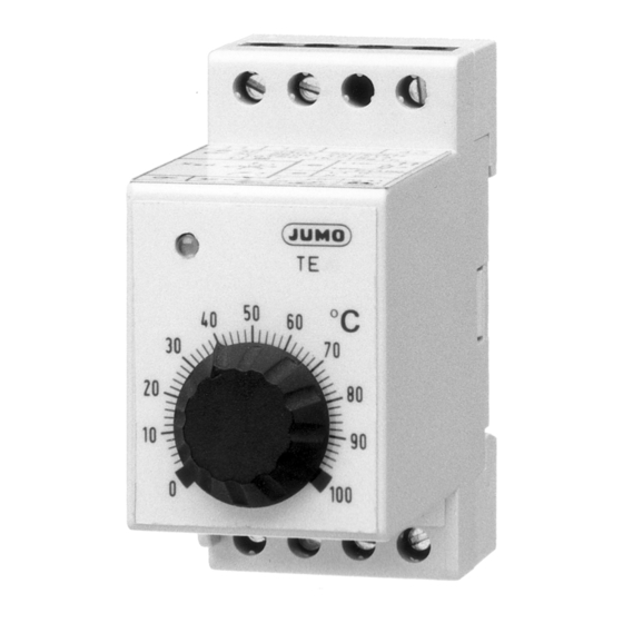
Elektronischer Thermostat TE
B 60.5511
Betriebsanleitung
02.01/00089233
Lesen Sie diese Betriebsanleitung, bevor Sie das Gerät in Betrieb neh-
men. Bewahren Sie die Betriebsanleitung an einem für alle Benutzer je-
derzeit zugänglichen Platz auf. Bitte unterstützen Sie uns, diese
Betriebsanleitung zu verbessern. Für Ihre Anregungen sind wir dankbar.
Telefon 0661 6003-716
Alle erforderlichen Einstellungen und nötigenfalls Eingriffe im Gerätein-
nern sind in der vorliegenden Betriebsanleitung beschrieben. Sollten
trotzdem bei der Inbetriebnahme Schwierigkeiten auftreten, bitten wir Sie,
keine unzulässigen Manipulationen am Gerät vorzunehmen. Sie gefähr-
den dadurch Ihren Garantieanspruch! Bitte setzen Sie sich mit der näch-
sten Niederlassung oder mit dem Stammhaus in Verbindung.
Beschreibung
Konstruktive Einzelheiten
( 1 ) Schaltdifferenz X
– Trimmer
sd
( 2 ) Nullpunktkorrektur – Trimmer
( 3 ) Schaltstellungsanzeige
( 4 ) Sollwertsteller
Begrenzung des Sollwertbereiches
Der max. einstellbare Sollwert kann mit einem verstellbaren Anschlag, der
sich unter dem Sollwertsteller ( 4 ) befindet, im Raster von 10% des Re-
gelbereichumfanges nach unten verändert werden.
✱
Sollwertsteller ( 4 ) mit zwei Schraubendrehern, die an den beiden
gegenüberliegenden Aussparungen am Sollwertsteller ( 4 ) anzuset-
zen sind, gleichmäßig abhebeln.
✱
Anschlag abnehmen und mit dem Pfeilsymbol auf gewünschten
Wert zeigend wieder einsetzen.
✱
Sollwertsteller ( 4 ) unter Beachtung der Position von Knopfachse zu
Trimmer im Gerät in Gehäuse eindrücken.
Schaltdifferenzeinstellung
Die werkseitig auf Minimalwert eingestellte Schaltdifferenz (X
Bedarf mit einem Schraubendreher am Schaltdifferenz -Trimmer ( 1 ) von
0,25 ... 5% des Regelbereichsumfanges verstellt werden.
Auf einer Skala mit Markierungen von 0 ... 5, die etwa den %-Angaben der
X
-Einstellung entsprechen, ist eine schnelle Grobeinstellung möglich.
sd
Typ TE-1 ... O
Ausschaltpunkt bei x = w
Einschaltpunkt bei x = w-x
Typ TE-1 ... S
Ausschaltpunkt bei x = w
Einschaltpunkt bei x = w+x
Soll x
genau eingestellt werden:
sd
✱
Ausschaltpunkt durch langsames Drehen des Sollwertstellers ( 4 )
nach links (bzw. rechts bei TE-1 ... S) feststellen.
✱
x
-Trimmer ( 1 ) auf Maximalwert stellen.
sd
✱
Sollwert am Sollwertsteller ( 4 ) um den Wert der gewünschten
Schaltdifferenz höher (bzw. niedriger bei TE-1 ... S) einstellen.
✱
x
-Trimmer ( 1 ) zurückdrehen bis das Gerät schaltet und Schalt-
sd
stellungsanzeige ( 3 ) aufleuchtet.
✱
Durch langsames Drehen des Sollwertstellers ( 4 ) kann der Ein- und
Ausschaltpunkt kontrolliert werden.
Nullpunktkorrektur
Für die genaue Anpassung des Schaltpunktes an die Einsatzbedingungen
des Anwenders (Umgebungstemperatur, Fühlerleitung usw.) ist eine Refe-
renztemperatur am Fühlereingang des Gerätes erforderlich.
Die Angleichung erfolgt mit einem Schraubendreher am Nullpunktkorrek-
turtrimmer ( 2 ) und verschiebt den Schaltpunkt im gesamten Regelbe-
reich um den korrigierten Differenzwert.
Der Verstellbereich beträgt mindestens ± 10% des jeweiligen Regelberei-
chumfanges.
Messkreisüberwachung
Messwertgeber
Fühler-/Leitungskurzschluss Fühler-/Leitungsbruch
t
w
Beim Auftreten eines Fehlers schaltet das Relais in Ruhestellung, d.h.
Kontakt 42-43 geöffnet.
Bei Widerstandsthermometer Pt 100 spricht die
Regelbereich
Fühlerkurzschlussüberwachung an bei einer Fühler-
temperatur unter:
-50 ... +030°C
-20 ... +040°C
0 ... +040°C
0 ... +050°C
0 ... +100°C
0 ... +150°C
0 ... +200°C
0 ... +300°C
0 ... +400°C
0 ... +500°C
Allgemeine Kennwerte
Schaltpunktgenauigkeit
zul. Umgebungstemperatur
Umgebungstemperatureinfluss < 0,5%/10K
Leistungsaufnahme
Schaltleistung
Telefax 0661 6003-504
) kann bei
sd
sd
sd
- - -
•
•
•
-085°C
-045°C
-025°C
-040°C
-065°C
-085°C
-130°C
-165°C
-165°C
-225°C
± 2% vom Regelbereichsumfang
im Betrieb:
-10 ... +50°C
bei Lagerung: -40 ... +75°C
max. 3 VA
AC 250 V, 10 A
DC 24 V, 10 A
Electronic thermostat TE
Please read these Operating Instructions before commissioning the in-
strument. Keep the operating instructions in a place which is accessible
to all users at all times. Please assist us to improve these operating in-
structions where necessary. Your suggestions will be welcome.
Phone:
in Germany 0661 6003-716
abroad +49 661 6003-0
All necessary settings and possible adjustments inside the unit are de-
scribed in these operating instructions. However, if any difficulties should
arise during commissioning, you are asked not to carry out any unautho-
rized manipulations on the unit. You could endanger your rights under the
instrument warranty! Please contact your nearest subsidiary or the main
factory in such a case.
Description
Design features
( 1 ) Trimmer for switching differential X
( 2 ) Trimmer for zero correction
( 3 ) Switching status indication
( 4 ) Setpoint knob
Limiting the setpoint range
The maximum setpoint that can be selected can be limited by means of
an adjustable stop located below the setpoint knob ( 4 ), in 10% down-
ward steps of the range span.
✱
Lever off the setpoint knob ( 4 ) evenly, using two screwdrivers which
are applied to the opposite recesses on the knob ( 4 ).
✱
Remove the stop and replace it – the arrow has to point to the
required value.
✱
Push the knob ( 4 ) back onto the spindle, observing the position of
the spindle relative to the trimmer in the unit.
Setting the switching differential
The switching differential (X
) is set at the factory to the minimum value
sd
and can, if required, be adjusted with a screwdriver on the differential trim-
mer ( 1 ) from 0.25% to 5% of the control span.
Rapid coarse adjustment is possible, using a scale graduated 0 — 5
which corresponds approximately to the differential setting X
Type TE-1 ... O
switch-off point at x = w
switch-on point at x = w-x
Type TE-1 ... S
switch-off point at x = w
switch-on point at x = w+x
For the accurate setting of x
, proceed as follows:
sd
✱
Determine the switch-off point by slowly turning the setpoint knob
( 4 ) anticlockwise (clockwise on the TE-1 ... S).
✱
Set the x
trimmer ( 1 ) to the maximum value.
sd
✱
Increase the setpoint on the knob ( 4 ) by the amount of the required
differential (reduce it by this amount on the TE-1 ... S).
✱
Turn the x
trimmer ( 1 ) back until the unit switches and the
sd
switching status indicator ( 3 ) lights up.
✱
Check the switch-on and switch-off points by slowly rotating the
setpoint knob ( 4 ).
Zero correction
For the accurate adjustment of the switching point to the actual operating
conditions (ambient temperature, probe cable etc.), a reference tempera-
ture is required at the probe input.
The adjustment is made with a screwdriver on the zero correction trimmer
( 2 ) and shifts the switching point over the entire control range by the cor-
rection offset.
The adjustment range is at least ± 10% of the particular control span.
Input circuit monitoring
Transducer
Probe/lead short-circuit
thermocouple (t)
res. therm. (w)
In the event of a fault, the relay is de-energized, i.e. contact 42-43 opens.
With Pt100 resistance thermometers, the probe
Control range
short-circuit monitor responds at a probe
temperature below:
-50 to +030°C
-20 to +040°C
0 to +040°C
0 to +050°C
0 to +100°C
0 to +150°C
0 to +200°C
0 to +300°C
0 to +400°C
0 to +500°C
General data
Switching point accuracy
Perm. ambient temperature
Ambient temperature error
Power consumption
Contact rating
B 60.5511
Operating Instructions
02.01/ 00089233
Fax:
in Germany 0661 6003-504
abroad +49 661 6003-607
sd
in percent.
sd
sd
sd
Probe/lead break
- - -
•
•
•
-085°C
-045°C
-025°C
-040°C
-065°C
-085°C
-130°C
-165°C
-165°C
-225°C
± 2% of control span
in use:
-10 to +50°C
during storage: -40 to +75°C
< 0.5% per 10°C
3 VA max.
10 A, 250 V AC
10 A, 24 V DC
Werbung

Verwandte Anleitungen für JUMO B 60.5511


Inhaltszusammenfassung für JUMO B 60.5511
- Seite 1 Elektronischer Thermostat TE Electronic thermostat TE B 60.5511 B 60.5511 Betriebsanleitung Operating Instructions 02.01/00089233 02.01/ 00089233 Lesen Sie diese Betriebsanleitung, bevor Sie das Gerät in Betrieb neh- Please read these Operating Instructions before commissioning the in- men. Bewahren Sie die Betriebsanleitung an einem für alle Benutzer je- strument.
- Seite 2 ( 2 ) gland DIN 46320, APg11-FS DIN 46320, APg11-FS M. K. JUCHHEIM GmbH & Co M. K. JUCHHEIM GmbH & Co JUMO Instrument Co. Ltd. JUMO PROCESS CONTROL INC. Hausadresse: Street adress: JUMO House 885 Fox Chase, Suite 103 Moltkestraße 13 - 31...