Herunterladen Diese Seite drucken
EOS Bi-O-Tec Montage- Und Gebrauchsanweisung
Vorschau ausblenden Andere Handbücher für Bi-O-Tec:

Werbung

Verfügbare Sprachen

Verfügbare Sprachen

MADE IN GERMANY
Montage- und Gebrauchsanweisung
D
Assembly and operating instruction
GB
Р
RU
IP X4
а
Druck.-Nr 29343369 / 11.12
D
Bi-O Tec
а а
1

Werbung

loading

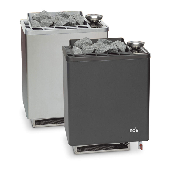
Inhaltszusammenfassung für EOS Bi-O-Tec

  • Seite 1 Bi-O Tec Montage- und Gebrauchsanweisung Assembly and operating instruction Р а а а MADE IN GERMANY IP X4 Druck.-Nr 29343369 / 11.12...
  • Seite 2 Deutsch ..................3 English ..................17 Р ...................31...
  • Seite 3: Inhaltsverzeichnis

    Deutsch Inhalt Bestimmungsgemäße Verwendung ................4 Allgemeine Hinweise ....................4 Wichtige Hinweise ....................5 Elektroanschluss ....................6 Anschlußbeispiel einer Saunaanlage ..............7 Technische Daten ....................8 Mindestabstände ....................8 Finnischer Saunabetrieb ..................9 Betrieb mit Verdampfer ..................10 Entkalken des Verdampfers ..................10 Saunasteine ......................11 Wartung und Pflege ....................11 Zubehör .......................13 Service Adresse: ....................15 Recycling ......................15 Gewährleistung .....................15...
  • Seite 4: Bestimmungsgemäße Verwendung

    Allgemeine Hinweise Sehr geehrte Kundin, sehr geehrter Kunde, Sie haben ein hochwertiges technisches Beachten Sie, dass Sie ein optimales Sauna- Gerät erworben, mit welchem Sie lange Jah- klima nur dann erreichen, wenn die Kabine mit re Freude am Saunabaden haben werden. ihrer Zuluft und Abluft, das Saunaheizgerät Dieses Saunaheizgerät wurde nach den und das Steuergerät aufeinander abgestimmt...
  • Seite 5: Wichtige Hinweise

    Wichtige Hinweise teren Saunawand im unteren Bereich angebracht. Die Be- und Entlüftung darf Bei unsachgemäßer Montage be- nicht verschlossen werden. Bitte beach- steht Brandgefahr! Lesen Sie bit- ten Sie die Hinweise Ihres Saunakabi- diese Montageanleitung sorgfäl- nenlieferanten. tig durch. Beachten Sie besonders die •...
  • Seite 6: Elektroanschluss

    Elektroanschluss • Alle Anschlussleitungen, die im Inneren der Kabine verlegt werden, müssen Silikonlei- Diese Arbeit wird Ihr Elektroinstallateur tungen sein und für eine Umgebungstem- ohne weitere Erklärung gemäß dem v.g. peratur von mindestens 170°C geeignet. Anschlussschema und nach dem in dem Werden als Anschlussleitung einadrige jeweiligen Steuergerät...
  • Seite 7: Anschlußbeispiel Einer Saunaanlage

    Anschlußbeispiel einer Saunaanlage Sensor Saunasteuergerät control unit max. 9 kW max. 3 kW WB WM N N U V W L1 L2 L3 N U V W WB WM N Achtung! Immer Nulleiter N mit anklemmen. 400 V AC 3N 6 kW 7,5 kW 9 kW...
  • Seite 8: Technische Daten

    Mindestabstände Technische Daten Die Mindesthöhe der Saunakabine muss Spannung: 400 V AC 3N 50 Hz innen 1,90 m betragen. Leistungsaufnahme:6,0*; 7,5**; 9,0** kW je Der Abstand zwischen Oberkante Heizge- nach Ausführung rät und Kabinendecke muss mind. 90 cm Verdampferleistung: *1,5; **2,0 kW betragen Kabinenwand Höhe: 760 mm bei 160 mm Bodenabstand...
  • Seite 9: Finnischer Saunabetrieb

    2. Anschlussleitung nach Schaltplan an- 5. Das Saunaheizgerät mittels Blechschraube schließen. Ein Schaltplan ist im An- durch die am hinteren Ofenrand befi ndliche schlussraum angebracht. Bohrung an der Wandhalterung sichern (Abb. 7). 3. Anschlusskasten mit dem Deckel, Ab- standhalter nach außen, verschließen. Verwenden Sie hierzu 2 Stück Blech- schrauben (Abb.
  • Seite 10: Betrieb Mit Verdampfer

    Betrieb mit Verdampfer Durch Zugabe von fremden Aro- mastoffen oder sonstigen Zusatz- (nur bei Öfen mit Verdampfer) mitteln zur Luftbefeuchtung ist ein ge- sundheitliches Risiko nicht auszuschlie- Die Regelung des Verdampfers erfolgt über ßen. Von der Verwendung dieser Zusätze das Steuergerät. Entweder erhalten Sie ei- wird daher abgeraten, es sei denn, sie nen Feuchtewert, der über einen Soll-Ist- werden vom Gerätehersteller oder Sauna-...
  • Seite 11: Saunasteine

    Saunasteine Wartung und Pfl ege Der Saunastein ist ein Naturprodukt. Über- Alle Saunaheizgeräte sind aus korrosions- prüfen Sie die Saunasteine in regelmäßigen armem Material. Damit Sie jedoch lange Abständen. Die Saunasteine können insbe- Freude mit Ihrem Saunaheizgerät haben, sondere durch scharfe Aufgusskonzentrate sollten Sie das Gerät warten und pfl...
  • Seite 12 Bei der Installation von Saunaheizgeräten ist die DIN VDE 0100 Teil 703 zu beach- ten! Diese Norm macht in Ihrer neuesten Ausgabe, gültig seit Februar 2006, unter Änderungen Absatz 703.412.05 folgende Aussage; Zitat: Der zusätzliche Schutz muss für alle Stromkreise der Sauna durch einen oder mehrere Fehler- strom-Schutzeinrichtungen (RCDs) mit einem Be- messungsdifferenzstrom nicht größer als 30 mA...
  • Seite 13: Zubehör

    Zubehör 3. Fügen Sie das Aufnahmerohr mit dem Bolzen in die Bohrung der oberen Quer- Zusätzlich haben Sie bei diesem Ofen die traverse am Dreieckrahmen, so dass Möglichkeit, mit der Aufnahmevorrichtung dieses schwenkbar ist. weitere Wellness-Effekte zu erzielen. Aromawanne Aufnahmerohr Aromatopf 4.
  • Seite 14: Kräutertopf - Halter

    Kräutertopf - Halter Kräutertopf Halter Saunaofen Achtung! Während des Saunabetriebes erhitzt sich die Aufnahmevorrichtung. Fassen Sie daher nie während des Saunabetriebes oder kurz danach die Vorrichtung an - Verbrennungsgefahr. Füllen Sie niemals trockene Kräuter oder Teebeutel in die Zubehörteile ein - Brand- gefahr.
  • Seite 15: Service Adresse

    Verpackung (ACHTUNG: Gefahr von Transport- schäden) an unsere Service-Abteilung einzuschi- Service Adresse cken. Senden Sie das Gerät stets mit diesem ausge- EOS Saunatechnik GmbH füllten Garantieschein ein. Adolf-Weiß-Straße 43 Eventuell entstehende Beförderungskosten für 35759 Driedorf-Mademühlen, Germany die Ein- und Rücksendung können von uns nicht Fon: +49 (0)2775 82-514 übernommen werden.
  • Seite 16: Rücksende-Verfahren (Rma) - Hinweise Für Alle Rücksendungen

    Rücksende-Verfahren (RMA) – Hinweise für alle Rücksendungen! Sehr geehrte Kundin, sehr geehrter Kunde, wir wünschen Ihnen viel Freude mit den bestellten Artikeln. Für den Fall, dass Sie ausnahmsweise einmal nicht ganz zufrieden sein sollten, bitten wir Sie um genaue Beachtung der nachstehenden Ver- fahrensabläufe.
  • Seite 17 English Table of Contents Intended use ......................18 General notes .......................18 Important notes .....................19 Electrical connection ....................20 Example of a properly connected sauna system ..........21 Technical Data ......................22 Minimum clearances .....................22 Finnish sauna operation ..................23 Operation with vaporizer ..................24 De-scaling of the vaporizer ...................24 Sauna stones ......................25 Maintenance and care ..................25 Accessories ......................27...
  • Seite 18: Intended Use

    Dear Customer, For installation and electrical connection of the rocker switch follow the installation in- You have purchased a high quality technical structions supplied with this part. system which will provide you with many ye- ars of enjoyable sauna bathing. This sauna General notes heating system was constructed in accor- dance with state-of-the-art European safety...
  • Seite 19: Important Notes

    Important notes air intake and exhaust vents must not be closed. Please observe the information If assembled incorrectly, the sys- provided by your sauna cabin supplier. tem will present a fi re hazard. • For the adjustment and control of the sau- Please read this installation guide tho- na heating unit, one of the control units roughly.
  • Seite 20: Electrical Connection

    in the table. Electrical connection • During the installation of the sauna hea- Your electrician will be able to accomplish ting unit, make certain that the vertical this work without further explanation in ac- cordance with the provided wiring schema- clearance between the upper edge of the tic and with the help of the circuit diagram sauna heating unit and the sauna ceiling...
  • Seite 22: Example Of A Properly Connected Sauna System

    Example of a properly connected sauna system Sensor Saunasteuergerät control unit max. 9 kW max. 3 kW WB WM N N U V W L1 L2 L3 N U V W WB WM N Caution! Always make certain to include neutral conductor N clamp 400 V AC 3N 6 kW...
  • Seite 23: Technical Data

    Minimum clearances Technical Data The minimum interior height of the sauna Voltage: 400 V AC 3N 50 Hz booth is 1.90 m Power consumption: 6.0*; 7.5**; 9.0** kW When assembling the sauna oven, attention depending on the version must be paid to the fact that the vertical Evaporation capacity: *1.5;...
  • Seite 24: Finnish Sauna Operation

    2. Connect the connection cable per the 5. Fix the sauna oven to the wall bracket by circuit plan. A circuit plan is posted on the means of a sheet-metal screw through the inside of the connection space cover. drilled hole on the back of the oven (Fig. 3.
  • Seite 25: Operation With Vaporizer

    Operation with vaporizer If additives are put in the water, this gene- rally leads to a foamy boiling over of the wa- (only Bi-O heaters) ter. In this case the water must be drained The control of the vaporizer is managed by and the interior of the cold reservoir washed the control unit.
  • Seite 26: Sauna Stones

    Sauna stones Maintenance and care The sauna stone is a natural product. All sauna heating units are made of low- Check the sauna stones at regular intervals. corrosion material. Still, to enjoy your sau- Strong infusion concentrates especially can na heating unit for a long time, you should weaken the sauna stones and cause them to maintain and care for the unit.
  • Seite 27 For the installation of sauna heaters, please pay attention to the DIN VDE 0100 part 703 ! This standard makes the following statement valid in your newest expenditure, since February 2006, paragraph 703.412.05; Quotation: The additional must be planned for all electric cir- cuits of the Sauna by one or more fault current protection device (RCDs) with a calculation diffe- rence stream not more largely than 30 mA, exclu-...
  • Seite 28: Accessories

    Accessories 3. Position the pin on the mounting tube in the hole in the upper cross member on Moreover this stove offers the possibility of the triangular frame so that it can pivot. achieving wellness effects with the mounting device. Aroma pan mounting tube Aroma pan...
  • Seite 29 Herbal cup - mounting Herbal cup Mounting Saunaheater Caution! The mounting device heats up during operation of the sauna. Therefore never touch the device during operation of the sauna or shortly thereafter - danger of severe burns. Never place dry herbs or tea bags in the accessories - fi...
  • Seite 30: Service Address

    Service Address: Outside of Germany please contact your EOS Saunatechnik GmbH specialist dealer in case of warranty claims. Adolf-Weiß-Straße 43 Direct warranty processing with our service 35759 Driedorf-Mademühlen, Germany department is in this case not possible.
  • Seite 31: Handling Procedures For Return Shipments (Rma) - Details For All Returns

    Handling procedures for return shipments (RMA) - Details for all returns ! Dear customer we hope that you will rejoice in the ordered articles. Just in case that you are not entirely contented as an exeption, please follow the procedures specified below.This enabling us to ensure a quick and smooth handling of the return shipment.
  • Seite 32 Р С а П а а ..........32 О а а ....................32 У а а :......................33 П П ............34 П а ..................35 а ...................36 П а ....................36 Р а ..................37 Ра а а ..................38 Ка а ....................39 П а а...
  • Seite 33: П А А

    У а а П а М а а В а а а а а а а В а а а О а а О а а а а О а а а а а а а DIN en, а а а...
  • Seite 34 В а У а а а а а а а П а а а а 5 – 10 а а. М а а а а а а а П а а а, а • В а а а а а а...
  • Seite 35 П П а . В а а а а а а а а а а а а а а а а а а а а 170°C. В а а В а а а а . В а а а а М...
  • Seite 36 П а Sensor Saunasteuergerät control unit max. 9 kW max. 3 kW WB WM N N U V W L1 L2 L3 N U V W WB WM N П а ! В а а а а 400 V AC 3N 6 kW 7,5 kW 9 kW...
  • Seite 37 а П а П а а а а а На : 400 В а, а , а а а , 50 Г а а а а а ( а П : 6,0*; 7,5**; 9,0** ). М а а а В а...
  • Seite 38: П А

    2. П а а . С а а а а а 3. За а а а а Д – а . 4). Р В а а а а а Б -О Т а , а а а ЭОС. а а Д...
  • Seite 39: Ра А А

    Ра а а В а а а а а И а . П а . В а а а а а а а а а а а а а а И - а а Е а а а а , а а...
  • Seite 40: Ка А

    Ка а П а а Ка а – В а а а а . Ч а а а Ва а , а П а а а, а а а . П а а а а а а а И а а...
  • Seite 41 А а 3.Т а а а П а а а а а Ва а а , а а а . Ва а а а а а К а а 4.В а . О а Ва а а а а а а...
  • Seite 42 П а а а а П а а В а !В а а а а а . П а а а а а а а а а – а а. Н а а а а а а а – а а...
  • Seite 43: Га А

    а, а а. П а а а а а а (ВНИМАНИЕ: а а И О а а EOS Saunatechnik GmbH а а а , а 35759 Д -Ма , Г а Т а а а В Г а а а...
  • Seite 44: А А

    П а а а а (RMA) - а а а а У а а а Ва а а а а . В а , В а Ва а а а. Т а а а а . П а а а •...