EOS ECON 45A2 Montage- Und Gebrauchsanweisungen

Verwandte Anleitungen für EOS ECON 45A2


Inhaltszusammenfassung für EOS ECON 45A2
- Seite 1 All manuals and user guides at all-guides.com ECON 45A2 Montage- und Gebrauchsanweisung Assembly and operating instruction Р а а а Made in Germany IP x4 Druck Nr. 29343787 / - 32.12...
-
Seite 3: Inhaltsverzeichnis
All manuals and user guides at all-guides.com Deutsch Inhalt Lieferumfang ......................4 Technische Daten ....................4 Allgemeine Hinweise zum Saunabaden ..............5 Allgemeine Sicherheitsbestimmungen ..............6 Montage des Steuergerätes ...................7 Wandbefestigung ....................7 Elektroanschluss .....................9 Anschluss des Saunaofens ................9 Anschluss der Saunaleuchte ................9 Installationsschema ..................10 Anschluss Saunaheizgerät ................10 Anschluss der Fühlerleitungen ................11 Montage des Ofenfühlers ................11... -
Seite 4: Lieferumfang
All manuals and user guides at all-guides.com Lieferumfang (Änderungen vorbehalten) Zum Lieferumfang des Steuergerätes gehört: 1. Ofenfühlerplatine mit Übertemperatursicherung, KTY-Fühler mit Fühlergehäuse, zwei Stück Be- festigungsschrauben 3 x 25 mm und Fühlerkabel ca. 2,0 m lang. 2. Plastikbeutel mit drei Befestigungsschrauben 4 x 20 mm. 3. -
Seite 5: Allgemeine Hinweise Zum Saunabaden
All manuals and user guides at all-guides.com Allgemeine Hinweise zum Saunabaden Sehr geehrter Kunde, mit diesem Sauna-Steuergerät haben Sie Aus Sicherheitsgründen ist der Temperatur- ein hochwertiges elektronisches Gerät er- fühler mit der Übertemperatursicherung im worben, welches nach den neuesten Nor- Bereich über dem Ofen an der Kabinende- men- und Güterichtlinien entwickelt und ge- cke angeordnet, da sich hier üblicherweise... -
Seite 6: Allgemeine Sicherheitsbestimmungen
All manuals and user guides at all-guides.com Allgemeine Sicherheitsbestimmungen • Dieses Gerät ist nicht dafür bestimmt, • Die Anlage muss bei allen Installations- durch Personen (einschließlich Kinder) und Reparaturarbeiten allpolig vom Netz- mit eingeschränkten physischen, senso- getrennt werden, d.h. Sicherungen bzw. rischen oder geistigen Fähigkeiten oder Hauptschalter ausschalten. -
Seite 7: Montage Des Steuergerätes
All manuals and user guides at all-guides.com sehenen Durchführungen und schrauben Montage des Steuergerätes Sie das Gehäuseunterteil in den beiden Wandbefestigung unteren Bohrungen fest an die Kabinen- wand. Abb. 4 Das Steuergerät darf nur außerhalb der Ka- bine montiert werden. Als Montageort wäh- len Sie zweckmäßigerweise die Kabinen- wand an deren Innenseite der Saunaofen befestigt ist. - Seite 8 All manuals and user guides at all-guides.com Befestigungslöcher oberes Befestigungsloch Abb. 4 Netzzuleitung Zuleitung für Kabi- nenbeleuchtung Lufteintrittsöffnung Abb. 5 Tabelle 1 Ofen- Absicherung Verbindung Verbindung elektr. für Kabinen- leistung Steuergerät Netz - Steuergerät Anschluss volumen nach DIN in A Steuergerät - Ofen 4,5 kW...
-
Seite 9: Elektroanschluss
All manuals and user guides at all-guides.com Elektroanschluss Anschluss des Saunaofens Der elektrische Anschluss darf nur von einem zugelassenen Elektroinstallateur unter Beachtung der Richtlinien des ört- Den Saunaofen entsprechend der Monta- lichen Energieversorgungsunternehmens geanleitung des Herstellers vor die Luftein- und des VDE durchgeführt werden. trittsöffnung montieren. -
Seite 10: Installationsschema
All manuals and user guides at all-guides.com Installationsschema = alternativ ECON 400 V 3 N AC 50 Hz Anschluss Saunaheizgerät ECON 142°C max .9 kW 400 V 3 N AC... -
Seite 11: Anschluss Der Fühlerleitungen
All manuals and user guides at all-guides.com 2. Bohren Sie dafür ein Loch für die Kabel- Anschluss der Fühlerleitungen durchführung, vorzugsweise in die Mitte Die Fühler- und Netzleitungen sollten nicht eines Profi lbrettes. zusammen verlegt oder durch eine gemein- 3. Führen Sie die Fühlerkabel durch das ge- same Durchführung geführt werden. -
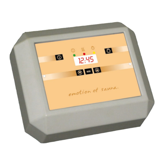
Seite 12: Bedienung
All manuals and user guides at all-guides.com Auf den nun folgenden Seiten wollen wir Sie mit den Bedienelementen und Funktionen Ihrer Saunasteuerung vertraut machen. Die Skizzen neben dem Text zeigen die jeweils sichtba- ren Anzeigen der Steuerung. Die Zeichen bedeuten, dass der so eingerahmte Teil der Anzeige blinkt. -
Seite 13: Erstes Einschalten Des Steuergerätes
All manuals and user guides at all-guides.com Erstes Einschalten des Steuergerätes Nachdem Sie alle Anschlüsse noch einmal überprüft haben -achten Sie darauf, dass der Geräteschalter in der Schaltstellung I ist - nehmen Sie das Gerät ans Netz, indem Sie die Sicherungen bzw. -
Seite 14: Ändern Der Voreingestellten Parameter
All manuals and user guides at all-guides.com Ein-, Ausschalten der Saunaleuchte Durch drücken der - Taste kann die Ka- binenbeleuchtung ein- oder ausgeschaltet werden. In der Anzeige leuchtet zusätzlich 15:00 die gelbe Licht -LED wenn die Beleuchtung eingeschaltet ist. Ändern der voreingestellten Parameter Um die voreingestellten Parameter für Temperatur zu ändern, muß... -
Seite 15: Starten Mit Zeitvorwahl
All manuals and user guides at all-guides.com Möglichkeit 1: Sie möchten die Sauna gleich nutzen Drücken Sie die - Taste. Die eingestellte Temperatur wird gespei- chert, die Sauna schaltet ein und regelt zur neu eingestellten Temperatur Möglichkeit 2: Sie möchten die Sauna später nutzen Zur Speicherung der neu eingestellten Tem- peratur drücken Sie die „MODE“... -
Seite 16: Deaktivieren Der Zeitvorwahl
All manuals and user guides at all-guides.com Drücken Sie die „MODE“ - Taste. Die An- zeige beginnt zu blinken. 19 : 00 Mit den Tasten können Sie jetzt die gewünschte Vorwahlzeit einstellen. Bedenken Sie aber, dass die Kabine ca. 17 : 10 40-50 Minuten aufheizen muss, um ein angenehmes Klima in der Kabine zu errei- chen. -
Seite 17: Ändern Der Aktuellen Uhrzeit
All manuals and user guides at all-guides.com Ändern der aktuellen Uhrzeit (Sommer - Winterzeit) Drücken Sie die oder Taste bis die aktuelle Uhrzeit angezeigt wird. 15:00 Drücken Sie die „MODE“ - Taste. Die An- zeige beginnt zu blinken. 15:00 Mit den Tasten können Sie jetzt die aktuelle Uhrzeiteit einstellen. -
Seite 18: Heizzeiterweiterung
All manuals and user guides at all-guides.com Heizzeiterweiterung (gewerbliche Nutzung) Achtung! Die Anlage muss allpolig vom Netz getrennt werden! Im Lieferzustand ist das Steuergerät auf Jumper eine maximale Heizzeitdauer von 6 Stunden eingestellt. Diese Heizzeitbegrenzung kann auf 12 Stunden verlängert werden. Hierzu wird der Jumper gemäß... -
Seite 19: Fehlersuche / Fehlermeldungen
All manuals and user guides at all-guides.com Fehlersuche / Fehlermeldungen Anzeige / Sym- Ursache Abhilfe ptom KTY-Sensor überprüfen (ca. 2 k Ohm bei Unterbrechung oder 20° C). Leitung (rot) und Verbindungen auf Kurzschluss im Sen- Unterbrechung oder Kurzschluss überprü- sorkreis fen. -
Seite 20: Service Adresse
Verpackung (ACHTUNG: Gefahr von Transport- schäden) an unsere Service-Abteilung einzuschi- cken. Service Adresse Senden Sie das Gerät stets mit diesem ausge- EOS Saunatechnik GmbH füllten Garantieschein ein. Adolf-Weiß-Straße 43 Eventuell entstehende Beförderungskosten für 35759 Driedorf-Mademühlen die Ein- und Rücksendung können von uns nicht Germany übernommen werden. -
Seite 21: Rücksende-Verfahren (Rma) - Hinweise Für Alle Rücksendungen
All manuals and user guides at all-guides.com Rücksende-Verfahren (RMA) – Hinweise für alle Rücksendungen! Sehr geehrte Kundin, sehr geehrter Kunde, wir wünschen Ihnen viel Freude mit den bestellten Artikeln. Für den Fall, dass Sie ausnahmsweise einmal nicht ganz zufrieden sein sollten, bitten wir Sie um genaue Beachtung der nachstehenden Ver- fahrensabläufe.