Futurelight COLOR WAVE Bedienungsanleitung
Led moving bar

Verwandte Anleitungen für Futurelight COLOR WAVE


Inhaltszusammenfassung für Futurelight COLOR WAVE
- Seite 1 BEDIENUNGSANLEITUNG USER MANUAL COLOR WAVE LED moving bar © Copyright Für weiteren Gebrauch aufbewahren! Nachdruck verboten! Keep this manual for future needs! Reproduction prohibited!
-
Seite 2: Inhaltsverzeichnis
Inhaltsverzeichnis EINFÜHRUNG ..............................4 Lieferumfang ..............................4 SICHERHEITSHINWEISE ..........................4 BESTIMMUNGSGEMÄßE VERWENDUNG ..................... 6 GERÄTEBESCHREIBUNG ..........................7 Features ................................. 7 Geräteübersicht .............................. 8 INSTALLATION ..............................9 Projektormontage ............................9 Anschluss an den DMX-512 Controller / Verbindung Projektor – Projektor ..........11 Anschluss ans Netz ............................ - Seite 3 Table of contents INTRODUCTION ............................. 28 Delivery includes ............................28 SAFETY INSTRUCTIONS ..........................29 OPERATING DETERMINATIONS ........................30 DESCRIPTION OF THE DEVICE ........................31 Features ............................... 31 Overview ..............................32 INSTALLATION .............................. 33 Rigging ................................. 33 DMX-512 connection / connection between fixtures ..................35 Connection with the mains ...........................
-
Seite 4: Einführung
- sich die letzte Version der Anleitung im Internet herunter laden EINFÜHRUNG Wir freuen uns, dass Sie sich für eine FUTURELIGHT COLOR WAVE entschieden haben. Sie haben hiermit ein leistungsstarkes und vielseitiges Gerät erworben. Nehmen Sie die COLOR WAVE aus der Verpackung. - Seite 5 Dieses Gerät hat das Werk in sicherheitstechnisch einwandfreiem Zustand verlassen. Um diesen Zustand zu erhalten und einen gefahrlosen Betrieb sicherzustellen, muss der Anwender die Sicherheitshinweise und die Warnvermerke unbedingt beachten, die in dieser Bedienungsanleitung enthalten sind. Unbedingt lesen: Bei Schäden, die durch Nichtbeachtung der Anleitung verursacht werden, erlischt der Garantiean- spruch.
-
Seite 6: Bestimmungsgemäße Verwendung
In das Gerät dürfen keine fremden Gegenstände gelangen. Dies gilt insbesondere für Metallteile. Sollten auch nur kleinste Metallteile wie Heft- und Büroklammern oder gröbere Metallspäne in das Gerät gelangen, so ist das Gerät sofort außer Betrieb zu nehmen und allpolig vom Netz zu trennen. Durch Metallteile hervorgerufene Fehlfunktionen und Kurzschlüsse können tödliche Verletzungen zur Folge haben. -
Seite 7: Gerätebeschreibung
Achten Sie bei der Projektormontage, beim Projektorabbau und bei der Durchführung von Servicearbeiten darauf, dass der Bereich unterhalb des Montageortes abgesperrt ist. Bei Überkopfmontage (Montagehöhe >100 cm) ist das Gerät immer mit einem geeigneten Sicherheitsfang- seil zu sichern. Das Sicherheitsfangseil muss an den dafür vorgesehenen Befestigungspunkten eingehängt werden. -
Seite 8: Geräteübersicht
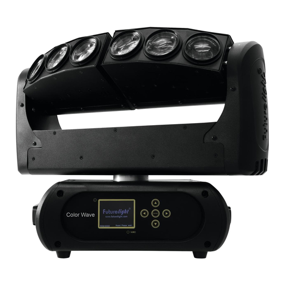
Geräteübersicht (1) Projektorarm (2) Linse/LED (3) LED-Leiste (4) Projektorkopf (5) Base (6) Gummifuß (7) Control Board (8) LCD-Anzeige (9) Mikrofon (10) Pfeil-Taste nach links (11) Pfeil-Taste nach unten (12) Enter-Taste (13) Pfeil-Taste nach rechts (14) Pfeil-Taste nach oben (15) Tragegriff (16) Gehäuseschraube (17) 5-poliger DMX-Eingang (18) 3-poliger DMX-Eingang... -
Seite 9: Installation
INSTALLATION Projektormontage Die Aufhängevorrichtungen des Projektors muss so gebaut und bemessen sein, dass sie 1 Stunde lang ohne dauernde schädliche Deformierung das 10-fache der Nutzlast aushalten kann. Die Installation muss immer mit einer zweiten, unabhängigen Aufhängung, z. B. einem geeigneten Fangnetz, erfolgen. - Seite 10 Die Projektorbase lässt sich auf zwei verschiedene Arten montieren. Das Gerät kann direkt auf den Boden gestellt werden oder in jeder möglichen Position im Trussing installiert werden, ohne seine funktionellen Eigenschaften zu verändern. Beachten Sie bitte bei der vertikalen Installation im Trussing, dass der Omega-Halter immer parallel zum Trussing verläuft.
-
Seite 11: Anschluss An Den Dmx-512 Controller / Verbindung Projektor - Projektor
Anschluss an den DMX-512 Controller / Verbindung Projektor – Projektor Achten Sie darauf, dass die Adern der Datenleitung an keiner Stelle miteinander in Kontakt treten. Die Geräte werden ansonsten nicht bzw. nicht korrekt funktionieren. Beachten Sie, dass die Startadresse abhängig vom verwendeten Controller ist. Unbedingt Bedienungsanleitung des verwendeten Controllers beachten. -
Seite 12: Anschluss Ans Netz
Betrieb auf. Während des Reset justieren sich die Motoren aus und das Gerät ist danach betriebsbereit. Stand Alone-Betrieb Die COLOR WAVE lässt sich im Stand Alone-Betrieb ohne Controller einsetzen. Trennen Sie dazu die COLOR WAVE vom Controller und rufen Sie das vorprogrammierte Programm auf. Bitte beachten Sie weitere Hinweise unter Control Board. -
Seite 13: Dmx-Gesteuerter Betrieb
Steuerkanäle 22 bis 42. Bitte vergewissern Sie sich, dass sich die Steuerkanäle nicht mit anderen Geräten überlappen, damit die COLOR WAVE korrekt und unabhängig von anderen Geräten in der DMX-Kette funktioniert. Werden mehrere COLOR WAVEs auf eine Adresse definiert, arbeiten sie synchron. -
Seite 14: Dmx-Protokoll
DMX-Protokoll Mode/Channel Decimal Hexad. Percentage Eigenschaft St. Ex. Horizontale Bewegung (PAN) Wenn Sie den Regler verschieben, bewegen Sie den Kopf horizontal (PAN). Allmähliches Einstellen des 0% 100% F Kopfes bei langsamen Schieben des Reglers (0-255, 128-Mitte). Der Kopf kann an jeder gewünschten Einstellung angehalten werden. - Seite 15 DF 13% 87% F Strobe-Effekt mit zunehmender Geschwindigkeit 224 255 E0 FF 88% 100% S Offen Öffnender Puls-Effekt S Geschlossen DF 13% 87% F Strobe-Effekt mit zunehmender Geschwindigkeit 224 255 E0 FF 88% 100% S Offen Schließender Puls-Effekt S Geschlossen DF 13% 87% F Strobe-Effekt mit zunehmender Geschwindigkeit 224 255 E0...
- Seite 16 Rainboweffekt rückwärts 0% 100% F Mit zunehmender Geschwindigkeit Farbwechsel linear & Schneller Farbsprung S Schwarz F Rot 100% / Grün zunehmend / Blau 0% / Weiß 0% 3F 13% 25% F Rot abnehmend / Grün 100% / Blau 0% / Weiß 0% 5D 25% 36% F Rot 0% / Grün 100% / Blau zunehmend / Weiß...
- Seite 17 244 245 F5 96% 96% S Rot 246 247 F7 96% 97% S Grün 248 249 F9 97% 98% S Blau 250 251 FA FB 98% 98% S Weiß 252 255 FC FF 99% 100% S Alle Farben LED 2 - Farbvoreinstellungen S Schwarz F Rot 100% / Grün zunehmend / Blau 0% / Weiß...
- Seite 18 214 243 D6 F3 84% 95% F Rot 100% / Grün 0% / Blau 0% / Weiß abnehmend 244 245 F5 96% 96% S Rot 246 247 F7 96% 97% S Grün 248 249 F9 97% 98% S Blau 250 251 FA FB 98% 98% S Weiß...
-
Seite 19: Control Board
Control Board Das Control Board bietet mehrere Möglichkeiten: so lassen sich z. B. die DMX-Startadresse eingeben, das vorprogrammierte Programm abspielen oder ein Reset durchführen. Drücken Sie die Enter-Taste, so dass sich das Display einschaltet. Durch Drücken der geeigneten Pfeil- Taste (nach unten, nach oben, nach links und nach rechts) können Sie sich im Hauptmenü bewegen. Zur Auswahl des gewünschten Menüpunktes drücken Sie die Enter-Taste. -
Seite 20: Connect
Standard Extended Benutzerdefinierte User Mode Basic-8bit Kanalreihenfolge Basic-16bit Users User Max Channel = XX Preset-Benutzerd. Edit User PAN = CH01 ... Effektradjustierung; --Password-- Password=XXX Calibration Standardposition Color ... Color =XXX ... Passwort „050“ Name Name --Password-- Passwort „050“ Fixture ID ... -
Seite 21: Information
Information Time information Betriebsstunden Gerät seit dem Einschalten (current) Mit dieser Funktion lassen sich die temporären Betriebsstunden des Gerätes seit dem Einschalten auslesen. Auf dem Display erscheint “XXXX”, “X“ steht für die Anzahl der Stunden. Der Zähler wird beim Abschalten auf 0 zurückgesetzt. - Seite 22 UI Set Mikrofonempfindlichkeit Mit dieser Funktion lässt sich die Mikrofonempfindlichkeit zwischen 0 % und 99 % einstellen. • Wählen Sie “Mic Sens” durch Drücken der Up/Down-Tasten. • Drücken Sie die Up/Down-Taste, um die gewünschte Empfindlichkeit einzustellen. • Drücken Sie die Enter-Taste zur Bestätigung. Auto-Modus wenn kein DMX Mit der Funktion "No Signal“...
-
Seite 23: Program
Calibration Effektradjustierung Mit dieser Funktion lassen sich die Effekträder auf die korrekten Ausgangspositionen kalibrieren. Das Passwort für diese Funktion ist „050“. Fixture ID Mit dieser Funktion können Sie diverse Menüpunkte per RDM abrufen. Das Gerät unterstützt RDM. Die Abkürzung RDM steht für "Remote Device Management" und macht eine Fernabfrage bzw. - Seite 24 Szenen automatisch aufzeichnen Das Gerät verfügt über einen internen DMX-Recorder, mit dem sich programmierte Szenen aus dem DMX- Controller auf das Gerät übertragen lassen. Stellen Sie die gewünschten Szenen-Nummern über die Up/Down-Tasten ein (von – bis). Wenn Sie nun die Szenen auf Ihrem Controller aufrufen, werden diese automatisch auf das Gerät übertragen.
-
Seite 25: Fehlermeldungen
Beispiel: Programm 2 enthält die Szenen: 10, 11, 12, 13; Programm 4 enthält die Szenen: 8, 9, 10 und Programm 6 enthält die Szenen: 12, 13, 14, 15, 16 Chase Part 1 ist Programm 2; Chase Part 2 ist Programm 3; Chase Part 3 ist Programm 6 Die 3 Slave-Gruppen durchlaufen das Auto Programm in bestimmten Zeitabschnitten, wie die folgende Abbildung zeigt:... -
Seite 26: Sicherungswechsel
Dabei muss unter anderem auf folgende Punkte besonders geachtet werden: 1) Alle Schrauben, mit denen das Gerät oder Geräteteile montiert sind, müssen fest sitzen und dürfen nicht korrodiert sein. 2) An Gehäuse, Befestigungen und Montageort (Decke, Abhängung, Traverse) dürfen keine Verformungen sichtbar sein. -
Seite 27: Technische Daten
TECHNISCHE DATEN Spannungsversorgung: 100-240 V AC, 50/60 Hz ~ Gesamtanschlusswert: 120 W DMX-Steuerkanäle: 17/18/20/21 DMX512-Anschluss: 5-pol. und 3-pol. XLR Musiksteuerung: über eingebautes Mikrofon Blitzrate: 20 Hz LED-Typ: 10-W-QCL Anzahl der LEDs: Max. Schwenkbewegung (PAN): 630° Max. Kippbewegung (TILT): 240° Abstrahlwinkel: 2,5°...