Herunterladen Inhalt Inhalt Diese Seite drucken
Inhaltsverzeichnis

Werbung

Verfügbare Sprachen

Verfügbare Sprachen

MIXING CONSOLE
Owner's Manual
Mode d'emploi
Bedienungsanleitung
M

Werbung

Inhaltsverzeichnis
loading

Inhaltszusammenfassung für Yamaha M2500

  • Seite 1 MIXING CONSOLE Owner’s Manual Mode d’emploi Bedienungsanleitung...
  • Seite 2 300 ohm ribbon lead, change the lead-in to coaxial type cable. If these corrective measures do not produce satisfactory results, please contact the local retailer authorized to distribute this type of product. If you can not locate the appropriate retailer, please contact Yamaha Corporation of America, Electronic Service Division, 6600 Orangethorpe Ave, Buena Park, CA 90620 The above statements apply ONLY to those products distributed by Yamaha Corporation of America or its subsidiaries.
  • Seite 3: Operating Notes

    Important Information Read the Following Before Operating M2500 Warnings Cautions • Do not allow water to enter this unit or allow the • This unit is heavy. Use two or more people to unit to become wet. Fire or electrical shock may carry it.
  • Seite 4: Inhaltsverzeichnis

    Introduction Thank you for purchasing the Yamaha M2500 mixing console. The M2500 is a highly cost- effective mixing console that features functionality such as scene memory, PAN control that is switchable between LR/LCR, and GROUP/AUX FADER FLIP switches. In order to take full advantage of the M2500’s functionality and ensure trouble-free use, please read...
  • Seite 5: Features Of The System

    Scenes can be recalled at any time from the front of 25 output buses. The M2500 is ideal for a panel or via MIDI. In addition, control change wide range of applications from use as a main messages can be used to individually switch PA mixer to use in installed systems.
  • Seite 6: Control Panel

    ), phantom power is on. At this time Monaural input channels the indicator above the switch will light. The M2500-24 {32/40C/48C/56C} provides 24 {32/ Note: If you wish to use phantom power, make 40/48/56} input channels. The specifications of each...
  • Seite 7 STEREO bus and the els sent to GROUP buses 1–8 as shown in the MONO/C bus. following diagram. < Response curve 3 > 1-2/3-4/5-6/7-8 switches= on Signal sent to GROUP buses 1/3/5/7 Signal sent to GROUP buses 2/4/6/8 EVEN PAN control M2500—Owner’s Manual...
  • Seite 8 M PEAK/NOM/SIGNAL indicators The function of this switch and these indicators will These three indicators allow you to check the pre- change depending on the mode of the M2500. fader signal level of the monaural input channel. • PEAK indicator...
  • Seite 9 Control panel Stereo input channels The M2500 provides four stereo input channels, allowing line-level stereo sources such as sub-mixers, effect processors, and CD players to be input. Of the stereo input channels 1–4, channel 1 provides both XLR and RCA phono input jacks, and you can select GAIN and use one of these.
  • Seite 10 The function of this switch and these indicators will pressed in ( ), the equalizer is on. change depending on the mode of the M2500. F AUX 1–AUX 14 controls In normal mode These adjust the level at which the signal of the stereo...
  • Seite 11 ON/EDIT AUX3 from CPU AUX4 AUX5 AUX6 AUX 7-10 Same as AUX 3-6 AUX 11-14 Same as AUX 3-6 L/MONO 2 stage EQ ST CH 2-4 ST CH 2-4 Same as ST CH 1 INPUT 2 stage EQ M2500—Owner’s Manual...
  • Seite 12: Group/Aux Master Section

    MONITOR MASTER PFL/AFL buses and can be monitored from the MONITOR OUT L/R and the PHONES jacks. MONITOR INPUT MASTER (PFL) INSERT I/O AUX 1 to METER AUX OUT +4dB AUX 2-6 Same as AUX 1 M2500—Owner’s Manual...
  • Seite 13 GROUP/AUX FLIP switch= AUX ( The signals of GROUP buses 1–8 will be sent to chan- nels A7/G1–A14/G8 respectively, and output individ- ually from the AUX/GRP OUT A7/G1–A14/G8 jacks. LEVEL LEVEL A7 / G1 A8 / G2 EVEN MONO M2500—Owner’s Manual...
  • Seite 14 The signals of GROUP buses 1–8 will be sent to chan- MONO MONO nels G1/A7–G8/A14 respectively, and will be output individually from the GRP/AUX OUT G1/A7–G8/ A14 jacks. CHECK CHECK ON/EDIT ON/EDIT EVEN G1 / A7 G2 / A8 MONO M2500—Owner’s Manual...
  • Seite 15 G1/A7–G8/A14 section will be sent to the ST bus. If the MONO switch is on, the signal of the G1/A7–G8/A14 section will be sent directly to the MONO/C bus. (Refer to response curve diagram 2 on page 4.) M2500—Owner’s Manual...
  • Seite 16 G Fader The function of this switch and these indicators will This adjusts the output level of the GRP/AUX OUT. change depending on the mode of the M2500. H AFL (after fader listen) switch In normal mode This switch allows you to monitor the signal of the You can use the ON/EDIT switch to turn each G1/ G1/A7–G8/A14 section from the MONITOR OUT/...
  • Seite 17: Group/Aux Flip Switch

    STEREO bus GROUP buses 1–8 can be used as group buses. This set- MONO/C bus ting is more convenient when you are using the M2500 MATRIX bus as a main console, since you will be able to use the 100 mm faders to control the group buses.
  • Seite 18 AUX buses 7–14 Master control Rotary faders 100 mm faders 100 mm faders Channel assign switch (MATRIX/ST/MONO/LCR) PAN control Mute switch ON/EDIT INSERT I/O Note: The output channels of AUX buses 1–6 are not affected by the GROUP/AUX FLIP switch. M2500—Owner’s Manual...
  • Seite 19: Stereo/Monaural Master Section

    F ON/EDIT switch / ON, CHECK indicators The function of this switch and these indicators will STEREO MONO/C change depending on the mode of the M2500. In normal mode You can use the ON/EDIT switch to turn MONO/C STEREO section OUT on/off.
  • Seite 20 INSERT I/O ST L ST OUT +4dB CHECK Control ON/EDIT from CPU MATRIX INSERT I/O ST R ST OUT +4dB INSERT I/O MONO/C +4dB MONO/C CHECK MATRIX Control ON/EDIT from CPU MONITOR LEVEL +4dB MASTER MONO/C INPUT MASTER PHONES M2500—Owner’s Manual...
  • Seite 21: Matrix Section

    (page 11) are on, these controls adjust the level of the signal that is sent from the corresponding The M2500 provides an eight channel matrix section GRP/AUX OUT to the matrix. The “ ” position is that allows the output signals from the G1/A7–G8/ nominal level.
  • Seite 22: Monitor Section

    The PHONES jack will monitor the ST OUT (L/R) jacks. If this switch is off ( ), the MONITOR MAS- output signal. TER AFL signals (after-fader signals of priority order 2) can be monitored from the MONITOR OUT/ PHONES jacks. M2500—Owner’s Manual...
  • Seite 23 INSERT I/O ST L ST OUT +4dB CHECK Control ON/EDIT from CPU MATRIX INSERT I/O ST R ST OUT +4dB INSERT I/O MONO/C +4dB MONO/C CHECK MATRIX Control ON/EDIT from CPU MONITOR LEVEL +4dB MASTER MONO/C INPUT MASTER PHONES M2500—Owner’s Manual...
  • Seite 24: Talkback/Oscillator Section

    This adjusts the level of the talkback or oscillator. E ON switch This is an on/off switch for the talkback. If this is on, the indicator above the switch will light. If you wish to use the oscillator, you must turn off this switch. M2500—Owner’s Manual...
  • Seite 25: Meter Select Section

    Meter select section Control section In this section you can select the source whose level The M2500 is able to save “scenes“ that contain the will be displayed by the meter bridge section. Only on/off status for each monaural/stereo input channel, one of the sources 1–4 can be selected.
  • Seite 26 “ ,” indicating that the M2500 is ready to store the scene. If you press the Note: Be aware that in Check mode, pressing a STORE switch once again, the scene will be stored. If...
  • Seite 27: Meter Bridge

    The MONO/C level meter will not function. panel DC POWER INPUT connector (page 29) to This meter has a PEAK indicator that lights 3 dB the M2500 mixer. before peak level. C PHANTOM MASTER indicator This will light when the rear panel PHANTOM MAS- TER switch (page 29) is on.
  • Seite 28: Rear Panel

    0 dB. The pin wiring is as follows. Tip (send) 1/4" phone plug Tip (send) Ring (return) To processor’s input Sleeve (ground) 1/4" TRS phone plug Tip (return) Sleeve (ground) 1/4" phone plug Connect to INSERT I/O jack From processor’s output Sleeve (ground) M2500—Owner’s Manual...
  • Seite 29: Stereo Input Channel Input/Output Jacks

    –20 dB. In order to use these jacks, you must set the A/B select switch of stereo input channel 1 to the B position. The pin wiring is as follows. RCA phono plug Tip (send) Sleeve (ground) M2500—Owner’s Manual...
  • Seite 30: Master Section Input/Output Jacks

    +4 dB. The pin wiring is as follows. G1/A7–G8/A14 section. Nominal output level is +4 dB. The pin wiring is as follows. 2 (hot) Female XLR plug 3 (cold) 2 (hot) Female XLR plug 3 (cold) 1 (ground) 1 (ground) M2500—Owner’s Manual...
  • Seite 31 These are 1/4" phone jacks (unbalanced) for mixing a line level signal from an external device into the STE- REO bus L/R and MONO/C bus respectively. Nomi- nal input level is +4 dB. The pin wiring is as follows. Tip (send) 1/4" phone plug Sleeve (ground) M2500—Owner’s Manual...
  • Seite 32 In this case, each PW3000MA connecting these to a sequencer or to the MIDI inter- will supply 50% of the power to the M2500. In the face of a computer, scenes can be selected from an unlikely event that one of the PW3000MA units fail, external device, or scene memories can be backed up.
  • Seite 33: The Scene Memory Function

    This is the normal operating mode in which scenes connector can also recall scenes, and when a scene is are recalled and stored. When the M2500 is in Nor- recalled, a corresponding program change message mal mode, the indicators of the CHECK switch and can be transmitted from the MIDI OUT connector.
  • Seite 34: Operation In Normal Mode

    0–9/ENTER switches. Storing a scene 2. Press the RECALL switch. 1. With the M2500 in Normal mode, use the ON/ EDIT switches of the monaural/stereo input RECALL channels, the G1/A7–G8/A14 section, the STE- REO section, and the MONO/C section to make The scene of the selected scene memory number will the desired on/off settings.
  • Seite 35: Check Mode Operation

    MONO/C section. This allows you to check the on/ stored. (With the factory settings, this is turned off settings of the selected scene before you actually off.) To turn memory protect off, refer to page 34. recall it. M2500—Owner’s Manual...
  • Seite 36 The scene whose on/off settings you checked will be 3. Use the ON/EDIT switches of each monaural/ recalled, and the M2500 will automatically return to Nor- stereo input channel, the G1/A7–G8/A14 sec- mal mode. If you wish to return to Normal mode without tion, the STEREO section, and the MONO/C recalling the scene, press the CHECK switch once again.
  • Seite 37: Utility Mode Procedures

    Note: If a MIDI program change is received while • If “ ” is selected in Utility mode, the M2500 will return to Normal All scene memories (1–128) will be erased. mode. • If “ ”–“ ” is selected The scene memory of the corresponding number (1–...
  • Seite 38 Control change messages will not be transmitted or via its MIDI IN/OUT connectors, the scene memory received. contents of the other M2500 will be copied to the first M2500. Specify the value and press the STORE key to • If “...
  • Seite 39: Control Change Table

    “on.” Also, when you press an The following table shows the M2500 channels (and ON/EDIT switch on the M2500 to turn it on/off, the mute groups) that correspond to each control change corresponding control change number will be trans- number.
  • Seite 40: Mute Groups

    Switch to the on/off settings of memory number 3 CHECK CHECK CHECK CHECK CHECK The mute settings of memory number 1 are cancelled ON/EDIT ON/EDIT ON/EDIT ON/EDIT ON/EDIT CHECK CHECK CHECK CHECK CHECK ON/EDIT ON/EDIT ON/EDIT ON/EDIT ON/EDIT MUTE MUTE M2500—Owner’s Manual...
  • Seite 41: About The Local Control Circuit

    (off) settings of the channels that you wish to use as a mute group. In the unlikely event that the system of the M2500 2. Press the UTILITY switch to move to Utility experiences a malfunction so that the scene memory...
  • Seite 42: Error Messages

    Error messages While the M2500 is being operated or when the power is turned on, the MEMORY display may show one of the following error messages. If this occurs, refer to the corresponding explanation and take appropriate action. An error occurred while receiving MIDI The voltage of the internal battery has data.
  • Seite 43: Specifications

    20 kHz filter with infinite dB/octave attenuation. +15, –15 dB maximum HIGH 10 kHz (shelving) For European Model HIGH-MID 400– 8 kHz (peaking) Purchaser/User information specified in EN55103-1 and EN55103-2. LOW-MID 80–1.6 kHz (peaking) Conformed Enviroment: E1, E2, E3 and E4. 100 Hz (shelving) M2500—Owner’s Manual...
  • Seite 44: Input/Output Characteristics

    20 mW 100 Ω PHONES OUT [L, R] Stereo Phone Jack 40 Ω Phones 30 mW 75 mW *1 0 dB=0.775 Vrms. *2 Balanced. *3 Unbalanced (T=OUTPUT, R=INPUT, S=GND). *4 Unbalanced. *5 n=56, 48, 40, 32 or 24 M2500—Owner’s Manual...
  • Seite 45: Other

    Power supply remote +15 V ±15 V GND +48 V GND –15 V +12 V +12 V GND / power supply remote Power supply remote +48 V FRAME GND Included items Power supply connection cable (3 m, 10 pin) M2500—Owner’s Manual...
  • Seite 46: Dimensions

    Dimensions Front Side 1400: M2500-24 1642: M2500-32 1899: M2500-40C 2142: M2500-48C 2385: M2500-56C Rear M2500-24 M2500-32 M2500-40C M2500-48C M2500-56C Units: mm M2500—Owner’s Manual...
  • Seite 47: Midi Data Format

    2. MIDI Program Change STATUS 11110000 F0h System Exclusive Message Program change numbers (0–127) correspond to ID No. 01000011 43h Manufacturer's ID No.(YAMAHA) SUB STATUS 0000xxxx 0nh n=0~15(MIDI Channel) scene memory numbers 1–128. This correspondence FORMAT No. 01111110 7Eh Universal Bulk Dump cannot be changed.
  • Seite 48: Midi Implementation Chart

    MIDI Implementation Chart YAMAHA  [MIXING CONSOLE] Date:July/20, 1999 MIDI Implementation Model : M2500 MIDI Implementation Chart Version : 1.0 Chart Function... Transmitted Recognized Remarks Basic Default 1 - 16 1 - 16 Memorized Channel Changed 1 - 16 1 - 16...
  • Seite 49 MIXING CONSOLE Mode d’emploi...
  • Seite 50: Avertissements

    Informations importantes Veuillez lire ce qui suit avant d’utiliser le M2500 Avertissements Précautions • Evitez de mouiller l’appareil ou de laisser péné- • Cet appareil est particulièrement lourd. Il doit trer de l’eau dans son boîtier. Il y a risque être porté...
  • Seite 51 PAN commutable LR/LCR et les commutateurs GROUP/AUX FADER FLIP. Afin de profiter au maximum des possibilités offertes par la M2500 et de garantir un usage sans problèmes, veuillez lire attentivement ce mode d’emploi.
  • Seite 52: Features Of The System

    25 bus de sortie. Vous pouvez rappeler les scènes à tout moment Le M2500 est idéal pour une large palette avec les commandes en face avant ou via MIDI. d’applications allant d’un usage en tant que con- En outre, les messages de commande de contrôle...
  • Seite 53: Panneau De Commandes

    ( ), l’alimentation fan- tôme est disponible. Le témoin situé au-dessus du Le M2500-24 {32/40C/48C/56C} dispose de 24 {32/ commutateur est alors allumé. 40/48/56} canaux d’entrée. Les caractéristiques de chaque canal d’entrée sont identiques pour tous les Remarque: Pour pouvoir utiliser l’alimentation...
  • Seite 54 STEREO et au bus MONO/C. < Courbe de réponse 3 > Comm. 1-2/3-4/5-6/7-8: activés Signal envoyé aux bus GROUP 1/3/5/7 Signal envoyé aux bus GROUP 2/4/6/8 IMP. PAIR Commande PAN M2500— Mode d’emploi...
  • Seite 55 Ces trois témoins permettent de vérifier le niveau du signal du canal d’entrée mono avant curseur. La fonction de ce commutateur et de ces témoins varie selon le mode du M2500. • Témoin PEAK Ce témoin s’allume lorsque le signal excède de 17 dB En mode normal le niveau nominal.
  • Seite 56 Panneau de commandes Canaux d’entrée stéréo Le M2500 dispose de quatre canaux d’entrée stéréo ce qui permet d’y envoyer des signaux venant de sources stéréo de niveau ligne telle que des consoles de mixage secondaires, des processeurs d’effet et des lec- teurs de CD.
  • Seite 57 CHECK enfoncé ( ), l’égaliseur est activé. La fonction de ce commutateur et de ces témoins varie selon le mode du M2500. F Commandes AUX 1–AUX 14 Déterminent le niveau auquel le signal du canal En mode normal d’entrée stéréo (les signaux d’entrée gauche et droit Vous pouvez vous servir du commutateur ON/EDIT sont mixés pour créer un signal mono) est envoyé...
  • Seite 58 AUX3 from CPU AUX4 AUX5 AUX6 AUX 7-10 Same as AUX 3-6 AUX 11-14 Same as AUX 3-6 L/MONO 2 stage EQ ST CH 2-4 ST CH 2-4 Same as ST CH 1 INPUT 2 stage EQ M2500— Mode d’emploi...
  • Seite 59: Section Group/Aux Master

    AUX OUT 1–6 (page 27). Ils passent en outre par les bus MONITOR MASTER PFL/AFL et peuvent être écoutés via les bornes MONITOR OUT L/R et PHO- NES. MONITOR INPUT MASTER (PFL) INSERT I/O AUX 1 to METER AUX OUT +4dB AUX 2-6 Same as AUX 1 M2500— Mode d’emploi...
  • Seite 60 AUX10 GROUP/AUX FLIP = AUX ( Les signaux des bus GROUP 1–8 sont envoyés aux canaux A7/G1–A14/G8 respectivement et acheminés individuellement aux prises AUX/GRP OUT A7/G1– A14/G8. LEVEL LEVEL A7 / G1 A8 / G2 EVEN MONO M2500— Mode d’emploi...
  • Seite 61 MATRIX Les signaux des bus GROUP 1–8 sont envoyés respec- MONO MONO tivement aux canaux G1/A7–G8/A14 et acheminés individuellement aux sorties GRP/AUX OUT G1/ A7–G8/A14. CHECK CHECK ON/EDIT ON/EDIT EVEN G1 / A7 G2 / A8 MONO M2500— Mode d’emploi...
  • Seite 62 Si ST est activé, le signal après PAN de la section G1/A7–G8/A14 est envoyé au bus ST. Si le commutateur MONO est activé, le signal de la section G1/A7–G8/A14 est envoyé directement au bus MONO/C. (Voyez la courbe de réponse 2 à la page 4.) M2500— Mode d’emploi...
  • Seite 63 Règle le niveau de sortie GRP/AUX OUT. La fonction de ce commutateur et de ces témoins H Commutateur AFL (after fader listen) varie selon le mode du M2500. Ce commutateur d’écoute après curseur permet d’écouter le signal de la section G1/A7–G8/A14 via En mode normal les prises MONITOR OUT / PHONES.
  • Seite 64: Group/Aux Flip

    C ainsi qu’aux bus MATRIX. sortie des bus GROUP 1–8 et GROUP/AUX FLIP des bus AUX 7–14. Ce réglage est pratique lorsque vous utilisez le M2500 M2500 comme console “monitor” pour contrôler les Lorsque GROUP ( ) est sélectionné différents niveaux d’écoute sur scène car il permet de Les signaux des bus GROUP 1–8 sont acheminés par la...
  • Seite 65 Curseurs de 100 mm Curseurs de 100 mm Commutateur d’assignation de canal (MATRIX/ST/ MONO/LCR) Commande PAN Commutateur Mute ON/EDIT Boucle d’insertion Remarque: Les canaux de sortie des bus AUX 1–6 ne sont pas affectés par le commutateur GROUP/ AUX FLIP. M2500— Mode d’emploi...
  • Seite 66: Section Master Stéréo/Mono

    (page 18). F Commutateur ON/EDIT / témoins ON, CHECK Section STEREO La fonction de ce commutateur et de ces témoins varie selon le mode du M2500. A Commutateur MATRIX En mode normal Lorsque ce commutateur est activé ( ), le signal Vous pouvez vous servir du commutateur ON/EDIT après curseur ST OUT L/R est envoyé...
  • Seite 67 ST L ST OUT +4dB CHECK Control ON/EDIT from CPU MATRIX INSERT I/O ST R ST OUT +4dB INSERT I/O MONO/C +4dB MONO/C CHECK MATRIX Control ON/EDIT from CPU MONITOR LEVEL +4dB MASTER MONO/C INPUT MASTER PHONES M2500— Mode d’emploi...
  • Seite 68: Matrice

    Matrice MONO/C à la matrice. La position “ ” correspond au niveau nominal. Le M2500 est doté d’une matrice de huit canaux qui D Commandes G1/A7–G8/A14 permet de mixer au niveau souhaité les signaux de Lorsque les commutateurs MATRIX de la section G1/ sortie de la section G1/A7–G8/A14 et de la section...
  • Seite 69: Section Monitor (Écoute)

    MONO/C. coupé ( ), les signaux MONITOR MASTER AFL La prise PHONES produit le signal de sortie ST OUT (des signaux pris après curseur de priorité 2) peuvent (L/R). être écoutés via les prises MONITOR OUT/PHO- NES. M2500— Mode d’emploi...
  • Seite 70 ST L ST OUT +4dB CHECK Control ON/EDIT from CPU MATRIX INSERT I/O ST R ST OUT +4dB INSERT I/O MONO/C +4dB MONO/C CHECK MATRIX Control ON/EDIT from CPU MONITOR LEVEL +4dB MASTER MONO/C INPUT MASTER PHONES M2500— Mode d’emploi...
  • Seite 71: Section Talkback/Oscillator

    50 à 600Ω. D Commande TB/OSC Règle le niveau de l’intercom ou de l’oscillateur. E Commutateur ON Active/coupe l’intercom (Talkback). Le témoin du commutateur choisi s’allume pour indiquer qu’il est activé. Pour utiliser l’oscillateur, coupez l’intercom. M2500— Mode d’emploi...
  • Seite 72: Section Meter Select

    Section Meter Select Section Control Cette section permet de sélectionner le signal dont le Le M2500 peut conserver des “scènes” qui contien- niveau sera affiché sur le tableau de VU-mètres. Vous nent les réglages activé/coupé pour chaque canal avez le choix parmi les sources 1–4.
  • Seite 73 ,” pour signaler que le indique “ ” (No data/pas de données) durant M2500 est prêt à sauvegarder la scène. Si vous environ 2 secondes. appuyez une fois de plus sur le commutateur STORE, la scène est mémorisée. Si vous changez d’avis, Remarque: Si vous appuyez sur un commutateur appuyez sur n’importe quel autre commutateur pour...
  • Seite 74: Tableau Des Vu-Mètres

    +15V/–15V/+12V est correctement fournie via le s’allume 3 dB avant le niveau de la crête. connecteur DC POWER INPUT en face arrière (page 29) à la console de mixage M2500. C Témoin PHANTOM MASTER Ce témoin s’allume lorsque le commutateur d’ali- mentation fantôme PHANTOM MASTER en face...
  • Seite 75: Face Arrière

    Pointe (envoi) Jack 1/4" Pointe (envoi) Anneau (retour) Vers l’entrée du Gaine (masse) Jack TRS 1/4" processeur Pointe (retour) Gaine (masse) Jack 1/4" Dans la prise INSERT I/O De la sortie du processeur Gaine (masse) M2500— Mode d’emploi...
  • Seite 76: Entrées/Sorties Des Canaux D'entrée Stéréo

    1. Le niveau d’entrée nominal va de +10 dB à –20 dB. Pour pou- voir utiliser ces entrées, réglez le commutateur A/B du canal d’entrée stéréo 1 en position B. Voici le câblage. Fiche RCA/Cinch Pointe (envoi) Gaine (masse) M2500— Mode d’emploi...
  • Seite 77: Entrées/Sorties De La Section Master

    +4 dB. Voici le câblage. A14 sont acheminés individuellement. Niveau de sor- tie nominal: +4 dB. Voici le câblage. 2 (chaud) Fiche XLR femelle 3 (froid) 2 (chaud) Fiche XLR femelle 3 (froid) 1 (masse) 1 (masse) M2500— Mode d’emploi...
  • Seite 78 Prises pour jacks 1/4" (asymétriques) permettant de mixer un signal de niveau ligne venant d’un appareil externe dans le bus STEREO L/R et le bus MONO/C respectivement. Niveau d’entrée nominal: +4 dB. Voici le câblage. Pointe (envoi) Jack 1/4" Gaine (masse) M2500— Mode d’emploi...
  • Seite 79 Vous pourriez ainsi relier trois M2500 via MIDI comme illustré ci-dessous. Tout changement de scène DC PARALLEL INPUT DC OUTPUT sur le M2500 maître (1) entraîne un changement de scène similaire sur les M2500 asservis (2/3). MIDI OUT MIDI IN...
  • Seite 80: Mémoires De Scène

    Lorsque le moment. Les messages de changement de pro- M2500 est en mode Normal, les témoins des commu- gramme reçus via MIDI IN permettent aussi de char- tateurs CHECK et UTILITY de la section Control ger des scènes et lorsqu’une scène est chargée, un...
  • Seite 81: Fonctionnement En Mode Normal

    1–8 ne peuvent être sélec- Sauvegarde d’une scène tionnées qu’avec les boutons 0–9/ENTER. 1. Lorsque le M2500 est en mode Normal, servez- 2. Appuyez sur le commutateur RECALL. vous des commutateurs ON/EDIT des canaux d’entrée mono/stéréo et des sections G1/A7–...
  • Seite 82: Fonctionnement En Mode Check

    éteints des canaux d’entrée mono/stéréo, de la section usine, cette protection est coupée). Pour couper la G1/A7–G8/A14, STEREO et MONO/C. Cela vous protection de la mémoire, veuillez voir page 34. permet de vérifier les réglages de la scène avant de la charger. M2500— Mode d’emploi...
  • Seite 83 3. Utilisez les commutateurs ON/EDIT des canaux La scène dont vous venez de vérifier les réglages est d’entrée mono/stéréo ainsi que des sections alors chargée et le M2500 repasse automatiquement G1/A7–G8/A14, STEREO et MONO/C pour en en mode Normal. Si vous souhaitez retourner en modifier l’état activé/coupé.
  • Seite 84: Procédures Du Mode Utility

    La mémoire de scène au numéro correspondant (1– ment de programme arrive lorsque vous êtes en 128) est effacée. mode Utility, le M2500 repasse en mode Normal. Remarque: • Il est impossible de récupérer une scène effacée. • Si la fonction “...
  • Seite 85 M2500 via ses connecteurs MIDI IN/OUT, le contenu • Si “ ”est sélectionné des mémoires de scène de l’autre M2500 est copié Les commandes de contrôle ne sont ni transmises ni dans le premier M2500. Entrez la valeur voulue et reçues.
  • Seite 86: Tableau De Commandes De Contrôle

    64 et 127, ce commutateur Le tableau ci-dessous affiche la correspondance entre est “activé”. Lorsque vous activez/coupez un commu- les canaux du M2500 (ainsi que les groupes Mute) et tateur ON/EDIT sur le M2500, la commande de con- les numéros de commandes de contrôle.
  • Seite 87: Direct Recall

    Les réglages Mute de la scène1 sont annulés Vous passez aux réglages on/off de la scène 3 CHECK CHECK CHECK CHECK CHECK CHECK CHECK CHECK CHECK CHECK ON/EDIT ON/EDIT ON/EDIT ON/EDIT ON/EDIT ON/EDIT ON/EDIT ON/EDIT ON/EDIT ON/EDIT MUTE MUTE M2500— Mode d’emploi...
  • Seite 88: Groupes Mute

    Circuit de contrôle local 1. Sous un numéro de mémoire de scène 1–8, sauvegardez les réglages Mute (off) des canaux Au cas (fort improbable) où le système du M2500 que vous compter utiliser comme groupe Mute connaîtrait une défaillance qui empêcherait le (muet).
  • Seite 89: Messages D'erreur

    Messages d’erreur En cours d’utilisation ou lors de la mise sous tension du M2500, l’affichage MEMORY peut afficher un des messages d’erreur suivants . Dans ce cas, veuillez lire l’explication afin de résoudre le problème. Il y a eu une erreur lors de la réception La tension de la pile interne est tombée...
  • Seite 90: Fiche Technique

    10 kHz (plateau) atténuation infinie dB/octave. HIGH-MID 400– 8 kHz (cloche) LOW-MID 80–1,6 kHz (cloche) Pour le modèle européen 100 Hz (plateau) Informations pour l’acheteur/usager spécifiées dans EN55103-1 et EN55103-2 Environnement adapté: E1, E2, E3 et E4 M2500— Mode d’emploi...
  • Seite 91: Entrées/Sorties

    100 Ω PHONES OUT [L, R] Jack stéréo 40 Ω casque 30 mW 75 mW *1 0 dB=0.775 Vrms. *2 Symétrique. *3 Asymétrique (pointe (T)=sortie, anneau (R)=entrée, S=masse). *4 Asymétrique. *5 n=56, 48, 40, 32 or 24 M2500— Mode d’emploi...
  • Seite 92: Divers

    ±15 V masse +48 V masse –15 V +12 V +12 V masse / Alimentation à distance Alimentation à distance +48 V Masse du cadre Article fourni Câble de connexion du bloc d’alimentation (3 m, 10 broches) M2500— Mode d’emploi...
  • Seite 93: Dimensions

    Dimensions Avant Côté 1400: M2500-24 1642: M2500-32 1899: M2500-40C 2142: M2500-48C 2385: M2500-56C Arrière M2500-24 M2500-32 M2500-40C M2500-48C M2500-56C Unités: mm M2500— Mode d’emploi...
  • Seite 94: Format Des Données Midi

    Les numéros de changement de programme (0–127) STATUS 11110000 F0h System Exclusive Message correspondent aux numéros de mémoires de scène 1– ID No. 01000011 43h Manufacturer's ID No.(YAMAHA) SUB STATUS 0000xxxx 0nh n=0~15(MIDI Channel) 128. Cette correspondance ne peut pas être modifiée. FORMAT No.
  • Seite 95: Midi Implementation Chart

    MIDI Implementation Chart YAMAHA  [MIXING CONSOLE] Date:July/20, 1999 MIDI Implementation Model : M2500 MIDI Implementation Chart Version : 1.0 Chart Function... Transmitted Recognized Remarks Basic Default 1 - 16 1 - 16 Memorized Channel Changed 1 - 16 1 - 16...
  • Seite 96 MIXING CONSOLE Bedienungsanleitung...
  • Seite 97: Wichtige Hinweise

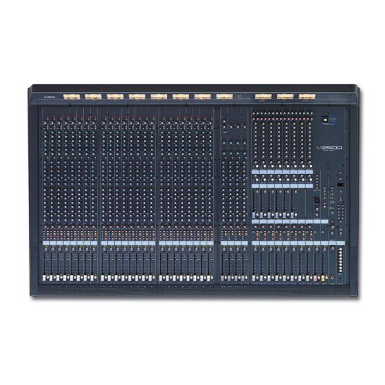
    Wichtige Hinweise Bitte lesen Sie sich folgende Punkte vor der Bedienung des M2500 durch Vorsichtsmaßnahmen Achtung • Vermeiden Sie, daß Wasser oder andere Flüssig- • Dieses Gerät ist besonders schwer. Am besten keiten in das Geräteinnere gelangen. Dann bitten Sie jemanden, Ihnen beim Transport zu besteht nämlich Schlag- oder Brandgefahr.
  • Seite 98 Vorweg Vielen Dank, daß Sie sich für das Mischpult M2500 von Yamaha entschieden haben. Das M2500 ist ein besonders leistungsfähiges Pult für ein kleines Budget mit so praktischen Funktionen wie Szenenspeichern, Panoramaregelung für LR/LCR und einem GROUP/ AUX FADER FLIP-Schalter. Um alle Funktionen Ihres M2500 kennenzulernen und über Jahre hinaus Freude an Ihrem Pult zu haben, sollten Sie sich diese Bedienungsanleitung vollständig durchlesen.
  • Seite 99: Herausragende Merkmale

    über die Bedienoberfläche oder Pulte insgesamt 25 Ausgangsbusse aufweisen. via MIDI wieder aufgerufen werden. Und wem Das M2500 eignet sich für eine Vielzahl von das noch nicht reicht, der kann diese Kanäle mit Anwendungen, darunter die Beschallung (PA) MIDI-Steuerbefehlen (CC) separat ein- und und den Installationseinsatz.
  • Seite 100: Bedienoberfläche

    ), so ist die Mono-Eingangskanäle Phantomspeisung aktiv. Deshalb leuchtet die Diode über dieser Taste. Das M2500-24 {32/40C/48C/56C} bietet 24 {32/40/ 48/56} Eingangskanäle. Die technischen Daten dieser Achtung: Die Phantomspeisung ist nur belegt, Module sind für alle Pultausführungen dieselben. wenn der PHANTOM MASTER-Schalter (Seite 29) eingeschaltet ist.
  • Seite 101: Wenn Die St-Taste Gedrückt Ist

    Diode, und das Post-Pan-Signal dieses Mono-Kanals men 1~8 folgendermaßen: liegt sowohl an der STEREO- als auch an der < Ansprache 3 > MONO/C-Summe an. 1-2/3-4/5-6/7-8 Tasten= an Signale für die GROUP-Summen 1/3/5/7 Signale für die GROUP-Summen 2/4/6/8 EVEN ungeradz. geradz. PAN-Regler M2500—Bedienungsanleitung...
  • Seite 102 Die Funktion dieser Taste und der beiden Dioden Diese drei Dioden zeigen die wichtigsten Pre-Fader- richtet sich nach der gewählten Betriebsart des Pegelwerte eines Mono-Eingangskanals an: M2500. • PEAK-Diode Leuchtet, wenn der Signalpegel 17dB über dem Im Normalbetrieb Nennwert liegt.
  • Seite 103: Stereo-Eingangskanäle

    Bedienoberfläche Stereo-Eingangskanäle Das M2500 bietet vier Stereo-Eingangskanäle, an die Sie Stereo-Signale mit Line-Pegel, die Ausgänge eines Submixers, eines CD-Spielers usw. anschließen kön- nen. Stereo-Kanal 1 der 1~4-Module bietet sowohl XLR- als auch RCA/Cinch-Anschlüsse. Die Module GAIN 2~4 sind mit TRS-Klinkenbuchsen ausgestattet. Des- halb sieht die Bestückung von Modul 1 auch etwas...
  • Seite 104 Wenn die Taste gedrückt ist ( ), so ist die richtet sich nach der gewählten Betriebsart des Entzerrung an. M2500. F AUX 1~AUX 14-Regler Im Normalbetrieb Hier bestimmen Sie den Hinwegpegel der Stereo-Ein- Die ON/EDIT-Taste dient zum Ein- und Ausschalten gangskanäle zu den AUX-Wegen 1~14 (der linke und...
  • Seite 105 Control ON/EDIT AUX3 from CPU AUX4 AUX5 AUX6 AUX 7-10 Same as AUX 3-6 AUX 11-14 Same as AUX 3-6 L/MONO 2 stage EQ ST CH 2-4 ST CH 2-4 Same as ST CH 1 INPUT 2 stage EQ M2500—Bedienungsanleitung...
  • Seite 106: Group/Aux-Mastersektion

    MONITOR MASTER PFL/AFL-Bussen verbun- den und können über die MONITOR OUT L/R- Buchsen und den PHONES-Anschluß abgehört wer- den. MONITOR INPUT MASTER (PFL) INSERT I/O to METER AUX 1 AUX OUT +4dB AUX 2-6 Same as AUX 1 M2500—Bedienungsanleitung...
  • Seite 107 (Pre) oder hinter den LEVEL-Reglern abgreifen. AUX10 GROUP/AUX FLIP-Taste= AUX ( Die Signale der GROUP-Summen 1~8 liegen an den Kanälen A7/G1~A14/G8 an und werden über die Buchsen AUX/GRP OUT A7/G1~A14/G8 separat ausgegeben. LEVEL LEVEL A7 / G1 A8 / G2 EVEN MONO M2500—Bedienungsanleitung...
  • Seite 108 GROUP/AUX FLIP-Taste= GROUP ( MATRIX MATRIX MONO MONO Die Signale der GROUP-Busse 1~8 werden an die Kanäle G1/A7~G8/A14 angelegt und folglich separat über die GRP/AUX OUT G1/A7~G8/A14-Buchsen ausgegeben. CHECK CHECK ON/EDIT ON/EDIT EVEN G1 / A7 G2 / A8 MONO M2500—Bedienungsanleitung...
  • Seite 109 • Wenn die LCR-Taste nicht gedrückt ist, fun- gieren ST und MONO als herkömmliche Zuordnungstasten. Ist ST gedrückt, liegt das Post-Pan-Signal der G1/A7~G8/A14-Sektion am ST-Bus an. Ist MONO gedrückt, so wird die G1/A7~G8/A14-Sektion mit der MONO/C- Summe verbunden. (Siehe auch “Ansprache 2” auf Seite 4.) M2500—Bedienungsanleitung...
  • Seite 110: Im Check-Betrieb (Szenen)

    Die Funktion dieser Taste und der beiden Dioden Hiermit stellen Sie den GRP/AUX OUT-Ausgangspe- richtet sich nach der gewählten Betriebsart des gel ein. M2500. H AFL-Taste (After Fader Listen) Im Normalbetrieb Mit dieser Taste können Sie das Signal der G1/A7~...
  • Seite 111: Group/Aux Flip-Taste

    REO-, MONO/C- und MATRIX-Bus angelegt. 8 oder die AUX-Busse 7~14 an GROUP/AUX FLIP die gewünschten Ausgänge Diese Einstellung empfiehlt sich, wenn Sie das M2500 anlegen. als “Monitorpult” verwenden und den Abhörpegel der einzelnen Signale (d.h. die AUX-Busse 1~14) Wenn GROUP gewählt ist ( separat über die 100mm-Fader einstellen möchten.
  • Seite 112 • GROUP/AUX FLIP-Taste= AUX (Hauptzweck: Monitorpult) Ausgangskanal GROUP-Busse 1~8 AUX-Busse 1~6 AUX-Busse 7~14 Master-Regler Drehregler 100 mm-Fader 100 mm-Fader Kanalzuordnungstaste (MATRIX/ST/MONO/LCR) PAN-Regler Stummschaltung ON/EDIT INSERT I/O Achtung: Die Ausgangszuordnung der AUX-Busse 1~6 kann mit der GROUP/AUX FLIP-Taste nicht geändert werden. M2500—Bedienungsanleitung...
  • Seite 113: Stereo/Mono-Mastersektion

    MONO/C-Signal an die Matrix angelegt (Seite 18). F ON/EDIT-Taste / ON-, CHECK-Diode Die Funktion dieser Taste und der beiden Dioden STEREO-Sektion richtet sich nach der gewählten Betriebsart des M2500. A MATRIX-Taste Wenn diese Taste gedrückt ist ( ), wird das Post- Im Normalbetrieb...
  • Seite 114 INSERT I/O ST L ST OUT +4dB CHECK Control ON/EDIT from CPU MATRIX INSERT I/O ST R ST OUT +4dB INSERT I/O MONO/C +4dB MONO/C CHECK MATRIX Control ON/EDIT from CPU MONITOR LEVEL +4dB MASTER MONO/C INPUT MASTER PHONES M2500—Bedienungsanleitung...
  • Seite 115: Matrix-Sektion

    Wenn die MATRIX-Tasten der G1/A7~G8/A14-Sek- tion gedrückt sind (Seite 12), können Sie mit diesen Reglern den Pegel der GRP/AUX OUT-Signale ein- Das M2500 bietet eine Acht-Kanal-Matrix, mit der stellen, die an die Matrix angelegt werden. Die “ ” Sie die Ausgangssignale der G1/A7~G8/A14-Sektion, Position vertritt den Nennpegel.
  • Seite 116: Monitor-Sektion

    (L, R, MONO/C) an den Buchsen MONITOR OUT gedrückt ( ), so liegen die MONITOR MASTER L, R und MONO/C an. AFL-Signale (Post-Fader-Signale der Vorrangsebene Die PHONES-Buchse enthält dann das Signal der ST 2) an den MONITOR OUT/PHONES-Buchsen an. OUT-Buchsen (L/R). M2500—Bedienungsanleitung...
  • Seite 117 INSERT I/O ST L ST OUT +4dB CHECK Control ON/EDIT from CPU MATRIX INSERT I/O ST R ST OUT +4dB INSERT I/O MONO/C +4dB MONO/C CHECK MATRIX Control ON/EDIT from CPU MONITOR LEVEL +4dB MASTER MONO/C INPUT MASTER PHONES M2500—Bedienungsanleitung...
  • Seite 118: Talkback/Oscillator-Sektion

    C MIC-Buchse Hierbei handelt es sich um einen XLR-3-31-Eingang (asymmetrisch), an den Sie ein Kommandomikrofon anschließen können. Verwenden Sie ein Mikrofon mit einer Impedanz von 50~600Ω. D TB/OSC-Regler Hiermit kann die Lautstärke des Kommando- oder Oszillatorsignals eingestellt werden. M2500—Bedienungsanleitung...
  • Seite 119: Meter Select-Sektion

    Bedienoberfläche Meter Select-Sektion Control-Sektion In dieser Sektion können Sie die Signale wählen, Das M2500 bietet sog. “Szenenspeicher”, in denen der deren Pegel in der Meterleiste angezeigt werden. Es An/Aus-Status der Mono- und Stereo-Eingagskanäle, kann nur jeweils eine Signalquelle 1~4 gewählt der G1/A7~G8/A14-, der STEREO- und der MONO/ werden.
  • Seite 120 Sie diese Taste einmal drücken, erscheint die Mel- lang im MEMORY-Display. dung “ ”, um Sie darauf hinzuweisen, daß das M2500 bereit ist zum Speichern. Wenn Sie die Achtung: Wenn Sie sich bei Drücken einer STORE-Taste noch einmal drücken, wird die Szene DIRECT RECALL-Taste gerade im Check-Betrieb gespeichert.
  • Seite 121: Meterleiste

    POWER INPUT-Anschluß auf der Rückseite Dieses Meter ist mit einer PEAK-Diode ausgestattet, (Seite 29) anliegt, leuchtet die betreffende Diode, die etwa 3dB unterhalb der Verzerrungsgrenze zu damit Sie wissen, daß das M2500 mit Strom versorgt leuchten beginnt. wird. C PHANTOM MASTER-Diode Diese Diode leuchtet, wenn sich der PHANTOM MASTER-Schalter auf der Rückseite (Seite 29) in der...
  • Seite 122: Rückseite

    Effektgeräte in den betreffenden Kanal ein- schleifen kann. Der Nennpegel beträgt 0dB. Die Stift- belegung lautet folgendermaßen: Spitze (Hinweg) 1/4"-Klinke Spitze (Hinweg) Ring (Rückweg) Zum Effekteingang Mantel (Masse) 1/4" TRS-Klinke Spitze (Rückweg) Mantel (Masse) 1/4"-Klinke Zur INSERT I/O-Buchse Vom Effektausgang Mantel (Masse) M2500—Bedienungsanleitung...
  • Seite 123: Stereo-Ein- Und Ausgänge

    L- als auch an den R-Kanal ange- Stereo-Eingangskanal 1. Der Nennpegel beträgt legt. +10dB~–20dB. Diese Buchsen sind nur belegt, wenn Sie die A/B-Taste von Eingangskanal auf “B” stellen. Die Stiftbelegung lautet folgendermaßen: RCA-Stecker Spitze (Signal) Mantel (Masse) M2500—Bedienungsanleitung...
  • Seite 124: Ein-/Ausgänge Der Master-Sektion

    Kanäle Signale 1~8. Der Nennausgangspegel beträgt +4dB. G1/A7~G8/A14. Der Nennausgangspegel beträgt Die Stiftbelegung lautet folgendermaßen: +4dB. Die Stiftbelegung lautet folgendermaßen: 2 (heiß) 2 (heiß) Weiblicher XLR-Stecker Weiblicher XLR-Stecker 3 (kalt) 3 (kalt) 1 (Masse) 1 (Masse) M2500—Bedienungsanleitung...
  • Seite 125 Zur INSERT I/O-Buchse Dies sind 1/4"-Klinkenbuchsen (asymmetrisch), über Vom Effektausgang Mantel (Masse) die ein Signal mit Line-Pegel in die STEREO L/R- bzw. MONO/C-Summe eingespeist werden kann. Der Nennpegel beträgt +4dB. Die Stiftbelegung lau- tet folgendermaßen: Spitze (Signal) 1/4"-Klinke Mantel (Masse) M2500—Bedienungsanleitung...
  • Seite 126 An dieser Buchse liegen die über MIDI IN empfange- nen Daten in unveränderter Form wieder an. DC PARALLEL INPUT DC OUTPUT Wenn Sie z.B. drei M2500-Pulte wie folgt miteinan- PW3000MA der verbinden, sorgt das Master-Pult (1) dafür, daß die Slave-Pulte (2/3) im gleichen Moment dieselbe Szene wählen.
  • Seite 127: Die Szenenspeicher

    In dieser Betriebsart können Sie Szenenspeicher ert werden, indem Sie ein externes Gerät mit der sichern und laden. Wenn weder die CHECK- noch MIDI IN-Buchse des M2500 verbinden. Bei Anwahl die UTILITY-Diode leuchtet, befindet sich das eines Szenenspeichers wird auch ein MIDI-Pro- M2500 im Normalbetrieb.
  • Seite 128: Arbeiten Im Normalbetrieb

    • Diese Szenenspeicher 129 und 130 können nur Speichern einer Szene mit den Tasten 0~9/ENTER gewählt werden. 1. Wählen Sie den Normalbetrieb des M2500 und • Wenn Sie mit Mute-Gruppen arbeiten schalten Sie die Mono-/Stereo-Eingangska- (Seite 37), können auch die Szenenspeicher 1~ näle, die G1/A7~G8/A14-, STEREO- und...
  • Seite 129: Arbeiten Im Check-Betrieb

    EDIT-Tasten ändern, ohne daß sich das auf die Signalwiedergabe auswirkt. Kontrollieren einer Szene vor dem Laden (Check) 1. Wenn sich das M2500 im Normalbetrieb befin- det, müssen Sie die CHECK-Taste drücken. ENTER CHECK Die CHECK-Diode leuchtet nun, um anzeugen, daß...
  • Seite 130: Editieren Und Speichern Einer Szene (Check-Betrieb)

    3. Ändern Sie den An/Aus-Status der Kanäle mit Die Szene, deren Einstellungen Sie soeben kontrol- den ON/EDIT-Tasten der Mono-/Stereo-Ein- liert haben, wird geladen und das M2500 wechselt gangskanäle, der G1/A7–G8/A14-, STEREO- wieder in den Normalbetrieb. Wenn Sie den Normal- und der MONO/C-Sektion.
  • Seite 131: Arbeiten Im Utility-Betrieb

    (Speichersicherung) ......on/oFF Die UTILITY-Diode leuchtet nun, um anzuzeigen, (Vorgabe: “ ”) daß sich das M2500 im Utility-Betrieb befindet. Im Mit diesem Parameter können Sie den Inhalt der Sze- MEMORY-Display blinken dann abwechselnd der nenspeicher vor unerwünschten Eingriffen schützen. Name des gerade gewählten Parameters sowie der Ist diese Funktion aktiviert, so können Sie keine Ein-...
  • Seite 132 ” gestellt wurde, werden die Programm- nicht weitergereicht, weil das M2500 hierauf antwor- nummern 0~7 ignoriert.) tet, indem es die Daten sendet. – Wenn Sie auf dem M2500 eine Szene 1~128 aufru- fen, die Daten enthält, wird die entsprechende (Datenblockabwurf) ......ALL/1–128 MIDI-Programmnummer (0~127) zur MIDI Mit diesem Befehl können Sie die Einstellungen aller...
  • Seite 133: Übersicht Der Steuerbefehle

    Steuerbefehlen CC105~ 120 ein- und ausgeschaltet werden. Das System funk- tioniert also genau wie bei den ON/EDIT-Tasten: 0~ Das M2500 kann über seine MIDI IN-Buchse Steuer- 63=aus und 64~127=an. befehle empfangen, mit denen die ON/EDIT-Tasten der Mono/Stereo-Eingangskanäle, der G1/A7–G8/ Achtung: Wenn Sie die Kanäle des M2500 tatsäch-...
  • Seite 134: Arbeiten Mit Mute-Gruppen

    ON/EDIT ON/EDIT ON/EDIT ON/EDIT ON/EDIT ON/EDIT An/Aus-Einstellungen von Szene 3 werden verwendet. Die “AUS”-Einstellungen von Szene 1 werden deaktiviert CHECK CHECK CHECK CHECK CHECK CHECK CHECK CHECK CHECK CHECK ON/EDIT ON/EDIT ON/EDIT ON/EDIT ON/EDIT ON/EDIT ON/EDIT ON/EDIT ON/EDIT ON/EDIT M2500—Bedienungsanleitung...
  • Seite 135: Verwendung Der Mute-Gruppen

    Verwendung der Mute-Gruppen “Local Control”-Schaltung 1. Sichern Sie die benötigten Aus-Einstellungen der Kanäle und Busse in einem Szenenspeicher Wenn die Betriebssoftware des M2500 abstürzt, wer- 1~8. den die ON/EDIT-Tasten der Eingangskanäle und Busse sofort von der Szenenspeicherfunktion abge- 2. Drücken Sie die UTILITY-Taste, um den gleich- koppelt und können dann in Echtzeit bedient wer-...
  • Seite 136: Fehlermeldungen

    Meldung mehrere Sekunden lang ange- Systemfehler (* vertritt die Fehlernum- zeigt. Kontrollieren Sie die MIDI-Verbin- mer) dung und die Einstellungen des Sen- Wenn diese Fehlermeldung erscheint, ders. funktioniert das M2500 nicht erwar- tungsgemäß. Bitten Sie Ihren Yamaha- Händler, das Pult nachzuschauen. M2500—Bedienungsanleitung...
  • Seite 137: Allgemeine Spezifikationen

    CH INPUT-Klangregelung +15, –15 dB max. Für das europäische Modell HIGH 10 kHz (Kuhschwanz) Kunden-/Benutzerinformation nach EN55103-1 und EN55103-2. HIGH-MID 400– 8 kHz (Glocke) Entspricht den Umweltschutzbestimmungen: E1, E2, E3 und E4 LOW-MID 80–1,6 kHz (Glocke) 100 Hz (Kuhschwanz) M2500—Bedienungsanleitung...
  • Seite 138: Ein-/Ausgangsspezifikationen

    10 mW 20 mW Stereo-Klinkenbuchse PHONES OUT [L, R] 100Ω 40Ω Kopfhörer 30 mW 75 mW *1 0 dB= 0,775 Vrms. *2 Symmetrisch. *3 Asymmetrisch (T= Ausgang, R= Eingang, S= Masse). *4 Asymmetrisch. *5 n=56, 48, 40, 32 oder 24 M2500—Bedienungsanleitung...
  • Seite 139: Andere

    Spezifikationen Andere Anschlußbedrahtung Stiftnr. Signalname Stromversorgung +15 V ±15 V GND +48 V GND –15 V +12 V +12 V GND / Stromversorgung Stromversorgung +48 V FRAME GND (Chassis-Masse) Lieferumfang Stromkabel (3m, 10 Stifte) M2500—Bedienungsanleitung...
  • Seite 140: Abmessungen

    Abmessungen Vorne Seite 1400: M2500-24 1642: M2500-32 1899: M2500-40C 2142: M2500-48C 2385: M2500-56C Hinten M2500-24 M2500-32 M2500-40C M2500-48C M2500-56C Einheit: mm M2500—Bedienungsanleitung...
  • Seite 141: Midi-Datenformat

    = MUTE GROUP (1~8) 4. MIDI-Echofunktion Die MIDI Echo-Funktion kann auf [on/oFF] gestellt werden. Wenn der MIDI-Puffer infolge einer zu gro- ßen Datenmenge überläuft, wird die Echo-Funktion deaktiviert. Anschließend überträgt die MIDI OUT- Buchse nur noch die internen Daten des M2500. M2500—Bedienungsanleitung...
  • Seite 142: Midi Implementation Chart

    MIDI Implementation Chart YAMAHA  [MIXING CONSOLE] Date:July/20, 1999 MIDI Implementation Model : M2500 MIDI Implementation Chart Version : 1.0 Chart Function... Transmitted Recognized Remarks Basic Default 1 - 16 1 - 16 Memorized Channel Changed 1 - 16 1 - 16...
  • Seite 143 YAMAHA CORPORATION V443030 R0 1 IP 148 Pro Audio Division, #18/3 P.O. Box 3, Hamamatsu, 430-8651, Japan NP Printed in Taiwan...

Inhaltsverzeichnis