Inhaltsverzeichnis
Werbung
Verfügbare Sprachen
Verfügbare Sprachen
Quicklinks
Werbung
Kapitel
Inhaltsverzeichnis
Fehlerbehebung

Verwandte Anleitungen für Klarstein 10031084


Inhaltszusammenfassung für Klarstein 10031084
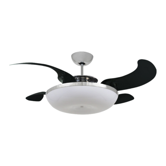
- Seite 1 Deckenventilator 10031084...
-
Seite 2: Inhaltsverzeichnis
Fehlersuche und Fehlerbehebung 10 Hinweise zur Entsorgung 10 Konformitätserklärung 10 Technische Daten Artikelnummer 10031084 Stromversorgung 220-240 V ~ 50-60 Hz Sicherheitshinweise • Lassen Sie die Installation von einem ausgebildeten Elektriker durchführen. • Stellen Sie vor der Installation den Strom am Sicherungskasten ab. -
Seite 3: Geräteübersicht Und Zubehör
Geräteübersicht und Zubehör Geräteteile Fernbedienung Zubehörteile A Halterung a Fernbedienung h Spannschrauben für die Halterung 2x B Aufhängestange b Fernbedienungs-Abdeckung i Schrauben für die Halterung 2x C Schirm c Receiver j Klammer 1x (optional) D Abdeckung d Fernbedienungs-Wandhalterung k 6 mm Sechskantschlüssel E 40W Ring-Birne e Batterie l 4 mm Sechskantschlüssel... -
Seite 4: Installation
Installation WICHTIG: Bringen Sie den Ventilator nicht an Zwischendecken oder rissigen Decken an. Der Abstand zwischen Ventilator und Boden muss mindestens 2,3 m betragen. Befestigen Sie die Halterung sicher an der Decke. Wählen Sie dazu eine der folgenden beiden Befestigungsmethoden für die Halterung. - Seite 5 Lösen Sie die 2 Schrauben oben am Motor. Schieben Sie den Schirm auf die Aufhängestange. Ziehen Sie die Kabel vom Ventilator durch Abdeckung, Schirm und Aufhängestange. Ziehen Sie nicht zu stark an den Kabeln, um sie nicht zu beschädigen. Schieben Sie die Aufhängestange in die Gabel oben am Motor und drehen Sie sie, bis sich die Löcher decken.
- Seite 6 Einbau einer 2GX13 40W Birne: Nachdem Sie die Abdeckung befestigt haben, nehmen Sie den Lampenschirm ab. Befestigen Sie die Birne und drücken Sie den den Birnenstecker an den Steckplatz, bis die Birne mit einem Klicken einrastet. Schieben Sie die Schraube durch das Loch im Lampenschirm und befestigen Sie sie ihn mit dem 6 mm Sechskantschlüssel.
-
Seite 7: Fernbedienung Und Receiver
Fernbedienung und Receiver Wichtige Hinweise • Achten Sie darauf, dass die Fernbedienung nicht herunterfällt, sie könnte sonst beschädigt werden. • Kürzen Sie nicht das Antennenkabel des Receivers. • Falls Sie die Fernbedienung längere Zeit nicht benutzen, entnehmen Sie die Batterien, damit sie nicht in der Fernbedienung auslaufen können. -
Seite 8: Frequenz-Einstellung
Frequenz-Einstellung 1. Zum Ändern der Einstellung lassen Sich die DIP-Schalter hoch und runter schieben. 2. Receiver und Fernbedienung besitzen beide jeweils vier dieser Schalter, die jeweils gleich eingestellt sein müssen. Es sind insgesamt 16 verschiedene Einstellungen möglich. 3. Die Einstellung beeinflusst die Frequenz des Fernbedienungssignals, über die der Ventilator bedient wird. 4. -
Seite 10: Sicherung Austauschen
Sicherung austauschen Drücken Sie beide Seiten des Sicherungskapsel gegeneinander und drehen Sie sie, um die Kapsel zu öffnen. Entfernen Sie die alte Sicherung aus der Kapsel und ersetzen Sie sie durch eine neue 5A-Sicherung. Zum Verschließen der Kapsel, setzen Sie den Verschluss an die Rillen und drehen Sie ihn wieder fest. -
Seite 11: Technical Data
Troubleshooting 19 Hints on Disposal 19 Declaration of Conformity 19 Technical Data Item number 10031084 Power supply 220-240 V ~ 50-60 Hz Safety Instructions • Installation must be carried out by a qualified electrician. • Turn off the electrical mains at the circuit breaker/fuse box. -
Seite 12: Product Description And Accessory
Product Description and Accessory Equipment Parts Remote Control Accessories Packet A Mounting Bracket a Transmitter h Expansion Screws x2 (Optional) B Downrod Set b Transmitter Cover i Screws For Mounting Bracket x2 C Canopy c Receiver j Clasp x1 (Optional) D Fan Body d Wall bracket For Transmitter k 6mm Hex Wrench... -
Seite 13: Installation
Installation IMPORTANT: Do not install the fan onto the partition ceiling or chapped wall. The ceiling fan must be mounted at a min. height of 7.5 ft/2.3 m of clearance from the floor. The mounting bracket must be securely fastened to a structural ceiling member. - Seite 14 Loosen 2 screws at the yoke of the motor assembly. Slide the canopy into the downrod. Thread the power leads from the fan through the canopy, decorative cover and downrod (take extra care not to pull power wires damage). Set downrod into yoke and rotate until the holes match.
- Seite 15 Plug 2GX13 40W assembly chart: After locking the canopy, remove the lampshade, place the bulb into the lamp holder and insert the T5 bulb plug into the socket, hearing “click” sound, it means the lamp socket are tightened. Let the lamp mounting hole aim at the screw and fix the screw with 6mm Hex wrench.
-
Seite 16: Remote Control And Receiver
Remote Control and Receiver Important Hints • To avoid damaging the transmitter prevents dropping or banging the transmitter. • Do not attempt to shorten the receiver’ s antenna wire. • If the transmitter is not used for some time, please remove batteries to avoid leakage. •... -
Seite 17: Frequency Settings
Frequency Settings 1. These DIP code can be pushed upward and downward to change the setting. 2. Both of these remote control components (receiver and transmitter) have a set of four switches that need to have the same settings. (The total combination becomes 16 frequency codes). 3. -
Seite 19: Fuse Replacement
Fuse Replacement Push both side of the fuse capsule towards each other and twist it to open the fuse capsule. Remove the damaged 5A glass fuse from the capsule then replace a new 5A glass fuse. To close the fuse capsule aline the latch and groove then push in and twist to lock the fuse capsule. -
Seite 20: Datos Técnicos
Detección y resolución de problemas 28 Indicaciones para la retirada del aparato 28 Declaración de conformidad 28 Datos técnicos Número de artículo 10031084 Suministro eléctrico 220-240 V ~ 50-60 Hz Indicaciones de seguridad • Contacte con un electricista cualificado para realizar la instalación. -
Seite 21: Descripción Del Aparato Y Accesorios
Descripción del aparato y accesorios Piezas del aparato Mando a distancia Accesorios A Soporte de montaje a mando a distancia h Tornillo de expansión para soporte x2 B Varilla de extensión b Tapa del mando a distancia i Tornillos para soporte x2 C Cubierta C Receptor j Cierre 1x (opcional) -
Seite 22: Instalación
Instalación IMPORTANTE: No monte el ventilador en un falso techo o en techos agrietados. La distancia entre el ventilador y el suelo debe ser de como mínimo 2,3 Fije el soporte al techo. A continuación, seleccione uno de los siguientes métodos de fijación para el soporte. - Seite 23 Suelte los dos tornillos situados en la parte superior del motor. Desplace la cubierta por la varilla de extensión. Pase el cable del ventilador a través de la cubierta, la cubierta decorativa y la varilla de extensión. No tire demasiado del cable para evitar daños.
- Seite 24 Montaje de una bombilla 2GX13 40W: Después de haber fijado la cubierta, retire la pantalla de la lámpara. Fije la bombilla y presione el conector de la lámpara en el puesto de conexión hasta que la bombilla encaje con un clic.
-
Seite 25: Mando A Distancia Y Receptor
Mando a distancia y receptor Indicaciones importantes • Tenga en cuenta que el mando a distancia no se caiga, podría dañarse. • No acorte el cable de la antena del receptor. • Si no utiliza el mando a distancia durante un periodo de tiempo prolongado, retire la batería para evitar que se provoque una fuga en el mando a distancia. -
Seite 26: Configuración De Frecuencia
Configuración de frecuencia 1. Para modificar los ajustes, levante y baje los interruptores DIP. 2. El receptor y el mando a distancia cuentan con cuatro de estos interruptores que deben ajustarse del mismo modo. En total hay 16 ajustes disponibles. 3. -
Seite 28: Sustituir Fusibles
Sustituir fusibles Presione ambos extremos de la cápsula del fusible la una contra la otra y gírelas para abrir la cápsula. Retire el fusible usado de la cápsula y sustitúyalo por otro fusible nu- evo de 5A. Para cerrar la cápsula, alinee el cierre y la ranura y vuelva a girarlos. Detección y resolución de problemas Problema Posible causa y solución... -
Seite 29: Fiche Technique
Identification et résolution des problèmes 37 Information sur le recyclage 37 Déclaration de conformité 37 Fiche technique Numéro d’ a rticle 10031084 Alimentation électrique 220-240 V ~ 50-60 Hz Consignes de sécurité • Laisser un électricien qualifié effectuer l’installation. • Avant l’installation, couper le courant électrique au niveau de la boîte à fusibles. -
Seite 30: Aperçu De L' A Ppareil Et Accessoires
Aperçu de l’ a ppareil et accessoires Parties de l’appareil Télécommande Accessoires A Support a Télécommande h Vis à poussoir pour le support 2x B Barre d’ a ccroche b Coque de télécommande i Vis pour le support 2x C Cache c Récepteur j Attache 1x (optionnel) D Support... -
Seite 31: Installation
Installation IMPORTANT : ne pas monter le ventilateur sur un faux-plafond ou un plafond fissuré. La distance entre le ventilateur et le sol doit être d’ a u moins 2,3 m. Bien fixer le support au plafond. Pour cela, choisir une des deux méthodes de fixation du support suivantes. - Seite 32 Dévisser les 2 vis sur le dessus du moteur. Recouvrir la barre d’ a ccroche avec la coupole. Faire passer le câble du ventilateur par le cache, la coupole et la barre d’ a ccroche. Ne pas tirer trop fortement sur le câble pour ne pas l’...
- Seite 33 Montage d’une ampoule 2GX13 40 W : Une fois le cache fixé, enlever l’ a bat- jour. Introduire l’ a mpoule et la visser jusqu’ à ce qu’ e lle s’ e ncliquète. Insérer la vis dans le trou de l’ a bat-jour et la visser avec une clé...
-
Seite 34: Télécommande Et Récepteur
Télécommande et récepteur Remarques importantes • Veiller à ne pas laisser tomber la télécommande pour ne pas l’ e ndommager. • Ne pas raccourcir le câble d’ a ntenne du récepteur. • En cas d’inutilisation prolongée de la télécommande, en sortir les piles pour éviter qu’ e lles ne fuient dans la télécommande. -
Seite 35: Réglage De La Fréquence
Réglage de la fréquence 1. Pour modifier le réglage, placer l’interrupteur DIP en position haute ou basse, 2. Le récepteur et la télécommande possèdent chacun 4 interrupteurs qui doivent être réglés à l’identique. En tout, 16 différents réglages sont possibles. 3. -
Seite 37: Remplacer Le Fusible
Remplacer le fusible Appuyer sur les deux côtés de la capsule de sécurité et les faire tour- ner pour ouvrir la capsule. Sortir l’ a ncien fusible de la capsule et le remplacer par un nouveau fusible 5A. Pour verrouiller la capsule, faire coïncider le culot avec les rainures et tourner pour fixer. -
Seite 38: Dati Tecnici
Ricerca e risoluzione dei problemi 46 Smaltimento 46 Dichiarazione di conformità 46 Dati tecnici Articolo numero 10031084 Alimentazione 220-240 V ~ 50-60 Hz Avvertenze di sicurezza • L´installazione deve essere eseguita da un elettricista qualificato. • Prima dell´installazione staccare la corrente tramite l´interruttore o la scatola dei fusibili. -
Seite 39: Descrizione Del Prodotto E Accessori
Descrizione del prodotto e accessori Componenti dispositivo Telecomando Accessori A Staffa di montaggio a Telecomando h Viti a estensione 2x B Asta b Coperchio telecomando i Viti per staffa di montaggio 2x C Calotta c Ricevitore j Morsetto 1x (non incluso) D Coperchio d Supporto a parete per telecomando k Chiave esagonale 6 mm... -
Seite 40: Installazione
Installazione IMPORTANTE: non installare il ventilatore ad un controsoffitto o ad un soffitto con crepe. La distanza tra il ventilatore e il pavimento deve essere almeno di 2,3 m. Fissare saldamente al soffitto la staffa di montaggio. Scegliere uno dei due metodi per il fissaggio. - Seite 41 Svitare le 2 viti sul motore. Inserire la calotta nell´asta. Far passare i cavi del ventilatore attraverso il coperchio, la calotta e l´asta. Non tirare troppo i cavi per non danneggiarli. Fissare l´ asta al motore e ruotarla fino a quando copre i fori.
- Seite 42 Inserire la lampadina 2GX13: Dopo aver fissato il coperchio, rimuovere la calotta. Inserire la lampadina e premere il connettore della lampadina nell´alloggiamento: un clic segnala il corretto inserimento. Inserire la vite attraverso il foro nella calotta e serrare la vite utilizzando la chiave esagonale da 6 mm.
-
Seite 43: Telecomando E Ricevitore43
Telecomando e ricevitore Importanti indicazioni • Non fare cadere il telecomando altrimenti potrebbe danneggiarsi. • Non accorciare il cavo dell´antenna del ricevitore. • In caso di inutilizzo del telecomando, rimuovere le pile. Telecomando e ricevitore Installare prima il ricevitore e inserire poi le pile nel telecomando. Se il telecomando o il ventilatore non funzi- onano correttamente o non funzionano del tutto, provare nel seguente modo: •... -
Seite 44: Impostare La Frequenza
Impostare la frequenza 1. Per modificare l´impostazione, spostare l´interruttore DIP verso l´alto e verso il basso. 2. Il ricevitore e il telecomando possiedono ciascuno quattro interruttori. Sono possibili 16 impostazioni diver- 3. L´impostazione influisce sulla frequenza del segnale del telecomando tramite il quale viene azionato il tele- comando. -
Seite 46: Sostituire Un Fusibile
Sostituire il fusibile Premere entrambi i lati della capsula del fusibile uno contro l´altro e ruotarli per aprire la capsula. Rimuovere il vecchio fusibile dalla capsula e sostituirlo con un nuovo fusibile 5 A. Per chiudere la capsula, allineare la chiusura alle scanalature e avvi- tarla di nuovo.