Grundig UMS 1 Serviceanleitung
Inhaltsverzeichnis
Verfügbare Sprachen
Verfügbare Sprachen
Service
Zusätzlich erforder-
Manual
liche Unterlagen
für den
Komplettservice:
UMS 1
UMS 2
Additionally
required Service
Sach-Nr./Part No.
Manuals for the
72010-748.20
Complete Service:
UMS 1
UMS 2
IR-Geber / IR Remote Control RC-UMS
Änderungen vorbehalten
Subject to alteration
SERVICE MANUAL
Service
Manual
Sicherheit
Safety
Sach-Nr./Part No.
72010-800.00
38
(9.79401-8151 / G.LF 1251)
(9.79402-8151 / G.LF 1351)
(75954-029.64)
Printed in Germany
VK 231 0196
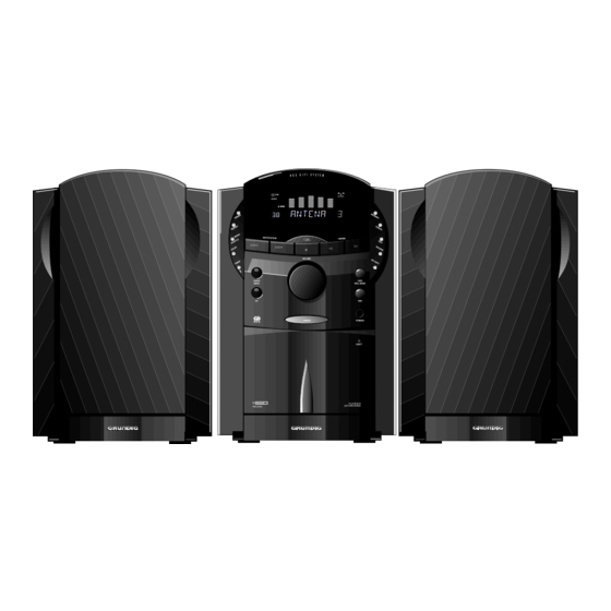
HiFi-Micro-System UMS 1
HiFi-Micro-System UMS 2
3
ANTENA
SLEEP
TUNER
PTY
< STATION >
CD
TAPE
AUX
+
EQUALIZER
VOLUME
R C U M S
Service Manual Sach-Nr.
Service Manual Part No.
72010-748.20
Inhaltsverzeichnis

Verwandte Anleitungen für Grundig UMS 1


Inhaltszusammenfassung für Grundig UMS 1
- Seite 1 Sicherheit UMS 1 UMS 2 Safety Additionally required Service Sach-Nr./Part No. Sach-Nr./Part No. Manuals for the 72010-748.20 72010-800.00 HiFi-Micro-System UMS 1 Complete Service: HiFi-Micro-System UMS 2 ANTENA SLEEP TUNER < STATION > TAPE EQUALIZER VOLUME R C U M S UMS 1 (9.79401-8151 / G.LF 1251)
-
Seite 2: Inhaltsverzeichnis
Testcassette 448 A part no. 35079-023.00 Drehmomentcassette 456 Sach-Nr. 35079-014.00 Cassette torque meter 456 part no. 35079-014.00 Beachten Sie bitte das GRUNDIG Meßtechnik-Programm, das Sie Please note the Grundig Catalog “Test and Measuring Equipment” unter folgender Adresse erhalten: obtainable from: GRUNDIG electronics GmbH GRUNDIG electronics GmbH Würzburger Str. -
Seite 3: Technische Daten, Servicehinweise
UMS 1 / UMS 2 Allgemeiner Teil / General Section Technische Daten Technical Data Verstärker Amplifier Ausgangsleistung (DIN 45500) Output power (DIN 45500) UMS 1 UMS 1 Musikleistung (4Ω) ............. 2 x 24W Music (4Ω) ..............2 x 24W Sinusleistung (4Ω, 10% Klirrfaktor, f = 1kHz) .... 2 x 15W Nominal (4Ω, 10% dist., f = 1kHz) ...... -
Seite 4: Bedienhinweise
Bedienhinweise Hinweis: Dieses Kapitel enthält Auszüge aus der Bedienungsanleitung. Weitergehende Informationen entnehmen Sie bitte der gerätespezifischen Bedienungsanleitung, deren Sachnummer Sie in der entsprechenden Ersatzteilliste finden. Bedienungselemente Fernbedienung POWER Mit dieser Taste wird das Gerät ein- oder SOUND Mit dieser Taste schalten Sie der Reihe nach ALLGEMEINES auf Bereitschaft geschaltet. - Seite 5 Verstärker Radio Ein- und Ausschalten Lautstärke TUNER Speichern von Stationen Wenn Sie den Netzstecker in die Steckdose stecken, schaltet Sie regulierenen die Lautstärke mit dem Einsteller VOLUME. • Drücken Sie TUNER/BAND am Gerät oder eine der Tasten Sie können bis zu 49 Stationen speichern. das Gerät in Bereitschaft.
- Seite 6 Radio Radio RDS Radio Data System (nur UMS 2) Sendernamen vergeben Programmart-Kennung (PTY) (auf der Fernbedienung) Ihr Gerät ist in der Lage, RDS-Informationen, die mit dem Empfangen Sie Sender, die den RDS-Code nicht ausstrahlen, Sendersignal ausgestrahlt werden, zu empfangen und können Sie jeder Station einen Namen Ihrer Wahl geben.
- Seite 7 Allgemeines Abspielen einer CD Titelsprung (TRACK NEXT/PREVIOUS) Programm-Betrieb Um die Disc aus ihrem Gehäuse • Drücken Sie die Taste B auf dem Gerät (oder auf dem • Drücken Sie die Taste SKIP T, so wird an den Anfang Jede CD läßt sich in der Reihenfolge der Titel neu gestalten, zu nehmen, fassen Sie sie mit Ferngeber) um die Wiedergabe zu starten.
-
Seite 8: Programmieren Im Play-Betrieb
Cassettendeck Kopieren von CD auf Cassette (CD-COPY) Allgemeines Rauschminderungssystem (DOLBY NR) Programmieren im PLAY-Betrieb Sie können CD´s mit nur einem Tastendruck auf Band Copyright: Aufzeichnungen sind insoweit erlaubt, als dadurch Dolby Rauschunterdrückung ist hergestellt unter Lizenz von Sie können ein Programm auch erstellen, während Sie eine CD überspielen. -
Seite 9: Uhr Und Timer
Cassettendeck Uhr und Timer Schneller Vor-/Rücklauf einer Cassette Aufnahme Uhreinstellung Timer-Funktion Diese Funktionen sind nur aus STOP heraus möglich. Ihr Gerät ist mit der Funktion ALC (Automatic Level Control), Das Gerät verfügt über eine eingebaute Uhr (24 Stunden). Stellen Sie vor dem Einstellen des Timers sicher, daß die Uhr einer automatischen Aussteuerung ausgestattet. -
Seite 16: Ausbauhinweise
Allgemeiner Teil / General Section UMS 1 / UMS 2 Ausbauhinweise Disassembly Instructions Lage der Leiterplatten Location of the PCBs Tastenplatte links Front Keyboard PCB left Bedienplatte Control PCB Control-CD-Platte Control CD PCB Tastenplatte rechts Keyboard PCB right Tunerplatte Tuner PCB Steckverbindungen lösen... - Seite 17 UMS 1 / UMS 2 Allgemeiner Teil / General Section 3. CD-Teil ausbauen 3. Removing the CD Unit - Frontblende abnehmen (Pkt. 2). - Remove the front panel (para 2). - 2 Schrauben e (kurz), 2 Schrauben f (lang) und Schraube g - Undo 2 screws e (short), 2 screws f (long) and screw g herausdrehen (Fig.
- Seite 18 Allgemeiner Teil / General Section UMS 1 / UMS 2 6. Audioplatte ausbauen 6. Removing the Audio PCB - Chassis-Seitenteil abnehmen (Pkt. 4). - Remove the chassis side part (para 4). - Control-CD-Platte ausbauen (Pkt. 5). - Remove the control CD PCB (para 5).
- Seite 19 UMS 1 / UMS 2 Allgemeiner Teil / General Section Fig. 16 Fig. 17 10. Linke bzw. rechte Tastenplatte ausbauen 10. Removing the Keyboard PCB, left or right - Vorsichtig die aufgeklebte seitliche Blende v mit einem Schrau- - Lift off the glued lateral mask v carefully with a screw driver bendreher abhebeln (Fig.
- Seite 20 Allgemeiner Teil / General Section UMS 1 / UMS 2 13. Cassettenlaufwerk ausbauen 13. Removing the Tape Drive Mechanism - Frontblende abnehmen (Pkt. 2). - Remove the front panel (para 2). - 4 Schrauben B herausdrehen (Fig. 20). - Undo 4 Schrauben B (Fig. 20).
- Seite 21 UMS 1 / UMS 2 Allgemeiner Teil / General Section Chassis Vorlaufkupplung Forward clutch Magnet Fig. 24 Fig. 25 18. Kupplungen ausbauen 18. Removing the Clutches - Laufwerkplatte ausbauen (Pkt. 16). - Remove the drive mechanism circuit board (para 16).
-
Seite 22: Bandlaufprüfung
Allgemeiner Teil / General Section UMS 1 / UMS 2 Bandlaufprüfung Tape Run Test - Cassettenaufwerk ausbauen, siehe Pkt. 13 der Ausbauhinweise. - Remove the cassette drive mechanisms, see para 13 of the - Kopflehre 401 (Sach-Nr. 72008-401.00) auflegen. Achten Sie disassembly Instructions. - Seite 37 UMS 1 / UMS 2 Schaltpläne und Platinenabbildungen / Circuit Diagrams and Layout of PCBs Leiterplatten / PCBs Bestückungsseite Bedienplatte / Keyboard Control PCB Component side DP601 S604 R635 R636 JP603 JP610 JP608 R605 R604 R602 R603 JP609 R606 JP605...
-
Seite 38: Grundig Service
Schaltpläne und Platinenabbildungen / Circuit Diagrams and Layout of PCBs UMS 1 / UMS 2 Tunerplatte / Tuner PCB Bestückungsseite Component side BR0 BR1 BR2 C113 BR111 BR110 C112 C114 R119 R123 BR102 BR103 BR149 BR114 BR116 BR115 R132 C108... -
Seite 39: Tuner
UMS 1 / UMS 2 Schaltpläne und Platinenabbildungen / Circuit Diagrams and Layout of PCBs UMS 1 / UMS 2 Schaltpläne und Platinenabbildungen / Circuit Diagrams and Layout of PCBs Schaltplan / Circuit Diagram Tuner 440.0061.00 2SC2714 IFOUT 100R +12V 0...5P... - Seite 40 Schaltpläne und Platinenabbildungen / Circuit Diagrams and Layout of PCBs UMS 1 / UMS 2 Schaltpläne und Platinenabbildungen / Circuit Diagrams and Layout of PCBs UMS 1 / UMS 2 Schaltplan / Circuit Diagram Control, CD CONTROL R651 TO AUDIO BD...
- Seite 41 UMS 1 / UMS 2 Schaltpläne und Platinenabbildungen / Circuit Diagrams and Layout of PCBs UMS 1 / UMS 2 Schaltpläne und Platinenabbildungen / Circuit Diagrams and Layout of PCBs TO AUDIO BD TC506 PAGE 3-3 R235 CN506 +12V +5VUP MOTOR DRV.
- Seite 42 Schaltpläne und Platinenabbildungen / Circuit Diagrams and Layout of PCBs UMS 1 / UMS 2 Schaltpläne und Platinenabbildungen / Circuit Diagrams and Layout of PCBs UMS 1 / UMS 2 Control-CD-Platte / Control CD PCB Bestückungsseite Component side JP148 C165...
-
Seite 43: Cd Drive Mechanism
UMS 1 / UMS 2 Schaltpläne und Platinenabbildungen / Circuit Diagrams and Layout of PCBs UMS 1 / UMS 2 Schaltpläne und Platinenabbildungen / Circuit Diagrams and Layout of PCBs CD-Laufwerk Schaltplan / Circuit Diagram CD Drive Mechanism Cassette C109... - Seite 44 Schaltpläne und Platinenabbildungen / Circuit Diagrams and Layout of PCBs UMS 1 / UMS 2 Schaltpläne und Platinenabbildungen / Circuit Diagrams and Layout of PCBs UMS 1 / UMS 2 MECH. DECK (R/P) +12V PLAYBACK CRF 4134 LEVEL L DOLBY NOISE...
-
Seite 45: Laufwerk-Verdrahtung Drive Mechanism Wiring
UMS 1 / UMS 2 Schaltpläne und Platinenabbildungen / Circuit Diagrams and Layout of PCBs UMS 1 / UMS 2 Schaltpläne und Platinenabbildungen / Circuit Diagrams and Layout of PCBs Cassettenplatte / Cassette PCB Laufwerk-Verdrahtung Bestückungsseite Drive Mechanism Wiring Component side... -
Seite 47: Explosionszeichnungen Und Ersatzteillisten Exploded Views And Spare Parts Lists
UMS 1 / UMS 2 Explosionszeichnungen und Ersatzteillisten / Exploded Views and Spare Parts Lists UMS 1 / UMS 2 Explosionszeichnungen und Ersatzteillisten / Exploded Views and Spare Parts Lists Explosionszeichnungen und Ersatzteillisten Ersatzteilliste Exploded Views and Spare Parts Lists... -
Seite 48: Explosionszeichnung Exploded View
Explosionszeichnungen und Ersatzteillisten / Exploded Views and Spare Parts Lists UMS 1 / UMS 2 Explosionszeichnungen und Ersatzteillisten / Exploded Views and Spare Parts Lists UMS 1 / UMS 2 Explosionszeichnung Exploded View UMS 1 / UMS 2 4 - 3... -
Seite 49: Ersatzteilliste Spare Parts List
UMS 1 Ersatzteilliste / Spare Parts List Ersatzteilliste Spare Parts List 32700 # 12 / 95 UMS 1 SACH-NR. / PART NO.: 9.79401-8151 BESTELL-NR. / ORDER NO.: G.LF 1251 POS. ABB. SACHNUMMER ANZ. DESCRIPTION BEZEICHNUNG POS. NO. FIG. PART NUMBER QUA. - Seite 50 Ersatzteilliste / Spare Parts List UMS 1 POS. SACHNUMMER BEZEICHNUNG POS. SACHNUMMER BEZEICHNUNG POS. PART NUMBER DESCRIPTION POS. PART NUMBER DESCRIPTION CD-PLATTE D 609 75954-029.11 DIODE LED GREEN RLL3N4GD- D 610 75954-029.11 DIODE LED GREEN RLL3N4GD- CR 601 75954-029.01 QUARZ KERAMIK CST6,00 MHZ 75954-029.13...
- Seite 51 UMS 1 Ersatzteilliste / Spare Parts List POS. SACHNUMMER BEZEICHNUNG POS. SACHNUMMER BEZEICHNUNG POS. PART NUMBER DESCRIPTION POS. PART NUMBER DESCRIPTION L 202 75954-015.22 SPULE 10MH +-10% 75954-010.14 TRIMMER 4,5/20 PF L 401 75954-010.66 OSZ.SPULE 75954-010.18 DIODE SVC 321 D 14 75952-030.43...
-
Seite 52: Ums 2
75954-029.44 KNOPF BETRIEBSART OBEN KNOB MODE UPPER 0038.000 75952-042.08 ZAHNRAD, CASSETTENDECKEL GEAR WHEEL, CASS.LID 0040.000 75954-029.45 FEDER SPRING 0041.000 75952-055.04 GRUNDIG LOGO GRUNDIG EMBLEM 0042.000 59852-004.00 DRUCKSCHNAEPPER PRESSURE SNAPPER 0043.000 75954-029.46 CASSETTE TUER CASSETTE DOOR 0045.000 75954-029.47 FENSTER CASS. TUER WINDOW, CASS. - Seite 53 IC TA 8135P DIP 16 D 606 75952-030.48 Z DIODE 5,1 C D035 0,5W D 607 75954-029.11 DIODE LED GREEN RLL3N4GD- D 608 75954-029.11 DIODE LED GREEN RLL3N4GD- L 102 75954-015.22 SPULE 10MH +-10% ÄNDERUNGEN VORBEHALTEN ALTERATIONS RESERVED GRUNDIG Service 4 - 9...
- Seite 54 72010-800.00, as well as the die eventuell abweichenden, landesspezifischen respective national deviations. Vorschriften! Änderungen vorbehalten Printed in Germany Service Manual Sach-Nr. ÄNDERUNGEN VORBEHALTEN ALTERATIONS RESERVED Subject to alteration VK 231 0196 Service Manual Part No. 72010-748.20 4 - 10 GRUNDIG Service...