6.4.3 Activating/deactivating differential temperature display option [Lin2] (only for 2-channel instruments) 6.4.4 Calibration mode CAL 6.4.5 Activating/deactivating measuring channels [Chnl] (only for 2-channel instruments) 6.4.6 Area entry for volume flow [ArEA] 6.4.7 Storage management [Lo6] (not possible for CTH6300) WIKA operating instructions, models CTH6300 and CTH6500...
Seite 4
10.3 Disposal ..... . . 39 11. Accessories Declarations of conformity can be found online at www.wika.com. WIKA operating instructions, models CTH6300 and CTH6500...
1. General information 1. General information The hand-held thermometers model CTH6300 and CTH6500 described in the ■ operating instructions have been designed and manufactured using state-of-the-art technology. All components are subject to stringent quality and environmental criteria during production. Our management systems are certified to ISO 9001 and ISO 14001.
Non-observance can result in serious injury and/or damage to equipment. Further important safety instructions can be found in the individual chapters of these operating instructions. WIKA operating instructions, models CTH6300 and CTH6500...
Special operating conditions require further appropriate knowledge, e.g. of aggressive media. WIKA operating instructions, models CTH6300 and CTH6500...
■ circuit from the mains voltage to the output voltage) can result in life-threatening voltages at the instrument! Only use the mains connector approved by WIKA for the precision ■ hand-held thermometer. Never use a damaged or worn-looking battery charger.
1 K above 1,000 °C (1,832 °F) Thermocouple types R 1 K + 0.1 % of reading 1 K + 0.1 % of reading and S Humidity 1.5 % r. h. Flow 0.5 % of full scale value WIKA operating instructions, models CTH6300 and CTH6500...
Option: DKD/DAkkS calibration certificate Recommended 1 year (dependent on conditions of use) recalibration interval Approvals and certificates, see website For further specifications, see WIKA data sheet CT 51.05 and CT 55.10 and the order documentation. WIKA operating instructions, models CTH6300 and CTH6500...
TC K, d = 3 mm, l = 500 mm (d = 0.12 in, l = 19.69 in) -200 ... +1,100 -392 ... +2,012 Dimensions in mm (in) Front view Side view (left) 93 (3.66) 44 (1.73) 83 (3.27) 37 (1.46) WIKA operating instructions, models CTH6300 and CTH6500...
In this way it is possible to reduce measuring errors to a minimum and ensure a high indication accuracy. Hand-held thermometer, model CTH6300, industrial version Its design makes the CTH6300 especially suitable for the commissioning, maintenance and service/calibration of temperature instruments and equipment. Hand-held thermometer, model CTH6500, precision version Due to its high accuracy of 0.03 K in the range from -100 ...
3.1 calibration certificate per DIN EN 10204 ■ Choice of temperature probes ■ Cross-check scope of delivery with delivery note. 4.3 Operating and display elements Probe holder First connection port for temperature probe WIKA operating instructions, models CTH6300 and CTH6500...
Access to the main menu, confirming the function MIN/MAX/HOLD/AVE key Setting MIN and MAX, HOLD and AVE Function keys Configuring the instrument ON/OFF key Turning the instrument on and off ESC key Back to measuring mode WIKA operating instructions, models CTH6300 and CTH6500...
If the instrument is not used for a long time, remove the battery. When closing the battery compartment make sure that the battery connection wires are not jammed or damaged. WIKA operating instructions, models CTH6300 and CTH6500...
Temperature probes for model CTH6300/CTH6500 Fig. top: penetration probe Fig. bottom: immersion probe Additional temperature probes for model CTH6500 Section through the combined temperature- humidity probe Fig. top: combined temperature-humidity probe Fig. bottom: vane flow probe WIKA operating instructions, models CTH6300 and CTH6500...
To disconnect the probe, do not pull on the cable, but rather only on the connector ■ sleeve. 4.9 Connector assignment 4.9.1 Probe connection, Pt100, 4-wire Measuring channel 1 and 2 Pt100 4-wire Soldering side WIKA operating instructions, models CTH6300 and CTH6500...
Type K green green yellow NiCr-Ni + green - white + red - green + yellow - red Type N pink NiCrSi-NiSi + pink - white Type L brown Fe-CuNi + red - blue WIKA operating instructions, models CTH6300 and CTH6500...
Mini Air vane 4.9.4 Adapter, DIN connector to thermocouple terminal Measuring channel 1 and 2 Pt100 2-wire Soldering side gn (ws) Miniature thermocouple terminal rt (gn) Cable length 12 cm WIKA operating instructions, models CTH6300 and CTH6500...
WARNING! Before storing the instrument (following operation), remove any residual media. This is of particular importance if the medium is hazardous to health, e.g. caustic, toxic, carcinogenic, radioactive, etc. WIKA operating instructions, models CTH6300 and CTH6500...
Line 1: CoFF P = calibration on channel 1 per DIN, probe selection set to Pt100. Channel 2 Line 2: CoFF P = calibration on channel 2 per DIN, probe selection set to Pt100. WIKA operating instructions, models CTH6300 and CTH6500...
The ▲▼ arrow keys are used to select the desired menu items. ■ By pressing ESC, one returns to the measuring mode. ■ 6.4 Menu tree Unit Prob Lin2 Chnl ArEA °C T1-T2 °F g/m³ °C td °F td m³/s WIKA operating instructions, models CTH6300 and CTH6500...
3. Using the ▲▼ arrow keys, switch the channel for which a probe should be selected. 4. Confirm the selection by pressing ENTER/MENU. 5. Now select the following probes using the ▲▼ arrow keys (see following table): WIKA operating instructions, models CTH6300 and CTH6500...
Seite 24
Enter key, the standard calibration is used automatically. Note on combined probes (temperature and humidity): Ensure that “relative humidity” is set as a measurement parameter for the measuring channel to which the combined probe is connected. WIKA operating instructions, models CTH6300 and CTH6500...
The 2 x 4-digit code, clearly and visibly displayed on the handles of our probes, corresponds to a 2-point calibration oP2: Physical calibration Calibration with reference standards: 1-point, 2-point or 3-point calibration possible WIKA operating instructions, models CTH6300 and CTH6500...
Seite 26
1. Use the ▲▼ arrow keys to select oP1. 2. Press ENTER/MENU to confirm the desired setting. ⇒ A small 1 appears in the lower part of the display. 4 characters follow it (hex code / 0 ... F). WIKA operating instructions, models CTH6300 and CTH6500...
Seite 27
2. Press ENTER/MENU to confirm the desired setting. ⇒ 1 P is displayed in the lower part of the display. 3. Use the ▲▼ arrow keys to select from 1-point 1 P-, 2-point 2 P- and 3-point 3 P-calibration. WIKA operating instructions, models CTH6300 and CTH6500...
Seite 28
5. Use the ▲▼ arrow keys to select the sign: Si_ = the number to be entered is in the negative range (below 0.00 °C) Si ┘ = the number to be entered is in the positive range WIKA operating instructions, models CTH6300 and CTH6500...
Seite 29
Example of the measured value display after physical calibration against a reference standard: The small 2 in the left corner, in combination with the display segment CAL in the centre of the display, indicates that the physical probe calibration oP2 has been activated. WIKA operating instructions, models CTH6300 and CTH6500...
Seite 30
6. Commissioning, operation 6.4.4.1 Calibration function combined probe (humidity/temperature), CAL All humidity probes by WIKA are combined probes. This means that besides the humidity sensor they also contain a temperature sensor. Both measurement parameters are connected to the same measuring channel using one probe connector.
A small 1 appears on the left side of the display, it indicates the channel. 3. Use the ▲▼ arrow keys to select the channel to be activated or deactivated. 4. Confirm the selection by pressing ENTER/MENU. WIKA operating instructions, models CTH6300 and CTH6500...
8. Press the ▼ arrow key to go to the next position. 9. Confirm the input by pressing ENTER/MENU. 10. Use ESC to return to the measuring mode. MENU Unit Prob Lin2 Chnl ArEA WIKA operating instructions, models CTH6300 and CTH6500...
6. Commissioning, operation 6.4.7 Storage management [Lo6] (not possible for CTH6300) 1. Press the ENTER/MENU key and select Lo6 using the ▲▼ arrow keys (only when the data logger version has been ordered). 2. Press the ENTER/MENU key once again.
The Auto-Off function is deactivated now. 2. Press the ESC-AUTO-OFF key. ⇒ EAoF will be shown on the display. The measuring instrument is shut down automatically after 30 minutes. dAoF = Disable Auto-off EAoF = Enable Auto-off WIKA operating instructions, models CTH6300 and CTH6500...
Keep the Hold key pressed (for approx. 3 seconds) to deactivate or activate the 2nd measuring channel. 7. USB interface protocol With the CTH6x00 instrument series, a USB-/RS-232 driver from the manufacturer FTDI is used. Parameters Baud rate 2,400 baud Data bits Stop bits Parity None WIKA operating instructions, models CTH6300 and CTH6500...
Seite 36
The data are sent by the instrument in the following format. Data type = String The string length depends on whether it is a 1-channel or a 2-channel instrument. With a 2-channel instrument, the string can only be a max. 18 characters long. WIKA operating instructions, models CTH6300 and CTH6500...
In the event of maloperation or faults the instrument helps the operator by means of the following error messages. Display Cause Measures open Wrong probe or no probe connected Connect probe or connect correct probe. WIKA operating instructions, models CTH6300 and CTH6500...
Seite 38
If faults cannot be eliminated by means of the measures listed above, the hand-held thermometer must be shut down immediately. In this case, contact the manufacturer. If a return is needed, please follow the instructions given in chapter 10.2 “Return”. WIKA operating instructions, models CTH6300 and CTH6500...
10.2 Return WARNING! Strictly observe the following when shipping the instrument: All instruments delivered to WIKA must be free from any kind of hazardous substances (acids, bases, solutions etc.). When returning the instrument, use the original packaging or a suitable transport package.
Case set with rechargeable battery, charger, power supply unit, interface cable and ■ software Case set with power supply unit AC 100 ... 260 V, interface cable and software ■ Software DE-Graph software ■ PC adapter cable USB ■ Other DKD/DAkkS calibration certificate ■ WIKA operating instructions, models CTH6300 and CTH6500...
Seite 41
6.4.5 Messkanäle aktivieren/deaktivieren [Chnl] (nur für 2-Kanalgeräte) 6.4.6 Flächeneingabe für Volumenstrom [ArEA] 6.4.7 Speicherverwaltung [Lo6] (nicht möglich bei CTH6300) 6.5 Speicherabfrage [HOLD-MAX-MIN-AVE] ... . . 71 WIKA Betriebsanleitung, Typen CTH6300 und CTH6500...
Seite 42
10.2 Rücksendung..... . 77 10.3 Entsorgung ..... . 77 11. Zubehör Konformitätserklärungen finden Sie online unter www.wika.de. WIKA Betriebsanleitung, Typen CTH6300 und CTH6500...
1. Allgemeines 1. Allgemeines Die in der Betriebsanleitung beschriebenen Hand-Held Thermometer Typ CTH6300 ■ und Typ CTH6500 werden nach dem aktuellen Stand der Technik konstruiert und gefertigt. Alle Komponenten unterliegen während der Fertigung strengen Qualitäts- und Umweltkriterien. Unsere Managementsysteme sind nach ISO 9001 und ISO 14001 zertifiziert.
Vor Montage, Inbetriebnahme und Betrieb sicherstellen, dass das richti- ge Hand-Held Thermometer und/oder Temperaturfühler hinsichtlich Messbereich, Ausführung und spezifischen Messbedingungen ausgewählt wurde. Bei Nichtbeachten können schwere Körperverletzungen und/oder Sachschä- den auftreten. Weitere wichtige Sicherheitshinweise befinden sich in den einzelnen Kapiteln dieser Betriebsanleitung. WIKA Betriebsanleitung, Typen CTH6300 und CTH6500...
Mess- und Regelungstechnik und seiner Erfahrungen sowie Kenntnis der landesspezifischen Vorschriften, geltenden Normen und Richtlinien in der Lage, die beschriebenen Arbeiten auszuführen und mögliche Gefahren selbstständig zu erkennen. Spezielle Einsatzbedingungen verlangen weiteres entsprechendes Wissen, z. B. über aggressive Medien. WIKA Betriebsanleitung, Typen CTH6300 und CTH6500...
Bei Betrieb oder Laden mit einem defekten Netzgerät (z. B. Kurzschluss ■ von Netzspannung zur Ausgangsspannung) können am Gerät lebensge- fährliche Spannungen auftreten! Nur das von WIKA für das Präzisions-Hand-Held Thermometer zugelas- ■ sene Netzgerät verwenden. Kein schadhaftes oder abgenutztes Ladegerät verwenden.
1 K oberhalb 1.000 °C (1.832 °F) (1.832 °F) Thermoelement Typen R 1 K + 0,1 % v. MW 1 K + 0,1 % v. MW und S Feuchte 1,5 % r. F. Strömung 0,5 % vom Endwert WIKA Betriebsanleitung, Typen CTH6300 und CTH6500...
Standard: Kalibrierzertifikat 3.1 nach DIN EN 10204 Option: DKD/DAkkS-Kalibrierzertifikat Empfohlenes 1 Jahr (abhängig von den Nutzungsbedingungen) Rekalibrierungsinterval Zulassungen und Zertifikate siehe Internetseite Weitere technische Daten siehe WIKA-Datenblatt CT 51.05 und CT 55.10 und Bestellun- terlagen. WIKA Betriebsanleitung, Typen CTH6300 und CTH6500...
TC K, d = 3 mm, l = 500 mm (d = 0,12 in, l = 19,69 in) -200 ... +1.100 -392 ... +2.012 Abmessungen in mm (in) Ansicht von vorn Ansicht von der Seite (links) 44 (1.73) 93 (3.66) 83 (3.27) 37 (1.46) WIKA Betriebsanleitung, Typen CTH6300 und CTH6500...
Auf diese Weise ist es möglich, Messfehler auf ein Minimum zu reduzieren und eine hohe Anzeigegenauigkeit zu sichern. Hand-Held Thermometer Typ CTH6300, industrielle Ausführung Aufgrund seiner Ausführung ist der CTH6300 besonders geeignet für Inbetriebnahme, Wartung und den Service/Kalibrierung von Temperaturinstrumenten und Anlagen. Hand-Held Thermometer Typ CTH6500, präzise Ausführung Durch seine hohe Genauigkeit von 0,03 K im Bereich von -100 ...
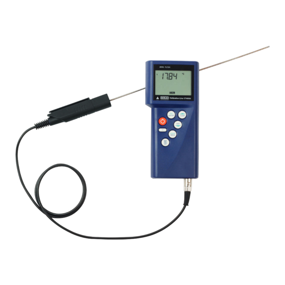
Hand-Held Thermometer Typ CTH6500, präzise Ausführung, inkl. 9-V-Blockbatterie ■ Kalibrierzertifikat 3.1 nach DIN EN 10204 ■ Temperaturfühler nach Wahl ■ Lieferumfang mit dem Lieferschein abgleichen. 4.3 Bedien- und Anzeigeelemente Fühlerhalterung Erster Anschlussport für Temperaturfühler WIKA Betriebsanleitung, Typen CTH6300 und CTH6500...
Pfeiltaste FAST Auswahl der Menüpunkte ENTER/MENU-Taste Zugang zum Hauptmenü, Bestätigen der Funktion MIN/MAX/HOLD/AVE-Taste Einstellen von MIN und MAX, HOLD und AVE Funktionstasten Konfigurieren des Gerätes EIN-/AUS-Taste Ein- und Ausschalten des Gerätes ESC-Taste Zurück zum Messmodus WIKA Betriebsanleitung, Typen CTH6300 und CTH6500...
Akku vollständig zu laden. Wird das Gerät längere Zeit nicht benutzt, die Batterie herausnehmen. Beim Schließen des Batteriefaches darauf achten, dass die Batteriean- schlussdrähte nicht gequetscht oder beschädigt werden. WIKA Betriebsanleitung, Typen CTH6300 und CTH6500...
Stecker nicht verkantet anstecken. Bei richtig angesetztem Stecker kann dieser ohne ■ größeren Kraftaufwand eingesteckt werden. Beim Abstecken des Fühlers nicht am Kabel ziehen, sondern nur an der Steckerhülse. ■ 4.9 Steckerbelegung 4.9.1 Fühleranschluss Pt100 4-Leiter Messkanal 1 und 2 Pt100 4-Leiter Lötseite WIKA Betriebsanleitung, Typen CTH6300 und CTH6500...
Typ K grün grün gelb NiCr-Ni + grün - weiß + rot - grün + gelb - rot Typ N rosa NiCrSi-NiSi + rosa - weiß Typ L braun Fe-CuNi + rot - blau WIKA Betriebsanleitung, Typen CTH6300 und CTH6500...
4.9.3 Fühleranschluss Flügelrad Mini Air Messkanal 1 und 2 Lötseite gelb weiß schwarz Mini Air Flügelrad 4.9.4 Adapter DIN-Stecker auf Thermoelementbuchse Messkanal 1 und 2 Pt100 2-Leiter Lötseite gn (ws) Miniatur-Thermo- elementbuchse rt (gn) Kabellänge 12 cm WIKA Betriebsanleitung, Typen CTH6300 und CTH6500...
3. Bei längerer Einlagerung (mehr als 30 Tage) einen Beutel mit Trocknungsmittel der Verpackung beilegen. WARNUNG! Vor der Einlagerung des Gerätes (nach Betrieb) alle anhaftenden Messstoffreste entfernen. Dies ist besonders wichtig, wenn der Messstoff gesundheitsgefährdend ist, wie z. B. ätzend, giftig, krebserregend, radioaktiv, usw. WIKA Betriebsanleitung, Typen CTH6300 und CTH6500...
Zeile 1: CoFF P = Kalibrierung auf Kanal 1 nach DIN, Fühlerauswahl auf Pt100 einge- stellt. Kanal 2 Zeile 2: CoFF P = Kalibrierung auf Kanal 2 nach DIN, Fühlerauswahl auf Pt100 einge- stellt. WIKA Betriebsanleitung, Typen CTH6300 und CTH6500...
Mit Hilfe der Pfeiltasten ▲▼ werden die gewünschten Menüpunkte ausgewählt. ■ Durch Betätigen der ESC-Taste gelangt man zurück in den Messmodus. ■ 6.4 Menübaum Unit Prob Lin2 Chnl ArEA °C T1-T2 °F g/m³ °C td °F td m³/s WIKA Betriebsanleitung, Typen CTH6300 und CTH6500...
Auf der linken Displayseite erscheint eine kleine 1, die den Kanal anzeigt. 3. Mit den Pfeiltasten ▲▼ den Kanal ändern, für den ein Fühler ausgewählt werden soll. 4. Mit ENTER/MENU die Auswahl bestätigen. 5. Mit den Pfeiltasten ▲▼ jetzt folgende Fühler auswählen (Siehe nachfolgende Tabelle). WIKA Betriebsanleitung, Typen CTH6300 und CTH6500...
Wird eine Messgröße im Menü Prob verändert und mit der Entertaste bestätigt, wird automatisch die Standardkalibrierung verwendet. Hinweis zum Kombinationsfühler (Temperatur und Feuchte): Sicherstellen, dass als Messgröße „relative Feuchte“ für den Messkanal eingestellt ist, an dem der Kombifühler angeschlossen ist. WIKA Betriebsanleitung, Typen CTH6300 und CTH6500...
B. bei Pt100-Widerstandsmessungen DIN IEC 60751 oP1: Nummernkalibrierung Der 2 x 4-stellige Code ist bei unseren Fühlern auf dem Handgriff gut sichtbar angebracht, entspricht einem 2-Punkteabgleich oP2: Physikalische Kalibrierung Kalibrierung mit Vergleichsnormalen: 1-Punkt-, 2-Punkt- oder 3-Punkteabgleich möglich WIKA Betriebsanleitung, Typen CTH6300 und CTH6500...
Seite 64
3. Mit ESC in den Messmodus zurückkehren. Nummernkalibrierung oP1 1. Mit Hilfe der Pfeiltasten ▲▼ oP1 auswählen. 2. Mit ENTER/MENU die gewünschte Einstellung bestätigen. ⇒ Im unteren Displayteil erscheint eine kleine 1. Dahinter stehen 4 Zeichen WIKA Betriebsanleitung, Typen CTH6300 und CTH6500...
Seite 65
1. Mit Hilfe der Pfeiltasten ▲▼ oP2 auswählen. 2. Mit ENTER/MENU die gewünschte Einstellung bestätigen. ⇒ Im unteren Displayteil erscheint 1 P. 3. Mit den Pfeiltasten ▲▼ zwischen einer 1-Punkt 1 P-, 2-Punkt 2 P- und 3-Punkt 3 P-Kalibrierung auswählen. WIKA Betriebsanleitung, Typen CTH6300 und CTH6500...
Seite 66
⇒ Auf dem Display erscheint Si_. 5. Mit den Pfeiltasten ▲▼ das Vorzeichen auswählen: Si_ = einzugebende Zahl ist im negativen Bereich (unter 0,00 °C) Si ┘ = einzugebende Zahl ist im positiven Bereich WIKA Betriebsanleitung, Typen CTH6300 und CTH6500...
Seite 67
Beispiel der Messwertanzeige nach einer physikalischen Kalibrierung gegen ein Vergleichsnormal: Die kleine 2 in der linken Ecke in Verbindung mit dem Anzeigesegment CAL in der Displaymitte zeigt an, dass die physikalische Fühlerkalibrierung oP2 aktiviert wurde. WIKA Betriebsanleitung, Typen CTH6300 und CTH6500...
Seite 68
6. Inbetriebnahme, Betrieb 6.4.4.1 Kalibrierfunktion Kombifühler (Feuchte/Temperatur) CAL Alle Feuchtefühler der Firma WIKA sind Kombinationsfühler. D. h. neben dem Feuchtesensor beinhalten diese Fühler auch ein Temperatursensor. Beide Messgrößen sind über einen Fühlerstecker an dem gleichen Messkanal angeschlossen. Um die beiden Messgrößen Feuchte und Temperatur zu kalibrieren, muss vorher die Messgröße rH (rel.
1. Die Taste ENTER/MENU drücken und Chnl mit Hilfe der Pfeiltasten ▲▼ auswählen. 2. Die Taste ENTER/MENU erneut drücken. ⇒ Auf der linken Displayseite erscheint eine kleine 1, die den Kanal anzeigt. 3. Mit den Pfeiltasten ▲▼ den Kanal auswählen der aktiviert oder deaktiviert werden soll. WIKA Betriebsanleitung, Typen CTH6300 und CTH6500...
7. Mit der Pfeiltaste ▲ die blinkende Zahl verändern. 8. Mit der Pfeiltaste ▼ an die nächste Stelle springen. 9. Mit ENTER/MENU die Eingabe bestätigen. 10. Mit ESC in den Messmodus zurückkehren. MENÜ Unit Prob Lin2 Chnl ArEA WIKA Betriebsanleitung, Typen CTH6300 und CTH6500...
6. Inbetriebnahme, Betrieb 6.4.7 Speicherverwaltung [Lo6] (nicht möglich bei CTH6300) 1. Die Taste ENTER/MENU drücken und Lo6 mit Hilfe der Pfeiltasten ▲▼ auswählen (nur wenn die Datenlogger-Ausführung bestellt wurde). 2. Die Taste ENTER/MENU erneut drücken. ⇒ In der unteren Displayzeile erscheint OFF.
Auf dem Display wird dAoF angezeigt. Die Auto-Off-Funktion ist jetzt deaktiviert. 2. Die Taste ESC-AUTO-OFF drücken. ⇒ Auf dem Display wird EAoF angezeigt. Das Messgerät schaltet sich jetzt nach 30 Minuten automatisch ab. dAoF = Disable Auto-off EAoF = Enable Auto-off WIKA Betriebsanleitung, Typen CTH6300 und CTH6500...
Durch langes Drücken (ca. 3 Sekunden) der Hold-Taste wird der 2. Messkanal deaktiviert bzw. aktiviert. 7. Schnittstellenprotokoll USB Bei der Geräteserie CTH6x00 wird ein USB-/RS-232-Treiber vom Hersteller FTDI verwendet. Parameter Baudrate 2.400 baud Datenbits Stopbits Parity None WIKA Betriebsanleitung, Typen CTH6300 und CTH6500...
Die Daten werden im nachfolgendem Format vom Gerät gesendet. Datentyp = String Die Stringlänge ist abhängig ob es ein 1-Kanal- oder ein 2-Kanalgerät ist. Der String kann bei einem 2-Kanalgerät max. 18 Byte lang sein. WIKA Betriebsanleitung, Typen CTH6300 und CTH6500...
Hersteller rekalibrieren zu lassen. Die Grundeinstellungen werden wenn notwendig korrigiert. 9. Störungen Bei Fehlbedienungen oder Gerätestörungen unterstützt das Gerät den Bediener durch folgende Fehlermeldungen. Anzeige Ursache Maßnahmen open Falscher Fühler oder kein Fühler Richtigen Fühler oder Fühler an- angeschlossen schließen. WIKA Betriebsanleitung, Typen CTH6300 und CTH6500...
Seite 76
Können Störungen mit Hilfe der oben aufgeführten Maßnahmen nicht besei- tigt werden, ist das Hand-Held Thermometer unverzüglich außer Betrieb zu setzen. In diesem Falle Kontakt mit dem Hersteller aufnehmen. Bei notwendiger Rücksendung die Hinweise unter Kapitel 10.2 „Rücksen- dung“ beachten. WIKA Betriebsanleitung, Typen CTH6300 und CTH6500...
Vor der Demontage den Temperaturfühler ausreichend abkühlen lassen! 10.2 Rücksendung WARNUNG! Beim Versand des Gerätes unbedingt beachten: Alle an WIKA gelieferten Geräte müssen frei von Gefahrstoffen (Säuren, Laugen, Lösungen, etc.) sein. Zur Rücksendung des Gerätes die Originalverpackung oder eine geeignete Transportverpackung verwenden.
Transportkoffer, robust ■ Kofferset mit Akku, Ladegerät, Netzteil, Schnittstellenkabel und Software ■ Kofferset mit Netzteil AC 100 ... 260 V, Schnittstellenkabel und Software ■ Software DE-Graph Software ■ PC-Adapterkabel USB ■ Sonstiges DKD/DAkkS-Kalibrierzertifikat ■ WIKA Betriebsanleitung, Typen CTH6300 und CTH6500...
Seite 79
6.4.6 Ingresso area per portata [ArEA] ... . . 108 6.4.7 Gestione dell’archivio [Lo6] (non possibile per CTH6300) ..109 WIKA manuale d’uso modelli CTH6300 e CTH6500...
Seite 80
10.3 Smaltimento ..... 116 11. Accessori La dichiarazione di conformità è disponibile online sul sito www.wika.it. WIKA manuale d’uso modelli CTH6300 e CTH6500...
1. Informazioni generali 1. Informazioni generali I termometri portatili modello CTH6300 e CTH6500 descritti in questo manuale ■ d’uso sono stati progettati e costruiti secondo lo stato dell’arte della tecnica. Tutti i componenti sono sottoposti a severi controlli di qualità e ambientali durante la produzione.
La non osservanza può condurre a ferite gravi o danni alle apparecchiature. Altre importanti norme di sicurezza sono riportate nei singoli capitoli di questo manuale d'uso. WIKA manuale d’uso modelli CTH6300 e CTH6500...
è in grado di portare a termine il lavoro e riconoscere autonomamente potenziali pericoli. Eventuali condizioni operative speciali richiedono inoltre conoscenze specifiche, es. fluidi aggressivi. WIKA manuale d’uso modelli CTH6300 e CTH6500...
Il funzionamento o il caricamento con un alimentatore difettoso (es. in ■ cortocircuito dalla rete verso l’uscita) può causare tensioni pericolose allo strumento! Utilizzare solo i connettori di rete approvati da WIKA per il termometro di ■ precisione portatile. Non utilizzare mai un caricabatterie danneggiato o usurato.
1 K oltre 1.000 °C (1.832 °F) Termocoppie tipo R e S 1 K + 0,1 % della lettura 1 K + 0,1 % della lettura Umidità 1,5 % u.r. Portata 0,5 % del valore di fondo scala WIKA manuale d’uso modelli CTH6300 e CTH6500...
Seite 86
1 anno (a seconda delle condizioni d'uso) consigliato Per le omologazioni e i certificati, consultare il sito internet Per ulteriori informazioni tecniche, fare riferimento alla scheda tecnica WIKA CT 51.05 e CT 55.10 e ai documenti d’ordine. WIKA manuale d’uso modelli CTH6300 e CTH6500...
TC K, d = 3 mm, l = 500 mm (d = 0,12 in, l = 19,69 in) -200 ... +1.100 -392 ... +2.012 Dimensioni in mm (in) Vista frontale Vista laterale (sinistra) 93 (3.66) 44 (1.73) 83 (3.27) 37 (1.46) WIKA manuale d’uso modelli CTH6300 e CTH6500...
In questo modo è possibile ridurre al minimo gli errori di misura e garantire un’elevata precisione di indicazione. Termometro portatile, modello CTH6300, versione industriale Le dimensioni del CTH6300 lo rendono idoneo soprattutto per la messa in servizio, la manutenzione l’assistenza/la taratura di strumenti e attrezzature di temperatura. Termometro portatile, modello CTH6500, versione di precisione Grazie alla sua elevata precisione di 0,03 K nel campo -100 ...
Scelta delle sonde di temperatura ■ Controllare lo scopo di fornitura con il documento di consegna / trasporto. 4.3 Elementi di comando e di visualizzazione Supporto sonda Porta di connessione 1 per sonda di temperatura WIKA manuale d’uso modelli CTH6300 e CTH6500...
Accesso al menu principale, conferma della funzione Tasto MIN/MAX/HOLD/AVE Impostazione di MIN e MAX, HOLD e AVE Tasti funzione Configurazione dello strumento Tasto ON/OFF Accensione e spegnimento dello strumento Tasto ESC Ritorno alla modalità di misura WIKA manuale d’uso modelli CTH6300 e CTH6500...
è comunque sufficiente per caricare la batteria appieno. Se lo strumento non viene utilizzato per un lungo periodo, rimuovere la batteria. Nel chiudere il vano batterie, accertarsi che i fili di collegamento delle batterie non vengano schiacciati o danneggiati. WIKA manuale d’uso modelli CTH6300 e CTH6500...
Fig. in basso: sonda a immersione Ulteriori sonde di temperatura per modello CTH6500 Sezione della sonda combinata temperatura- umidità Fig. in alto: sonda combinata temperatura-umidità Fig. in basso: sonda di flusso a elica WIKA manuale d’uso modelli CTH6300 e CTH6500...
Per scollegare la sonda, non tirare il cavo, ma piuttosto solo il manicotto del ■ connettore. 4.9 Configurazione connettore 4.9.1 Collegamento della sonda, Pt100, a 4 fili Canale di misura 1 e 2 Pt100 a 4 filli Lato della brasatura WIKA manuale d’uso modelli CTH6300 e CTH6500...
Tipo K verde verde giallo NiCr-Ni + verde - bianco + rosso - verde + giallo - rosso Tipo N rosa NiCrSi-NiSi + rosa - bianco Tipo L marrone Fe-CuNi + rosso - blu WIKA manuale d’uso modelli CTH6300 e CTH6500...
4.9.4 Adattatore, connettore DIN al terminale della termocoppia Canale di misura 1 e 2 Pt100 a 2 filli Lato della brasatura gn (ws) Terminale in miniatura della termocoppia rt (gn) Lunghezza del cavo 12 cm WIKA manuale d’uso modelli CTH6300 e CTH6500...
ATTENZIONE! Prima di conservare lo strumento (dopo averlo utilizzato), rimuovere qualsiasi fluido residuo. Questo è particolarmente importante nel caso il fluido sia pericoloso per la salute, es. caustico, tossico, cancerogeno, radioattivo, ecc. WIKA manuale d’uso modelli CTH6300 e CTH6500...
Riga 1: CoFF P = taratura sul canale 1 secondo DIN, selezione della sonda impostata su Pt100. Canale 2 Riga 2: CoFF P = taratura sul canale 2 secondo DIN, selezione della sonda impostata su Pt100. WIKA manuale d’uso modelli CTH6300 e CTH6500...
I tasti a freccia ▲▼ vengono utilizzati per selezionare gli elementi desiderati del menu. ■ Premendo ESC si ritorna alla modalità di misura. ■ 6.4 Menu ad albero Unit Prob Lin2 Chnl ArEA °C T1-T2 °F g/m³ °C td °F td m³/s WIKA manuale d’uso modelli CTH6300 e CTH6500...
3. Utilizzando i tasti a freccia ▲▼, commutare il canale per il quale dovrebbe essere selezionata una sonda. 4. Confermare la selezione premendo ENTER/MENU. 5. Selezionare le seguenti sonde utilizzando i tasti a freccia ▲▼ (vedere tabella seguente): WIKA manuale d’uso modelli CTH6300 e CTH6500...
Seite 100
Enter, la taratura standard viene usata automaticamente. Nota sulle sonde combinate (temperatura e umidità): Assicurarsi che la “umidità relativa” sia impostata come parametro di misura per il canale di misura al quale la sonda combinata è collegata. WIKA manuale d’uso modelli CTH6300 e CTH6500...
Il codice a 2 x 4 cifre, chiaramente e visibilmente visualizzato sulle impugnature delle nostre sonde, corrisponde a una taratura a 2 punti oP2: Taratura fisica Taratura con standard di riferimento: taratura possibile a 1 punto, 2 o 3 punti WIKA manuale d’uso modelli CTH6300 e CTH6500...
Seite 102
1. Utilizzare i tasti freccia ▲▼ per selezionare oP1. 2. Confermare l’impostazione desiderata premendo ENTER/MENU. ⇒ Nella parte inferiore dello schermo appare un piccolo 1. 4 caratteri lo seguono (codice esa/0 ... F). WIKA manuale d’uso modelli CTH6300 e CTH6500...
Seite 103
Nella parte inferiore dello schermo viene visualizzato 1 P. 3. Utilizzare i tasti freccia ▲▼ per selezionare una taratura a 1 punto 1 P, a 2 punti 2 P e a 3 punti 3 P. WIKA manuale d’uso modelli CTH6300 e CTH6500...
Seite 104
5. Utilizzare i tasti freccia ▲▼ per selezionare il segno: Si_ = il numero da inserire è compreso nell’intervallo negativo (inferiore a 0,00 °C) Si ┘ = il numero da inserire è compreso nell’intervallo positivo WIKA manuale d’uso modelli CTH6300 e CTH6500...
Seite 105
Esempio della visualizzazione del valore misurato dopo una taratura fisica rispetto a uno standard di riferimento: Il piccolo 2 nell’angolo sinistro, assieme al segmento CAL visualizzato al centro dello schermo, indica che la taratura fisica della sonda oP2 è stata attivata. WIKA manuale d’uso modelli CTH6300 e CTH6500...
Seite 106
6. Messa in servizio, funzionamento 6.4.4.1 Sonda di taratura a funzionamento combinato (umidità/temperatura), CAL Tutte le sonde di umidità prodotte da WIKA sono sonde combinate. Ciò significa che, oltre al sensore di umidità, esse comprendono anche un sensore di temperatura. Entrambi i parametri di misura sono collegati allo stesso canale di misura utilizzando un connettore di sonda.
Sul lato sinistro dello schermo appare un piccolo 1, che indica il canale. 3. Utilizzare i tasti freccia ▲▼ per selezionare il canale da attivare o disattivare. 4. Confermare la selezione premendo ENTER/MENU. WIKA manuale d’uso modelli CTH6300 e CTH6500...
7. Modificare il numero lampeggiante premendo il tasto a freccia ▲. 8. Premere il tasto freccia ▼ per passare alla posizione successiva. 9. Confermare l’inserimento premendo ENTER/MENU. 10. Premere ESC per tornare alla modalità di misura. MENU Unit Prob Lin2 Chnl ArEA WIKA manuale d’uso modelli CTH6300 e CTH6500...
6. Messa in servizio, funzionamento 6.4.7 Gestione dell’archivio [Lo6] (non possibile per CTH6300) 1. Premere il tasto ENTER/MENU e selezionare Lo6 utilizzando i tasti freccia ▲▼ (solo quando è stata ordinata la versione con data logger). 2. Premere il tasto ENTER/MENU di nuovo.
Ora la funzione Auto-off è disattivata. 2. Premere il tasto ESC/AUTO-OFF. ⇒ EAoF viene visualizzato sul display. Lo strumento di misura viene spento automaticamente dopo 30 minuti. dAoF = disabilitare Auto-off EAoF = abilitare Auto-off WIKA manuale d’uso modelli CTH6300 e CTH6500...
7. Protocollo di interfaccia USB Con la serie di strumenti CTH6x00, viene utilizzato un driver USB-/RS-232 del fabbricante FTDI. Parametri Velocità di 2.400 baud trasmissione Bit dati Bit di stop Parità Nessuno WIKA manuale d’uso modelli CTH6300 e CTH6500...
Seite 112
La lunghezza della stringa dipende dalla questione se si tratti di uno strumento a 1 o 2 canali. Con uno strumento a 2 canali, la stringa può essere al massimo di 18 caratteri. WIKA manuale d’uso modelli CTH6300 e CTH6500...
In caso di malfunzionamento o guasto, lo strumento aiuta l’operatore mediante i seguenti messaggi di errore. Display Causa Rimedi open Collegata sonda errata o nessuna Collegare la sonda o collegare quella sonda corretta. WIKA manuale d’uso modelli CTH6300 e CTH6500...
Seite 114
Se i guasti non possono essere eliminati tramite le misure sopra elencate, il termometro portatile deve essere spento immediatamente. In questo caso, contattare il costruttore. Se è necessario restituire lo strumento, seguire le istruzioni riportate nel capitolo 10.2 “Resi”. WIKA manuale d’uso modelli CTH6300 e CTH6500...
Osservare attentamente lo seguenti indicazioni per la spedizione dello strumento: Tutti gli strumenti spediti a WIKA devono essere privi di qualsiasi tipo di sostanza pericolosa (acidi, basi, soluzioni, ecc.). In caso di reso, utilizzare l'imballo originale o un imballo idoneo per il trasporto.
Valigetta con batteria ricaricabile, caricatore, alimentatore, cavo d’interfaccia e ■ software Valigetta con alimentatore 100 ... 260 Vca, cavo d’interfaccia e software ■ Software Software DE-Graph ■ Adattatore cavo USB per PC ■ Altro Certificato di taratura DKD/DAkkS ■ WIKA manuale d’uso modelli CTH6300 e CTH6500...
Seite 117
WIKA manuale d’uso modelli CTH6300 e CTH6500...
Seite 118
WIKA manuale d’uso modelli CTH6300 e CTH6500...
Seite 119
WIKA manuale d’uso modelli CTH6300 e CTH6500...
Seite 120
WIKA subsidiaries worldwide can be found online at www.wika.com. WIKA-Niederlassungen weltweit finden Sie online unter www.wika.de. Per le filiali WIKA nel mondo, visitate il nostro sito www.wika.it. WIKA Alexander Wiegand SE & Co. KG Alexander-Wiegand-Straße 30 63911 Klingenberg • Germany Tel.