Inhaltsverzeichnis
Werbung
Verfügbare Sprachen
Verfügbare Sprachen
Quicklinks
VECTRON G 06.1200 DUO-PLUS
VECTRON G 06.1600 DUO-PLUS
VECTRON G 06.2100 DUO-PLUS
Betriebsanleitung
Für die autorisierte Fachkraft
Gasgebläsebrenner .............................2-21
Operating instructions
For the authorized specialist
Gas burners .......................................22-41
Ersatzteilliste
Spare parts list
Pièces de rechange
Wisselstukkenlijst .............................43-54
Elektro- und Hydraulikschema
Electric and hydraulic diagrams
Schémas électr. et hydraulique
Elektr. en hydraulische schema
05/2005 - Art. Nr. 13 018 114A
DE
EN
}
Art. Nr.
13 018 315
Werbung
Kapitel
Inhaltsverzeichnis

Verwandte Anleitungen für elco VECTRON G 06.1200 DUO-PLUS


Inhaltszusammenfassung für elco VECTRON G 06.1200 DUO-PLUS
- Seite 1 VECTRON G 06.1200 DUO-PLUS VECTRON G 06.1600 DUO-PLUS VECTRON G 06.2100 DUO-PLUS Betriebsanleitung Für die autorisierte Fachkraft Gasgebläsebrenner ......2-21 Operating instructions For the authorized specialist Gas burners ........22-41 Ersatzteilliste Spare parts list Pièces de rechange Wisselstukkenlijst ......43-54 Elektro- und Hydraulikschema Electric and hydraulic diagrams Art.
-
Seite 2: Inhaltsverzeichnis
Feuerungsautomat ....11 Montage Brennermontage ....12 VECTRON G 06.1200 DUO-PLUS Gasarmaturmontage, Dichtheitskontrollgerät . . . 13 VECTRON G 06.1600 DUO-PLUS Prüfung / Einstellung . -
Seite 3: Übersicht
Übersicht Technische Daten Arbeitsfelder G 06.1200 DUO-PLUS G 06.1600 DUO-PLUS G 06.2100 DUO-PLUS Brennerleistung min.-max. 230 - 1200 230 - 1600 260 - 2100 Regelbereich 1 : 3 * Gasfließdruck mbar 20 - 50- 100 Gasarmaturengruppe MBVEF 412 / MBVEF 420 / VGD20 Rp2 / VGD40 DN65 Brennstoff Erdgas (LL, E) H = 8,83 - 10,35 kWh/m... -
Seite 4: Gasarmaturenauswahl
Übersicht Gasarmaturenauswahl · Achtung: inkl. aller hier enthaltener Armaturen Der hieraus ermittelte Gasfließdruck ist · (Absperrventile, Kompensator, Gaszähler, am Eingang der Gasarmatur einzuhalten. Dem in Tabelle angegebenen TAS, zusätzlicher Filter, etc.) zu Für die Ermittlung des an der Druckverlust ist der Feuerraumdruck des berücksichtigen. -
Seite 5: Brennerbeschreibung
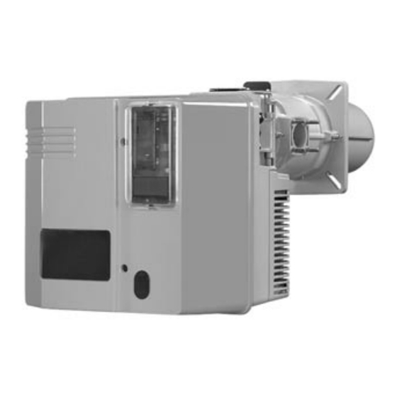
Übersicht Brennerbeschreibung Feuerungsautomat Ionisationsbrücke Luftdruckwächter Motorschutzrelais Motorschutz Relais Brennermotor Zündtransformator (verdeckt) Schaltfeld Stellantrieb Luftklappe Flammrohr Brennerhaube Luftkasten 05/2005 - Art. Nr. 13 018 114A... -
Seite 6: Abmessungen
Übersicht Maßbild und Abmessungen G 06.1200/1600/2100 DUO-PLUS mit Gasarmatur MBVEF 412 und MBVEF 420 MBVEF 412 MBVEF 420 — — — Abstände Für Servicearbeiten ist ein freier Abstand von min. 0,6m auf jeder Seite des Brenners sicherzustellen. Gasarmaturgruppe Montage sowohl links als auch rechts möglich. - Seite 7 Übersicht Maßbild und Abmessungen G 06.1200/1600/2100 DUO-PLUS mit Gasarmatur VGD20 - Rp2 und VGD40 - DN65 VGD20 Rp2 VGD40 DN65 DN65 Abstände Für Servicearbeiten ist ein freier Abstand von min. 0,6m auf jeder Seite des Brenners sicherzustellen. Gasarmaturgruppe Montage sowohl links als auch rechts möglich.
-
Seite 8: Funktion
Funktion Kompaktarmatur MBVEF Elektroanschluß des Gasdruckwächters (DIN 43650) Elektroanschluß der Magnetventile (DIN 43650) Gasdruckwächter Eingangsflansch Druckmeßnippel R1/8, vor Filter (beidseitig) Filter (unter Deckel) Typenschild Anschluß Luftdruckleitung pL, R 1/8 Einstellschraube für Verhältnis V Druckmeßnippel pe, vor Ventil 1, beidseitig Gasdruckmeßnippel M4 nach Ventil 2 Einstellschraube Nullstellung N Die Gaskompaktarmatur MBVEF ist die... -
Seite 9: Gasarmatur Vgd Mit Skp 70 Regler
Funktion Gasarmatur VGD mit SKP 70 Regler Elektroanschluß des Gasdruckwächters (DIN 43650) Elektroanschluß der Magnetventile (DIN 43650) Gasdruckwächter Eingangsflansch Druckmeßnippel R1/8, vor Filter Filter (unter Deckel) Typenschild Anschluß Luftdruckleitung pL, R 1/8 Einstellschraube für Verhältnis V Einstellschraube Nullstellung N Anschluß Feuerraumdruckleitung pF, R1/8 Anschluß... -
Seite 10: Schaltfeld Tc
Funktion Schaltfeld TC Funktion Genormte Einbaustellen 48x48 oder 48x96 mm für den Einbau eines Leistungsreglers (Option) A4.1 Einbaustelle mit Klips für Anzeigeeinheit B10 Messbrücke [µA DC] für Zellenstrom, Anordnung neben dem Motorschütz F10 Sicherung Hauptschalter Ein, grüne Kontroll-Lampe H10 leuchtet Wahl der Leistungsregelung Handbetrieb Auto Vorort-Automatikbetrieb... -
Seite 11: Kenndaten Des Feuerungsautomaten Sg 513 Programmablauf Des Feuerungsautomaten
Funktion Kenndaten des Feuerungsautomaten SG 513 Programmablauf des Feuerungsautomaten Der Gasfeuerungsautomat SG 513 steuert und Drücken Sie auf … führt zu … überwacht den Gebläsebrenner. Durch den den Knopf R mikroprozessor-gesteuerten Programmablauf ergeben sich äußerst stabile Zeiten, unabhängig von während ... Schwankungen der Netzspannung oder der …... -
Seite 12: Brennermontage
Montage Brennermontage Montage Brennkopf Langlöcher auf das erforderliche · Brennerplatte/Kesseltüre gemäß Maß ausschneiden. · Brennkopf mit 4 Sechskantmuttern nebenstehender Zeichnung vorbereiten. M12 befestigen. · Innendurchmesser a Ø 250 mm · Der Raum zwischen Flammrohr und Türisolierung ist mit feuerfestem festlegen. ·... -
Seite 13: Gasarmaturmontage, Dichtheitskontrollgerät
Montage Gasarmaturmontage Dichtheitskontrollgerät VPS 504 S01 · Bei SKP 70 das mitgelieferte Montage Gasarmatur SKP70/MBVEF · Die richtige Einbaulage des Sicherheitsmagnetventil (Bausatz) mit Spule nach oben montieren, den O-Ringes B im Gasanschlußflansch mitgelieferten Gasfilter (Bausatz) C überprüfen. · Die Gasarmatur mit Muttern M10 so waagerecht mit obenliegendem Deckel (2 Messanschlüsse) befestigen, daß... -
Seite 14: Prüfung / Einstellung
Montage Kontrolle Mischeinrichtung Sekundärluft Einstellung Mischeinrichtung für Erdgas / Flüssiggas Kontrolle Mischeinrichtung · Sicherungsschraube D lösen (S. Seite 12). · Mobile Achse E entfernen. · Brennergehäuse öffnen. · Zünd- und Ionisationskabel lösen. · Die vier Schrauben der Einstellplatte (RTC) um 2 Umdrehungen lösen. ·... -
Seite 15: Gasversorgung, Elektrische Versorgung
Montage Gasversorgung Elektrische Versorgung Prüfung vor Inbetriebnahme Bei der Inbetriebnahme des Brenners Allgemeine Vorschriften für die wird gleichzeitig die Anlage unter der Gasversorgung · Der Anschluss der Gasarmatur an Verantwortung des Installateurs oder seines Stellvertreters abgenommen. Er das Gasnetz darf nur von einer allein kann gewährleisten, dass die anerkannten Fachkraft durchgeführt Anlage den geltenden Normen und... -
Seite 16: Brennereinstelldaten
Inbetriebnahme Brennereinstelldaten Luftregulierung Luftklappenstellung (°) Brenner- Maß leistung Zündlast Vollast Nocke III Nocke I G 06.1200 DUO-PLUS 1100 1200 1100 G 06.1600 DUO-PLUS 1300 1600 1150 1400 1700 G 06.2100 DUO-PLUS 1900 2100 Obige Einstelldaten sind Grundeinstellungen. Die Werkseinstelldaten sind fett umrandet. Mir diesen Einstellungen kann im Normalfall der Brenner in Betrieb genommen werden. - Seite 17 Inbetriebnahme Luftregulierung Luftregulierung über Luftklappe Diese wird über den Stellmotor Y10 angetrieben. Die Position der Luftklappe wird durch Einstellung der Nocken I - IV festgelegt. Stellindex der Nocken Vier einstellbare Nocken Schlüssel zur Nockeneinstellung Scheibe mit Skala ; gibt Stellung der Luftklappe an Knopf zur Entkupplung der Luftklappe von Stellantrieb Anschlußleiste...
-
Seite 18: Einregulierung Des Brenners
Inbetriebnahme Einregulierung des Brenners Einstellung Gasdruckwächter, Luftdruckwächter Funktionskontrolle · Haben sich die Meßwerte durch Einregulierung des Brenners – bei MB VEF Ventil auf Schraube V · Gaskugelhahn öffnen. wirken. Höheres CO in Richtung Verstellen der Schraube D beim · Gas- und Luftdruckwächter auf grösserer Skalenwert. -
Seite 19: Wartung
Service Wartung Servicearbeiten an Kessel und Brenner führt ausschließlich die geschulte Fachkraft durch. Um eine turnusgemäße Durchführung der Servicearbeiten zu gewährleisten sollte dem Betreiber der Anlage der Abschluß eines Wartungsvertrages empfohlen werden. · Vor Wartungs- und Reinigungsarbeiten, Strom abschalten. · Handabsperrventil schließen ·... - Seite 20 Service Wartung Flammrohr demontieren Ventile Filteraustausch Gas Dieser Arbeitsvorgang macht entweder Die Ventile erfordern keine besondere Der Filtereinsatz muß einmal jährlich das Öffnen der Feuerraumtür oder die Wartung. kontrolliert und wenn verschmutzt Demontage des Brenners erforderlich. Es ist keine Reparatur an einem Ventil ausgetauscht werden.
-
Seite 21: Störungsbeseitigung
Service Störungsbeseitigung Ursachen und Beseitigung von Wenn die Störung weiter besteht: Nur Originalersatzteile · Die vom Feuerungsautomat Störungen verwenden. Bei Störungen müssen die abgegebenen Blink-Codes beachten grundsätzlichen Voraussetzungen zum und ihre Bedeutung aus Hinweis: ordnungsgemäßen Betrieb kontrolliert nachstehender Tabelle entnehmen. Nach jedem Eingriff: Mit dem als Zubehör erhältlichen ·... - Seite 53 05/2005 - Art. Nr. 13 018 114A...
- Seite 54 Maintenance parts are parts which should be replaced on a preventive basis during maintenance when reassembling disassembled parts (sealing components for example).. For wear parts and maintenance parts, ELCO ’s performance warranty for them over time under commercial conditions does not apply.
- Seite 55 05/2005 - Art. Nr. 13 018 114A...
- Seite 56 Adresse Service-Hotline ELCO Austria GmbH 0810-400010 Aredstr.16-18 2544 Leobersdorf ELCO Belgium n.v./s.a. Pontbeeklaan-53 02-4631902 1731 Zellik ELCOTHERM AG Sarganserstrasse 100 0848 808 808 7324 Vilters ELCO GmbH 0180-3526180 Dreieichstr.10 64546 Mörfelden-Walldorf ELCO France 18 rue des Buchillons 0450877624 74106 Annemasse ELCO-Rendamax B.V.