Herunterladen Diese Seite drucken
Vorschau ausblenden Andere Handbücher für VAMP-X:

Werbung

Verfügbare Sprachen
  • DE

Verfügbare Sprachen

  • DEUTSCH, seite 9
VAMP-X
3004239
USER MANUAL
Quick Guide
Original language
REFCO Manufacturing Ltd.
Industriestrasse 11
Hitzkirch – Switzerland
www.refco.ch
REFCO Manufacturing (US) Inc.
66 B Industry Avenue
Springfield MA 01104
www.refcoswiss.com
EN
REFCO M
66 B Indu
Springfie
www.refc

Werbung

loading

Inhaltszusammenfassung für Refco VAMP-X

  • Seite 1 VAMP-X Quick Guide 3004239 Original language REFCO M 66 B Indu Springfie www.refc USER MANUAL REFCO Manufacturing Ltd. Industriestrasse 11 Hitzkirch – Switzerland www.refco.ch REFCO Manufacturing (US) Inc. 66 B Industry Avenue Springfield MA 01104 www.refcoswiss.com...
  • Seite 2 Commissioning Indoor unit Install posable hose with included filter to drain pan outlet. Retain required water columns on filter. Install minimum height of 5 mm or 20 mm, respectively. Manufacturing (US) Inc. More details can be found in the user manual. ustry Avenue eld MA 01104 coswiss.com...
  • Seite 3 Commissioning Connect the sensor cable to the pump. Connect the suction tube from the sensor to the pump. Connect ¼“ / 6 mm discharge tube to outlet connector of pump. Install Anti-Siphon Valve. Do not pull out the discharge tube, remove it only with a knife.
  • Seite 4 Disconnect all electrical power before starting installation, maintenance, or service work. Wire the installation cable to the indoor unit. Make connection between installation cable and pump leader cable. Sensor must be installed horizontally. The pump can be installed both horizontally and vertically. Wiring Example Example diagram for reference purpose only.
  • Seite 5 Intended Use The VAMP-X condensate pump is intended for use as condensate removal unit and must be installed fully within enclosures of electric heat pumps, air-conditioners indoor units and dehumidifiers. This includes ceiling cassettes, underfloor convectors and wall-mounted convectors. It is for indoor use only and it is not submersible.
  • Seite 6 Alarm Relay Operation Table Pump Status Condensate Level Default Operation Not powered Powered Below alarm level Powered Alarm activated LED Indication green Status LED Pattern Reason Miswired, unplugged No Power or no voltage Startup LED Pump is starting Idle No water to pump Pumping Water Pump is running Increased pump...
  • Seite 7 CE, UL778, CSA C22.2 #108, UL 2043 Spare parts and accessories: 4689088 POSABLE-HOSE/4 (with filter) 3004087 KIT-4087 (Star tube & Anti-Siphon) 3004186 STAR-TUBE-600 (15 m) 4679160 PVC-TUBE (¼“ / 6 mm, 30m) 4678597 INLINE-FILTER 4689089 CP-INSTALLATION-CABLE 3004065 HSG-4065/4 (Anti-Siphon) 3004243 VAMP-X-SENSOR...
  • Seite 8 VAMP-X Kurzanleitung 3004239 REFCO M 66 B Indu Springfie www.refc USER MANUAL REFCO Manufacturing Ltd. Industriestrasse 11 Hitzkirch – Switzerland www.refco.ch REFCO Manufacturing (US) Inc. 66 B Industry Avenue Springfield MA 01104 www.refcoswiss.com...
  • Seite 9 Installation Innengerät Installiere den ausziehbaren Flexschlauch inklusive Filter am Kondensatwannenanschluss. Halte minimale Wassersäulen über Filtern ein. Installiere unter Manufacturing (US) Inc. Beachtung der Mindesthöhe von 5 mm oder 20 mm. Weitere ustry Avenue Details findest du in der Bedienungsanleitung. eld MA 01104 coswiss.com Schliesse den ausziehbaren Flexschlauch am Reservoir an.
  • Seite 10 
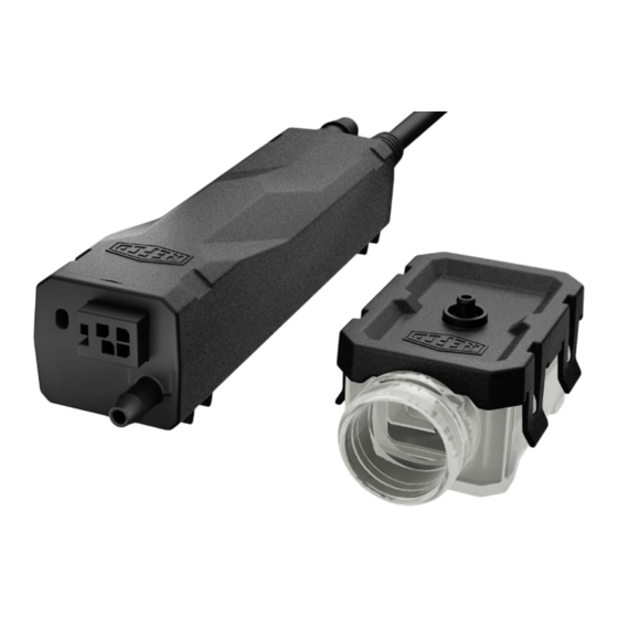
Installation Verbinde das Sensorkabel mit der Pumpe. Verbinde den Saugschlauch vom Sensor mit der Pumpe. Schließe einen ¼“ / 6 mm Abflussschlauch am Ausgangs- anschluss der Pumpe an. Installiere die Siphon-Stopp Vor- richtung. Ziehe den Abflussschlauch nicht heraus, sondern entferne ihn nur mit einem Messer.
  • Seite 11 Trenne alle Verbindungen zum Stromnetz vor Beginn der Installation, Wartung oder Servicearbeiten. Verdrahte das Installationskabel mit dem Innengerät. Verbinde das Installationskabel mit dem Pumpenkabel. Der Sensor muss horizontal installiert werden. Die Pumpe kann sowohl horizontal als auch vertikal installiert werden. Verdrahtungsbeispiel Schutzleiter / Neutralleiter BRAUN...
  • Seite 12 Bestimmungsmässiger Gebrauch Die VAMP-X Kondensatpumpe ist für die Entfernung von Konden- satwasser vorgesehen und muss vollständig innerhalb des Gehäuses einer elektrischen Wärmepumpe, eines Klimaanlagen-Innengeräts und eines Entfeuchters installiert werden. Dazu gehören Kassetten- geräte, Unterflurkonvektoren und wandmontierte Konvektoren. Nur zur Verwendung im Innenbereich. Nicht tauchfähig.
  • Seite 13 Alarmrelais Betriebstabelle Pumpenstatus Kondensatlevel Standardbetrieb Stromlos Mit Strom versorgt Unterh. Alarmstufe Mit Strom versorgt Alarm aktviert LED Betriebstabelle grün Status LED Abfolge Indikation Falsch angeschlossen, Stromlos ausgesteckt, spannungsfrei LED Startfrequenz Pumpe startet Standy Modus Kein Wasser zum Warten auf Wasser Pumpen Pumpe läuft in Pumpt Wasser...
  • Seite 14 CE, UL778, CSA C22.2 #108, UL 2043 Ersatzteile und Zubehör 4689088 POSABLE-HOSE/4 (mit Filter) 3004087 KIT-4087 (Star tube & Anti-Siphon) 3004186 STAR-TUBE-600 (15 m) 4679160 PVC-TUBE (¼“ / 6 mm, 30m) 4678597 INLINE-FILTER 4689089 CP-INSTALLATION-CABLE 3004065 HSG-4065/4 (Anti-Siphon) 3004243 VAMP-X-SENSOR...
  • Seite 15 VAMP-X Guide rapide 3004239 REFCO M 66 B Indu Springfie www.refc USER MANUAL REFCO Manufacturing Ltd. Industriestrasse 11 Hitzkirch – Switzerland www.refco.ch REFCO Manufacturing (US) Inc. 66 B Industry Avenue Springfield MA 01104 www.refcoswiss.com...
  • Seite 16 Installation Unité intérieure Installez le tuyau flexible et extensible avec le filtre sur le raccord de bac à condensats. Retenez les colonnes d‘eau requises sur les filtres. Installez en Manufacturing (US) Inc. respectant une hauteur minimale de 5 mm ou 20 mm, selon ustry Avenue le cas.
  • Seite 17 Installation Connectez le câble du capteur à la pompe. Connectez le tube d‘aspiration du capteur à la pompe. Posez le ¼“ / 6 mm tube de refoulement avec le raccord de sortie. Installez la vanne anti-siphon. Ne retire pas le tube de refoulement, retire-le uniquement avec un couteau.
  • Seite 18 Coupez toutes les connexions au réseau d‘électricité avant de commencer l’installation, la maintenance ou des travaux de service. Branchez le câble d‘installation à l‘unité intérieure. Connectez le câble d‘installation au câble de la pompe. Le capteur doit être installé horizontalement. La pompe peut être installée à...
  • Seite 19 Utilisation conforme La pompe à condensat VAMP-X est destinée à être utilisée comme unité d‘évacuation des condensats et doit être installée entièrement dans les boîtiers des pompes à chaleur électriques, des climatiseurs et des déshumidificateurs. Il s‘agit de cassettes de plafond, d‘onvecteurs de sol et de convecteurs muraux.
  • Seite 20 Table d‘opération de relais d‘alarme État de la pompe Niveu de condensat Opération par défaut Pas alimentée Alimentée Niv. d‘alarme inférieur NC Alimentée Alarm activée Signaux LED service rouge vert État Motif de LED Raison Male connectée, non Pas alimentée connecté...
  • Seite 21 CE, UL778, CSA C22.2 #108, UL 2043 Pièces de rechange et accessoires: 4689088 POSABLE-HOSE/4 (avec filtre) 3004087 KIT-4087 (Star tube & anti-siphon) 3004186 STAR-TUBE-600 (15 m) 4679160 PVC-TUBE (¼“ / 6 mm, 30m) 4678597 INLINE-FILTER 4689089 CP-INSTALLATION-CABLE 3004065 HSG-4065/4 (anti-siphon) 3004243 VAMP-X-SENSOR...
  • Seite 22 VAMP-X Guida rapida 3004239 REFCO M 66 B Indu Springfie www.refc USER MANUAL REFCO Manufacturing Ltd. Industriestrasse 11 Hitzkirch – Switzerland www.refco.ch REFCO Manufacturing (US) Inc. 66 B Industry Avenue Springfield MA 01104 www.refcoswiss.com...
  • Seite 23 Messa in funzione Unità interna Installare il tubo flessibile estensibile con il filtro incluso allo scarico del raccordo di bac à condensats. Mantieni le colonne d‘acqua richieste sui filtri. Installa Manufacturing (US) Inc. rispettando un‘altezza minima di 5 mm o 20 mm, a seconda ustry Avenue del caso.
  • Seite 24 Messa in funzione Collegare il cavo del sensore alla pompa. Collegare il tubo di aspirazione del sensore alla pompa. Collegare il tubo di drenaggio da ¼“ / 6 mm al connettore di scarico sul retro della pompa. Installare la valvola anti-sifone. Non tirare fuori il tubo di drenaggio, rimuovilo solo con un coltello.
  • Seite 25 Scollegare tutta l‘alimentazione elettrica prima di iniziare l‘installazione, la manutenzione o il lavoro di assistenza. Collegare il cavo di installazione all‘unità interna. Collegare il cavo di installazione al cavo della pompa. Il sensore deve essere installato orizzontalmente. La pompa può essere installata sia orizzontalmente che verticalmente. Esempio di cablaggio Conduttore di protezione MARRONE...
  • Seite 26 Uso conforme La pompa di condensato VAMP-X è progettata per l‘uso come unità di rimozione del condensato e deve essere installata completamen- te all‘interno degli involucri di pompe di calore elettriche, unità di condizionamento dell‘aria e deumidificatori. Questo include cassette a soffitto, convettori a pavimento e convettori a parete.
  • Seite 27 Tabella di funzionamento del relè di allarme Stato della pomopa Livello di condensa Modalità predefinita Non alimentato Alimentato Sotto livel. di allarme NC Alimentato Alarme attivato Indicazioni LED rosso verte Stato Schema LED Motivo Errato cablaggio, Non alimentato scollegato o senza tensionee La pompa si sta LED avvio...
  • Seite 28 CE, UL778, CSA C22.2 #108, UL 2043 Parti di ricambio e accessori 4689088 POSABLE-HOSE/4 (con filtro) 3004087 KIT-4087 (Tubo stella e anti-sifone) 3004186 STAR-TUBE-600 (15 m) 4679160 PVC-TUBE (¼“ / 6 mm, 30m) 4678597 INLINE-FILTER 4689089 CP-INSTALLATION-CABLE 3004065 HSG-4065/4 (anti-sifone) 3004243 VAMP-X-SENSOR...
  • Seite 29 VAMP-X Guía rápida 3004239 USER MANUAL REFCO Manufacturing Ltd. Industriestrasse 11 Hitzkirch – Switzerland www.refco.ch REFCO Manufacturing (US) Inc. 66 B Industry Avenue Springfield MA 01104 www.refcoswiss.com...
  • Seite 30 Puesta en funcionamiento Unidad interior Instale la manguera flexible retráctil con el filtro incluido en la salida de la bandeja de drenaje. Mantén las columnas de agua requeridas en los filtros. Instala respetando una altura mínima de 5 mm o 20 mm, según corresponda.
  • Seite 31 Puesta en funcionamiento Conecte el cable del sensor a la bomba. Conecte el tubo de succión del sensor a la bomba. Conecte el tubo de descarga de ¼“ / 6 mm al conector de salida en la parte trasera de la bomba. Instale la válvula anti-sifón.
  • Seite 32 Desconecte toda la alimentación eléctrica antes de comenzar la instalación, el mantenimiento o el trabajo de servicio. Conecte el cable de instalación a la unidad interior. Conecta el cable de instalación con el cable de la bomba. El sensor debe instalarse horizontalmente. La bomba puede instalarse tanto horizontalmente como verticalmente.
  • Seite 33 Intended Use La bomba de condensado VAMP-X está diseñada para su uso como unidad de eliminación de condensados y debe instalarse com- pletamente dentro de los recintos de bombas de calor eléctricas, unidades interiores de aire acondicionado y deshumidificadores. Esto incluye casetes de techo, convectores de suelo y convectores de pared.
  • Seite 34 Table de operación de relé de alarma Estado de la bomba Nivel de conensado Modo estándar Sin energía Energía Bajo nivel de alarma Energía Alarma activada Indicación LED rojo verte Estado Patrón LED Razón ncorrectamente Sin energía cableado, desconecta- do o sin voltaje La bomba está...
  • Seite 35 CE, UL778, CSA C22.2 #108, UL 2043 Piezas de repuesto y accesorios 4689088 POSABLE-HOSE/4 (con filtro) 3004087 KIT-4087 (Tubo estrella/anti-sifón) 3004186 STAR-TUBE-600 (15 m) 4679160 PVC-TUBE (¼“ / 6 mm, 30m) 4678597 INLINE-FILTER 4689089 CP-INSTALLATION-CABLE 3004065 HSG-4065/4 (Anti-sifón) 3004243 VAMP-X-SENSOR...
  • Seite 36 Control number 5009952 REFCO Manufacturing Ltd. Industriestrasse 11 Hitzkirch – Switzerland www.refco.ch REFCO Manufacturing (US) Inc. 66 B Industry Avenue Springfield MA 01104 www.refcoswiss.com...

Diese Anleitung auch für:

3004239