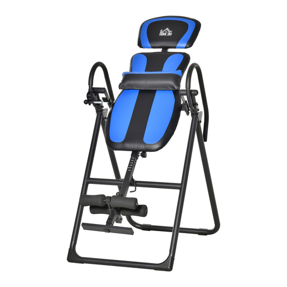
HOMCOM A90-258 Bedienungsanleitung
Vorschau ausblenden
Andere Handbücher für A90-258:
- Bedienungsanleitung (9 Seiten) ,
- Bedienungsanleitung (51 Seiten)

Verwandte Anleitungen für HOMCOM A90-258


Inhaltszusammenfassung für HOMCOM A90-258
- Seite 1 IN230800285V01_UK_DE A90-258 IMPORTANT, RETAIN FOR FUTURE REFERENCE: READ CAREFULLY ASSEMBLY INSTRUCTION...
- Seite 12 IN230800285V01_UK_DE A90-258 WICHTIG - BITTE HEBEN SIE DIESE ANLEITUNG FÜR EINE SPÄTERE BEZUGNAHME AUF: SORGFÄLTIG DURCHLESEN MONTAGEANLEITUNG -12-...
- Seite 13 SORGFÄLTIG LESEN! Bitte bewahren Sie dieses Handbuch zum einfachen Nachschlagen an einem sicheren Ort auf 1.Es ist wichtig, dass Sie dieses Handbuch vor der Montage und der Inbetriebnahme des Geräts vollständig lesen. Eine sichere und effektive Verwendung kann nur erreicht werden, wenn das Gerät ordnungsgemäß...
-
Seite 14: Wartung/Inspektion
PFLEGE Neutrales Reinigungsmittel kann in Wasser verdünnt, verwendet werden, mit dem feuchten Tuch vorsichtig abwischen, und dann mit einem trockenen Tuch trocknen. Verwenden Sie keine alkalischen Lösungsmittel, ätherische Öle und andere Lösungsmittel. WARTUNG/INSPEKTION Vermeiden Sie hohe Temperaturen, Feuchtigkeit oder direkte Sonneneinstrahlung, stellen Sie es bitte an einen gut belüfteten Ort. - Seite 15 Vor der Übung, ist es besser aufzuwärmen. Warme Muskeln strecken leichter, so dass die erste von 5 ~ 10 Minuten zum Aufwärmen verwendet werden. Dann in Übereinstimmung mit den folgenden Methoden Dehnübungen ausführen und unterbrechen - fünfmal wiederholen, jedes Bein jedes Mal 10 Sekunden oder länger, um sie nach dem Ende der Übung zu wiederholen.
-
Seite 16: Beschreibung
Teileliste BESCHREIBUNG Anzahl Nr. BESCHREIBUNG Anzahl Vorderer Stützrahmen 35 x 35 mm rechteckige-Endkappe Verstellbare 33,4 x 33,4 mm eckige Schwenkstange (links) Endkappe Verstellbare Knopf M16 Schwenkstange (Rechts) Hinterer Stützrahmen 20 x 40 mm eckige Endkappe Verstellbare Knöchelstütze Rückenlehnenpolster Höhenverstellbares Rohr Kopfstützenpolster Kopfpolsterrohr Rolle... - Seite 17 52 54 54 52 52 54 -17-...
- Seite 18 Schritt 1 Öffnen Sie den vormontierten Hauptrahmen, der aus den Teilen (01) und (03) besteht. Führen Sie den Sicherungsstift (41) durch die Löcher des vormontierten Hauptrahmens. Schritt 2 Setzen Sie jede verstellbare Schwenkstange (02L) & (02R) in das hintere Stützrohr (03) ein und befestigen Sie sie dann mit 2 Unterlegscheiben (18), 2 Endkappen (19), 2 M8-Unterlegscheiben (52) und 2 M8 x 15 mm Inbusschrauben (46).
- Seite 19 Schritt 3 Setzen Sie das vormontierte Kopfpolsterrohr (06) in den hinteren Polsterrahmen (07) ein und sichern Sie es mit dem M16-Knauf (29). Schritt 4 Montieren Sie den vormontierten Polsterrahmen (07) an jeder verstellbaren Schwenkstange (02L & 02R) und sichern Sie ihn dann mit 4 M8 x 20 mm Inbusschrauben (47), 8 M8-Unter- legscheiben (52) und 4 M8-Nylonmuttern (54).
- Seite 20 Schritt 5 Montieren Sie den linken Lenker (13L) an der linken Seite des Hauptrahmens und befestigen Sie ihn dann mit 2 M8 x 55 mm Inbusschrauben (44), 4 M8-Unterlegscheiben (52) und 2 M8-Nylonmuttern (54). Montieren Sie den rechten Lenker (13R) an der rechten Seite des Hauptrahmens und befesti- gen Sie ihn mit 2 M8 x 55 mm Inbusschrauben (44), 4 M8-Unterlegscheiben (52) und 2 M8-Ny- lonmuttern (54).
- Seite 21 Schritt 7 Montieren Sie das Fußrohr (08) am höhenverstellbaren Rohr (05) und sichern Sie es mit 1 M8 x 45 mm Sechskantschraube (37), 1 M8 Unterlegscheibe (52) und 1 M8 Nylonmutter (54). Schritt 8 Befestigen Sie das höhenverstellbare Rohr (05) am Rückenkissenrahmen (07), indem Sie den M16-Knopf (29) und den Φ8 x 50 mm Sicherungsstift (41) ziehen.
- Seite 22 Sicherheitsschloss Im Lieferumfang ist ein Sicherheitsschloss (11) enthalten, mit dem das Umkehrsystem verriegelt werden kann, wenn es nicht benutzt wird. Dieses Schloss geht in das höhenverstellbare Rohr (05) und dann in den Rahmen. HALTEN SIE DIE SICHERHEITSVERRIEGELUNG IMMER IN DER VERRIEGELTEN POSI- TION, UM IHRE SICHERHEIT UND DIE SICHERHEIT DER PERSONEN IN IHRER UMGE- BUNG ZU GEWÄHRLEISTEN, WENN SIE SICH NICHT UMKEHREN UND/ODER DAS GERÄT NICHT IN GEBRAUCH IST.
- Seite 23 -23-...