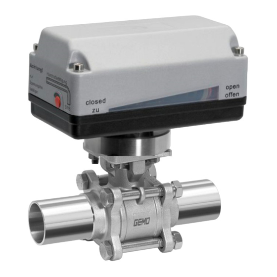
Gemü B52 Betriebsanleitung
Elektromotorisch betätigter kugelhahn
Vorschau ausblenden
Andere Handbücher für B52:
- Betriebsanleitung (53 Seiten) ,
- Beschreibung (32 Seiten)

Verwandte Anleitungen für Gemü B52


Inhaltszusammenfassung für Gemü B52
- Seite 1 GEMÜ B52 Elektromotorisch betätigter Kugelhahn Motorized ball valve Betriebsanleitung Operating instructions Weitere Informationen Webcode: GW-B52...
- Seite 2 Alle Rechte, wie Urheberrechte oder gewerbliche Schutzrechte, werden ausdrücklich vorbehalten. All rights including copyrights or industrial property rights are expressly reserved. Dokument zum künftigen Nachschlagen aufbewahren. Keep the document for future reference. © GEMÜ Gebr. Müller Apparatebau GmbH & Co. KG 07.03.2023 GEMÜ B52 2 / 108 www.gemu-group.com...
-
Seite 3: Inhaltsverzeichnis
3035 ............... 13.2 Endschalter einstellen bei 2070, 4100, 4200 ............... 14 Inbetriebnahme ........... 15 Betrieb ..............15.1 Normalbetrieb ..........15.2 Optische Stellungsanzeige ......15.3 Handnotbetätigung ........16 Fehlerbehebung ........... 17 Inspektion / Wartung ........... www.gemu-group.com 3 / 108 GEMÜ B52... -
Seite 4: Allgemeines
Warnhinweise sind dabei immer mit einem Signalwort und teilweise auch mit einem gefahrenspezifischen Symbol ge- kennzeichnet. Folgende Signalwörter bzw. Gefährdungsstufen werden einge- setzt: GEFAHR Unmittelbare Gefahr! ▶ Bei Nichtbeachtung drohen schwerste Verletzungen oder Tod. GEMÜ B52 4 / 108 www.gemu-group.com... -
Seite 5: Sicherheitshinweise
13. Das Produkt ordnungsgemäß instand halten. 14. Wartungsarbeiten bzw. Reparaturen, die nicht in dem Do- kument beschrieben sind, nicht ohne vorherige Abstim- mung mit dem Hersteller durchführen. Bei Unklarheiten: 15. Bei nächstgelegener GEMÜ Verkaufsniederlassung nach- fragen. www.gemu-group.com 5 / 108 GEMÜ B52... -
Seite 6: Regelkugel
Antrieb, Membrane und sogar Automatisierungskompo- 3.4 Beschreibung nenten, sind durch Serialisierung eindeutig rückverfolgbar und Der dreiteilige 2/2-Wege-Kugelhahn aus Metall GEMÜ B52 anhand des RFID-Readers, dem CONEXO Pen, auslesbar. Die wird elektromotorisch betätigt. Er verfügt über ein Antriebsge- auf mobilen Endgeräten installierbare CONEXO App erleichtert häuse aus Kunststoff. -
Seite 7: Bestimmungsgemäße Verwendung
Eine Expansion des Mediums durch Temperaturdifferenzen, Zustandsänderung oder chemischer Reaktion kann zu einem hohen Druckaufbau führen. Um unzulässige Drucksteigerun- gen zu vermeiden, ist für diesen Fall eine Sonderausführung mit Druckentlastungsbohrung in der Kugel auf Anfrage erhält- lich. www.gemu-group.com 7 / 108 GEMÜ B52... -
Seite 8: Bestelldaten
Reihe 1, ISO 5752, Antrieb, elektromotorisch, Stellzeit 16s, Drehmoment 4200 basic series 1 200Nm, Flansch EN 1092, PN 40, Form B, Baulänge FTF EN 558 GEMUE, Größe 4 Reihe 1, ISO 5752, Anschluss-Spannung C1 basic series 1 GEMÜ B52 8 / 108 www.gemu-group.com... - Seite 9 6 Dichtwerkstoff PTFE 7 Spannung / Frequenz 24VDC 8 Regelmodul AUF / ZU Antrieb 9 Antriebsausführung 1015 Antrieb, elektromotorisch, Stellzeit 11s, Drehmoment 15Nm, GEMUE, Größe 1 Anschluss-Spannung B1, C1 10 Ausführungsart Standard 11 CONEXO ohne www.gemu-group.com 9 / 108 GEMÜ B52...
-
Seite 10: Kugelhahn Mit Antrieb J+J
Flansch EN 1092, PN 40, Form B, Baulänge FTF EN 558 Antrieb, elektromotorisch, Stellzeit 13s, Drehmoment J4C55 Reihe 1, ISO 5752, 55Nm, basic series 1 J+J, Typ J4 Heizung, IP67 5 Werkstoff Kugelhahn Code 1.4408 / CF8M (Körper, Anschluss), 1.4401 / SS316 (Kugel, Welle) GEMÜ B52 10 / 108 www.gemu-group.com... - Seite 11 7 Spannung / Frequenz 12VDC 8 Regelmodul AUF/ZU Antrieb, 2 zusätzliche potentialfreie Endlagenschalter, Class A (EN15714-2) 9 Antriebsausführung J4C20 Antrieb, elektromotorisch, Stellzeit 10s, Drehmoment 20Nm, J+J, Typ J4 Heizung, IP67 10 Ausführungsart Standard 11 CONEXO ohne www.gemu-group.com 11 / 108 GEMÜ B52...
-
Seite 12: Technische Daten Kugelhahn
PN 40 PN 25 PN 16 20 40 80 100 120 140 160 180 200 Temperatur TS [°C] Medientemperatur beachten Leckrate: Leckrate nach ANSI FCI70 – B16.104 Leckrate nach EN12266, 6 bar Luft, Leckrate A GEMÜ B52 12 / 108 www.gemu-group.com... - Seite 13 12,75 19,55 26,35 36,55 51,0 2½" 0,34 0,85 10,2 15,3 23,8 31,45 52,7 63,75 3" 0,425 1,02 11,9 19,55 28,05 39,1 55,25 69,7 4" 0,51 12,75 24,65 40,8 60,35 85,0 110,5 135,2 Kv-Werte in m³/h www.gemu-group.com 13 / 108 GEMÜ B52...
- Seite 14 0,425 1,445 5,95 11,9 23,8 40,8 59,5 90,1 136,0 185,3 3" 0,595 2,975 15,3 29,75 51,0 76,5 114,8 174,3 263,5 4" 0,85 2,975 13,6 34,0 63,75 106,3 161,5 250,8 375,7 569,5 Kv-Werte in m³/h GEMÜ B52 14 / 108 www.gemu-group.com...
-
Seite 15: Produktkonformitäten
Explosionsschutz: ATEX (2014/34/EU), Bestellcode Sonderausführung X Kennzeichnung ATEX: Die ATEX-Kennzeichnung des Produkts ist abhängig von der jeweiligen Produktkonfiguration mit Ventilkörper und Antrieb. Diese ist der produktspezifischen ATEX Dokumentation und dem ATEX Typenschild zu entnehmen. www.gemu-group.com 15 / 108 GEMÜ B52... -
Seite 16: Mechanische Daten
(sauber und nass). Dichtung PTFE. Gewicht: Kugelhahn Gewinde, Flansch Stutzen 1/4" 0,55 1,15 3/8" 0,55 1,15 1/2" 1,35 3/4" 1,45 1" 1¼" 1½" 2" 2½" 3" 11,7 14,7 4" 19,3 22,3 Gewichte in kg GEMÜ B52 16 / 108 www.gemu-group.com... -
Seite 17: Technische Daten Antrieb
(Code B1) (Code B4) (Code C1) (Code C4) (Code) 1006 A0, AE 1,20 1015 A0, AE 1,20 2070 00, 0E, 0P 2,60 4100 00, 0E, 0P 4,40 4200 00, 0E, 0P 3,60 Stromangaben in A www.gemu-group.com 17 / 108 GEMÜ B52... -
Seite 18: Antriebe Bernard, J+J
Siemens 3RV 1011-1CA10 Siemens 3RV 1011-1BA10 eingestellter Strom 2,20 1,70 Stromangaben in A GEMÜ 9468 Motorschutzschalter Typ: Siemens 3RV 1011-1FA10 eingestellter Strom: 4,0 A 8.2 Antriebe Bernard, J+J Hinweis: Technische Daten siehe Original-Datenblätter der Hersteller GEMÜ B52 18 / 108 www.gemu-group.com... -
Seite 19: Abmessungen
9.1.1.1 Antriebsausführung 1006, 1015 80,0 145,0 80,0 145,0 40,0 62,0* 55,0 40,0 55,0 62,0 Antriebsaus- führung 1006, 1015 94,0 49,0 Maße in mm 9.1.1.2 Antriebsausführung 2070 121,5 121,5 83,5 83,5 40,0 235,0 Maße in mm www.gemu-group.com 19 / 108 GEMÜ B52... - Seite 20 9 Abmessungen 9.1.1.3 Antriebsausführung 4100, 4200 207,0 277,5 277,5 131,0 Maße in mm 9.1.2 Antriebe Bernard, AUMA, J+J Nähere Informationen zu Fremdantrieben siehe Unterlagen der Hersteller. GEMÜ B52 20 / 108 www.gemu-group.com...
- Seite 21 3/4“ 36,0 42,0 1“ 42,0 50,0 11,0 1¼“ 42,0 50,0 11,0 1½“ 50,0 70,0 14,0 2“ 50,0 70,0 14,0 2½“ 50,0 70,0 14,0 3“ 70,0 102,0 17,0 4“ 70,0 102,0 17,0 Maße in mm www.gemu-group.com 21 / 108 GEMÜ B52...
-
Seite 22: Körpermaße
290,0 81,0 104,5 90,0 4 x 18,0 76,0 200,0 160,0 18,0 310,0 96,0 107,0 108,0 10,0 8 x 18,0 100,0 220,0 180,0 18,0 350,0 124,0 113,0 123,0 10,0 8 x 18,0 Maße in mm GEMÜ B52 22 / 108 www.gemu-group.com... - Seite 23 24,0 2½“ 64,0 130,0 15,0 28,0 185,0 81,0 52,0 90,0 28,0 3“ 76,0 155,0 18,0 32,0 205,0 96,0 54,5 108,0 32,0 4“ 100,0 187,0 18,0 40,0 240,0 124,0 58,0 123,0 40,0 Maße in mm www.gemu-group.com 23 / 108 GEMÜ B52...
- Seite 24 65,0 37,5 77,0 27,0 65,0 70,0 15,0 130,0 185,3 81,0 52,2 90,0 27,0 80,0 85,0 18,0 155,0 205,0 96,0 54,5 108,0 10,0 100,0 104,0 18,0 187,0 240,0 124,0 58,0 123,0 10,0 Maße in mm GEMÜ B52 24 / 108 www.gemu-group.com...
- Seite 25 37,5 77,0 63,0 76,3 130,0 15,0 6,65 185,3 81,0 52,2 90,0 76,0 89,0 155,0 18,0 6,50 205,0 96,0 54,5 108,0 10,0 100,0 116,0 187,0 18,0 8,00 240,0 124,0 58,0 123,0 10,0 Maße in mm www.gemu-group.com 25 / 108 GEMÜ B52...
- Seite 26 77,0 75,5 60,2 63,5 14,5 126,0 1,65 248,0 80,0 84,0 88,0 72,9 76,2 17,5 146,0 1,65 267,0 90,0 88,5 105,0 10,0 97,4 101,6 17,5 180,0 2,15 318,0 118,0 100,0 120,0 10,0 Maße in mm GEMÜ B52 26 / 108 www.gemu-group.com...
- Seite 27 103,0 203,0 65,0 69,0 77,0 64,0 76,1 15,0 130,0 254,0 81,0 86,5 90,0 76,0 88,9 18,0 155,0 280,2 96,0 92,0 108,0 10,0 100,0 114,3 18,0 187,0 317,0 124,0 96,5 123,0 10,0 Maße in mm www.gemu-group.com 27 / 108 GEMÜ B52...
-
Seite 28: Herstellerangaben
Das Produkt nicht als Trittstufe oder Steighilfe benutzen. ● HINWEIS Eignung des Produkts! ▶ Das Produkt muss für die Betriebsbedingungen des Rohr- leitungssystems (Medium, Mediumskonzentration, Tem- peratur und Druck) sowie die jeweiligen Umgebungs- bedingungen geeignet sein. GEMÜ B52 28 / 108 www.gemu-group.com... -
Seite 29: Einbau Bei Schweißstutzen
13. Das Produkt nur zwischen zueinander passenden, fluch- tenden Rohrleitungen montieren (siehe nachfolgende Ka- pitel). 14. Durchflussrichtung sowie Einbaulage sind beliebig. 2. Rohrleitungen 1 und 4 links und rechts an den Schweiß- stutzen 2 und 3 ausrichten und anheften. www.gemu-group.com 29 / 108 GEMÜ B52... -
Seite 30: Einbau Bei Gewindeanschluss
Auf korrekte Lage der Sitz- und Flanschdichtung achten, das Mittelteil 6 zentrisch zu den Schweißstutzen 2 und 3 ausrichten. 9. Muttern über Kreuz anziehen, mit Schraubenschlüssel ge- genhalten. Nennweite Anzugsmoment [Nm] DN10 DN15 DN20 DN25 DN32 DN40 DN50 DN65 DN80 DN100 GEMÜ B52 30 / 108 www.gemu-group.com... -
Seite 31: Einbau Bei Flanschanschluss
7. Schrauben SN in alle Löcher am Flansch einführen. 8. Schrauben SN mit Muttern M über Kreuz leicht anziehen. 9. Ausrichtung der Rohrleitung prüfen. 10. Muttern M über Kreuz festziehen. Entsprechende Vorschriften für Anschlüsse beachten! www.gemu-group.com 31 / 108 GEMÜ B52... -
Seite 32: Elektrischer Anschluss
Öffner Endschalter ZU Uv-, Laufrichtung AUF Öffner Endschalter AUF n.c. Schließer Endschalter AUF n.c. Wechsler Endschalter AUF PE, Schutzleiter PE, Schutzleiter Anschlussplan Zusatz- endschalter Externe Verdrahtung ZU-0-AUF Anschlussbelegung X1, UV Antrieb Laufrichtung ZU Laufrichtung AUF GEMÜ B52 32 / 108 www.gemu-group.com... -
Seite 33: Laufrichtung
12 V AC (Code B4) / 24 V AC (Code C4) Belegung der Klemmleisten Pos. Beschreibung L1, Versorgungsspannung N, Versorgungsspannung L1, Umschaltung (AUF/ZU) N, Umschaltung (AUF/ZU) PE, Schutzleiter Vorzugsrichtung -AUF- bei Anliegen aller Signale Anschlussplan Endschalter AUF Externe Verdrahtung Motor Endschalter ZU Antrieb Laufrichtung www.gemu-group.com 33 / 108 GEMÜ B52... -
Seite 34: Auf / Zu-Antrieb Mit 2 Potentialfreien Endschaltern (Code Ae)
Öffner Endschalter ZU Uv-, Laufrichtung AUF Öffner Endschalter AUF n.c. Schließer Endschalter AUF n.c. Wechsler Endschalter AUF PE, Schutzleiter PE, Schutzleiter Anschlussplan Zusatz- endschalter Externe Verdrahtung ZU-0-AUF Anschlussbelegung X1, UV Antrieb Laufrichtung ZU Laufrichtung AUF GEMÜ B52 34 / 108 www.gemu-group.com... - Seite 35 N, Umschaltung (AUF/ZU) Öffner Endschalter AUF n.c. Schließer Endschalter AUF n.c. Wechsler Endschalter AUF PE, Schutzleiter PE, Schutzleiter Vorzugsrichtung -AUF- bei Anliegen aller Signale Anschlussplan Zusatz- endschalter Externe Verdrahtung L1 N Anschlussplan X1, UV Antrieb Laufrichtung www.gemu-group.com 35 / 108 GEMÜ B52...
-
Seite 36: Anschluss- Und Verdrahtungsplan - Antriebsausführung 2070, 4100, 4200
N / L- Signale sind geräteintern getrennt. Die Potentialzuweisung muss anwenderseitig durchgeführt werden. Bei gleichzeitiger Betätigung von AUF- und ZU-Schalter fährt der Antrieb in Richtung ZU. 12.2.1.1.3 Anschlussplan Richtungs- Motorschutzschalter wahlschalter empfohlen L1/Uv+ Externe N/Uv- Verdrahtung Anschlussbelegung X1 GEMÜ B52 36 / 108 www.gemu-group.com... - Seite 37 Die Potentialzuweisung muss anwenderseitig durchgeführt werden. Bei gleichzeitiger Betätigung von AUF- und ZU-Schalter fährt der Antrieb in Richtung ZU. 12.2.1.2.3 Anschlussplan Motorschutzschalter Richtungs- empfohlen wahlschalter Zusatz- endschalter L1/Uv+ Externe N/Uv- Verdrahtung Anschlussbelegung X1 Anschlussbelegung X2 www.gemu-group.com 37 / 108 GEMÜ B52...
- Seite 38 Die Potentialzuweisung muss anwenderseitig durchgeführt werden. Bei gleichzeitiger Betätigung von AUF- und ZU-Schalter fährt der Antrieb in Richtung ZU. 12.2.1.3.3 Anschlussplan Istwertpotentiometer Motorschutzschalter Richtungs- empfohlen wahlschalter L1/Uv+ Externe N/Uv- Verdrahtung Anschlussbelegung X1 Anschlussbelegung X2 GEMÜ B52 38 / 108 www.gemu-group.com...
-
Seite 39: Endschalter
Motorschalter als erstes betätigt wird. ð Endlagenschalter für Signal und Motor sind bereits vor- eingestellt. 5. Schrauben am jeweiligen Endschalter (4 = "ZU", 5 = "OFFEN") lösen. 6. Endschalter in gewünschte Position bringen. 7. Schrauben am Endschalter festziehen. www.gemu-group.com 39 / 108 GEMÜ B52... -
Seite 40: Endschalter Einstellen Bei 2070, 4100, 4200
über ein Netz von 24 V DC, 24 V AC bis 250 V AC erfolgen oder über eine SPS direkt ange- steuert werden. - Eine elektronische Strombegrenzung wirkt Drehmoment be- grenzend. - Für o.g. Antriebstypen (außer bei Code 2070) gilt Bauhöhe GEMÜ B52 40 / 108 www.gemu-group.com... -
Seite 41: Betrieb
Zum Öffnen der Armatur Innensechskantschlüssel (SW3) im Uhrzeigersinn 1 drehen, bis die Stellungsanzeige "of- fen" anzeigt. Zum Schließen der Armatur Innensechskantschlüssel (SW3) entgegen dem Uhrzeigersinn 2 drehen, bis die Stel- lungsanzeige "zu" anzeigt. Rote Abdeckkappe wieder einsetzen. www.gemu-group.com 41 / 108 GEMÜ B52... - Seite 42 1. Blindabdeckung mit Schraubendreher herausschrauben. 2. Kurbel einstecken und Antrieb von Hand betätigen. In gewünschte Ventilstellung (Richtung gemäß Aufdruck) kur- beln: Antriebsausführung 2070 Im Uhrzeigersinn: Gegen Uhrzeigersinn: Antriebsausführungen 4100, 4200 Im Uhrzeigersinn: Gegen Uhrzeigersinn: GEMÜ B52 42 / 108 www.gemu-group.com...
-
Seite 43: Fehlerbehebung
Einbau Ventilkörper in Rohrleitung prüfen undicht Flanschverschraubung locker / Gewinde Schrauben am Flansch nachziehen / Ge- undicht winde neu abdichten Flanschdichtungen defekt Flanschdichtungen auswechseln Ventilkörper undicht Ventilkörper defekt Ventilkörper auf Beschädigungen prüfen, ggf. Ventilkörper wechseln www.gemu-group.com 43 / 108 GEMÜ B52... -
Seite 44: Inspektion / Wartung
Hierbei ist ein zu festes Anziehen ● fizierten Elektrofachkräften ausgeführt zu vermeiden. werden. Normalerweise ist ein Nachspannen um 30° - 60° ausrei- chend, um die Undichtheit zu beheben. 17.1 Allgemeines zum Antriebswechsel HINWEIS Zum Antriebswechsel wird benötigt: Innensechskantschlüssel ● GEMÜ B52 44 / 108 www.gemu-group.com... -
Seite 45: Antrieb Demontieren
17.1.2 Dichtungen wechseln HINWEIS Nur Original GEMÜ Ersatzteile verwenden! ● Beim Bestellen von Ersatzteilen komplette Bestellnum- ● mer des Kugelhahns angeben. 1. Antrieb demontieren (siehe Kapitel "Antrieb demontieren"). 2. Lasche 12 der Schraubensicherung nach unten aufbiegen. www.gemu-group.com 45 / 108 GEMÜ B52... - Seite 46 12. Kugel entnehmen c. 7. Muttern 19 der Flanschschrauben 18 des Kugelhahns lö- sen und mit Unterlegscheiben 20 abnehmen. 8. Flanschschrauben 18 entnehmen. 9. Mittelteil KM entnehmen. 13. Spindel 7 vorsichtig ins Gehäuse drücken und entnehmen. GEMÜ B52 46 / 108 www.gemu-group.com...
- Seite 47 15. O-Ring 23 von Spindel 7 abnehmen. HINWEIS ▶ O-Ring 23 ist bei Anschlussart Stutzen ASME BPE Code 59 nicht vorhanden. 16. Dichtung 6 von Spindel 7 abnehmen. 17. Montage der Dichtungen und des Kugelhahns in umge- kehrter Reihenfolge. www.gemu-group.com 47 / 108 GEMÜ B52...
-
Seite 48: Ersatzteile
Ersatzteile für Anschlussarten 1, 8, 11, 17, 19, 31, 60 Pos. Benennung Bestellbezeichnung Kugelhahnkörper komplett BB02… Gehäusedichtung Sitz- und Flanschdichtring Kegelförmige Spindeldichtung BB02 DN...SDS D60 5 V-Ring Spindelpackung O-Ring Antrieb Siehe Antriebsbezeichnung. Ab- hängig von der Antriebsausfüh- rung. GEMÜ B52 48 / 108 www.gemu-group.com... - Seite 49 17 Inspektion / Wartung Ersatzteile für Anschlussart 59 Pos. Benennung Bestellbezeichnung Kugelhahnkörper komplett BB02 Gehäusedichtung Sitz- und Flanschdichtung Kegelförmige Spindeldichtung BB02 DN...SDS D59 5 V-Ring Spindelpackung O-Ring Antrieb Siehe Antriebsbezeichnung. Ab- hängig von der Antriebsausfüh- rung. www.gemu-group.com 49 / 108 GEMÜ B52...
-
Seite 50: Ausbau Aus Rohrleitung
Produkt keine Rücksendeerklärung bei, erfolgt keine Gut- schrift bzw. keine Erledigung der Reparatur, sondern eine kos- tenpflichtige Entsorgung. 1. Das Produkt reinigen. 2. Rücksendeerklärung bei GEMÜ anfordern. 3. Rücksendeerklärung vollständig ausfüllen. 4. Das Produkt mit ausgefüllter Rücksendeerklärung an GEMÜ schicken. GEMÜ B52 50 / 108 www.gemu-group.com... -
Seite 51: Original Eu-Einbauerklärung Im Sinne Der Eg-Maschinenrichtlinie 2006/42/Eg
Verantwortung, dass das nachfolgend bezeichnete Produkt den einschlägigen grundlegenden Si- cherheits- und Gesundheitsschutzanforderungen nach Anhang I der oben genannten Richtlinie entspricht. Texte MRL Produkt: GEMÜ B52 Produktname: Elektromotorisch betätigter Kugelhahn Folgende grundlegenden Sicherheits- 1.1.2.; 1.1.3.; 1.1.5.; 1.3.2.; 1.3.4.; 1.3.7.; 1.3.8.; 1.5.1.; 1.5.13.; 1.5.2.; 1.5.4.; 1.5.6.;... -
Seite 52: Original Eu-Konformitätserklärung Gemäß 2014/68/Eu (Druckgeräterichtlinie)
Fritz-Müller-Straße 6-8 D-74653 Ingelfingen-Criesbach erklären hiermit in alleiniger Verantwortung, dass das nachfolgend bezeichnete Produkt den Vorschriften der oben genannten Richtlinie entspricht. Texte DGRL Produkt: GEMÜ B52 Produktname: Elektromotorisch betätigter Kugelhahn Benannte Stelle: TÜV Rheinland Industrie Service GmbH Am Grauen Stein 1 51105 Köln... -
Seite 53: Original Eu-Konformitätserklärung Gemäß 2014/30/Eu (Emv-Richtlinie)
D-74653 Ingelfingen-Criesbach erklären hiermit in alleiniger Verantwortung, dass das nachfolgend bezeichnete Produkt den Vorschriften der oben genannten Richtlinie entspricht. Texte EMV Produkt: GEMÜ B52 Produktname: Elektromotorisch betätigter Kugelhahn Produktvariante: Gültig für Produktvarianten mit den Antrieben Typ GEMÜ 9428 und 9468... -
Seite 54: Original Eu-Konformitätserklärung Gemäß 2014/35/Eu (Niederspannungsrichtlinie)
D-74653 Ingelfingen-Criesbach erklären hiermit in alleiniger Verantwortung, dass das nachfolgend bezeichnete Produkt den Vorschriften der oben genannten Richtlinie entspricht. Texte NSP Produkt: GEMÜ B52 Produktname: Elektromotorisch betätigter Kugelhahn Produktvariante: Gültig für Produktvarianten mit den Antrieben Typ GEMÜ 9428 und 9468 Folgende harmonisierte Normen (oder EN IEC 61010-2-201:2018;... - Seite 107 GEMÜ B52 107 / 108 www.gemu-group.com...
- Seite 108 GEMÜ Gebr. Müller Apparatebau GmbH & Co. KG Fritz-Müller-Straße 6-8, 74653 Ingelfingen-Criesbach, Germany Änderungen vorbehalten Phone +49 (0) 7940 1230 · info@gemue.de Subject to alteration www.gemu-group.com 03.2023 | 88736040...