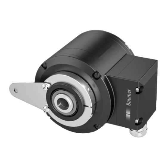
Baumer HUBNER BERLIN HMG 10 Montage- Und Betriebsanleitung
Devicenet absoluter drehgeber mit magnetischer abtastung
Vorschau ausblenden
Andere Handbücher für HUBNER BERLIN HMG 10:
- Montage- und betriebsanleitung (72 Seiten) ,
- Betriebsanleitung (52 Seiten) ,
- Handbuch (51 Seiten)
Inhaltsverzeichnis
Verfügbare Sprachen
Verfügbare Sprachen
Quicklinks
Inhaltsverzeichnis

Verwandte Anleitungen für Baumer HUBNER BERLIN HMG 10


Inhaltszusammenfassung für Baumer HUBNER BERLIN HMG 10
- Seite 1 Montage- und Betriebsanleitung HMG 10 - DeviceNet Absoluter Drehgeber mit magnetischer Abtastung...
-
Seite 2: Inhaltsverzeichnis
INHALTSVERZEICHNIS INHALTSVERZEICHNIS 1. WICHTIGE HINWEISE �����������������������������������������������������������������������������������������������������������1 1�1 Symbolerklärung �������������������������������������������������������������������������������������������������������������1 1�2 Bestimmungsgemäße Verwendung ��������������������������������������������������������������������������������1 1�3 Haftungsausschluss �������������������������������������������������������������������������������������������������������1 1�4 Wartung und Lebensdauer ���������������������������������������������������������������������������������������������2 1�5 Zulassungen und Gewährleistung ����������������������������������������������������������������������������������2 1�6 Lagertemperatur und Entsorgung �����������������������������������������������������������������������������������2 2. SICHERHEITS- UND ACHTUNGSHINWEISE ����������������������������������������������������������������������3 2�1 Sicherheitshinweise ��������������������������������������������������������������������������������������������������������3 2�2 Achtungshinweise zu Montage und Betrieb �������������������������������������������������������������������4 3. - Seite 3 INHALTSVERZEICHNIS 5�1�6 Einstellung der Teilnehmeradresse ��������������������������������������������������������������������16 5�1�7 Einstellung der Übertragungsrate �����������������������������������������������������������������������17 5�2 Drehzahlschalter und Zusatzausgang inkremental ������������������������������������������������������17 5�2�1 Beschreibung der Anschlüsse ����������������������������������������������������������������������������17 5�2�2 Ausgangssignale inkremental (Zusatzausgang) ������������������������������������������������18 5�2�3 LED-Funktionsanzeigen �������������������������������������������������������������������������������������18 5�2�4 Drehzahlschalter - Ausgangsschaltverhalten �����������������������������������������������������19 5�2�5 Kabelanschluss ��������������������������������������������������������������������������������������������������20 5�2�6 Belegung Anschlussklemmen ����������������������������������������������������������������������������21 5�2�6�1 Anschlussklemmen Klemmenkasten [B] Drehzahlschalter ohne Zusatzausgang ������������������������������������������������21 5�2�6�2 Anschlussklemmen Klemmenkasten [B]...
-
Seite 4: Wichtige Hinweise
WICHTIGE HINWEISE WICHTIGE HINWEISE Symbolerklärung Warnung Schwere Verletzungen bis hin zum Tod sowie Sachschäden sind die Folge bei Missachtung Achtung Missachtung kann Sachschäden und Zerstörung/Fehlfunktion des Drehgebers verursachen Information Zusatzinformationen und Empfehlungen Bestimmungsgemäße Verwendung Der Drehgeber ist ein Präzisionsmessgerät� Er dient der Drehzahl- /Positionserfassung zur Steuerung von Antrieben und Bereitstellung von Messwerten als elektrische Ausgangssig- nale für das Folgegerät�... -
Seite 5: 1�4 Wartung Und Lebensdauer
WICHTIGE HINWEISE Wartung und Lebensdauer Der Drehgeber darf für Montage- und Wartungsarbeiten nur wie in dieser Anleitung be- schrieben geöffnet werden� Reparaturen oder Wartungsarbeiten, die ein vollständiges Öff- nen des Drehgebers erfordern, sind ausschließlich vom Hersteller durchzuführen� Am Drehgeber dürfen keine Veränderungen vorgenommen werden� Die zu erwartende Lebensdauer des Drehgebers hängt von den Kugellagern ab, die mit einer Dauerschmierung ausgestattet sind�... -
Seite 6: Sicherheits- Und Achtungshinweise
SICHERHEITS- UND ACHTUNGSHINWEISE SICHERHEITS- UND ACHTUNGSHINWEISE Sicherheitshinweise Explosionsgefahr Durch Funkenbildung kann ein Brand und eine Explosion ausgelöst werden� » Den Drehgeber nicht in Bereichen mit explosionsgefährdeten bzw� leicht entzündli- chen Materialien verwenden� Durch eventuelle Funkenbildung können diese leicht Feuer fangen und/oder explodieren� Verletzungsgefahr durch rotierende Wellen Haare und Kleidungsstücke können von rotierenden Wellen erfasst werden�... -
Seite 7: 2�2 Achtungshinweise Zu Montage Und Betrieb
SICHERHEITS- UND ACHTUNGSHINWEISE Achtungshinweise zu Montage und Betrieb Zerstörungsgefahr durch elektrostatische Aufladung Die elektronischen Bauteile im Drehgeber sind empfindlich gegen hohe Spannun- gen� » Steckkontakte und elektronische Komponenten nicht berühren� » Ausgangsklemmen vor Fremdspannungen schützen� » Maximale Betriebsspannung nicht überschreiten� Zerstörungsgefahr durch mechanische Überlastung Eine starre Befestigung kann zu Überlastung durch Zwangskräfte führen�... -
Seite 8: Vorbereitung
VoRBEREITUNG VORBEREITUNG Lieferumfang 6d 6e 6f 7a 6a 6b [ B ] [ A ] [ A ] Gehäuse Einseitig offene Hohlwelle* oder Konuswelle*: Abdeckung Einseitig offene Hohlwelle oder Konus- welle mit Schlüsselfläche SW 17 mm Kombi-Torx-Schraube - DIN 7964, M4x10 mm 7b Spannelement, nicht bei Konuswelle LED-Funktionsanzeigen... -
Seite 9: 3�2 Zur Montage/Demontage Erforderliches Zubehör (Nicht Im Lieferumfang Enthalten)
VoRBEREITUNG Zur Montage/Demontage erforderliches Zubehör (nicht im Lieferumfang enthalten) Für den elektrischen Anschluss sind noch Anschlusskabel und ggf� Stecker erforder- lich� Details siehe Abschnitt 5, Seite 13� Drehmomentstütze, Länge L / Bestellnummer Standardversion: 67-70 mm / 11043628 125 (±5) mm, kürzbar auf ≥71 mm / 11004078 440 (+20/-15) mm, kürzbar auf ≥131 mm / 11002915 Isolierte Version: 67-70 mm / 11054917... -
Seite 10: Montage
MoNTAGE / PoSITIoNSEINSTELLUNG DES DREHMoMENTBLECHES MONTAGE Positionseinstellung des Drehmomentbleches TX 20 Schraube lösen 360° Schraube festziehen Mt = 2-3 Nm Montage der Drehmomentstütze am Drehgeber » Anbauhinweise zur Drehmomentstütze in Abschnitt 4.4, Seite 11 beachten� 10 mm 10 mm 7/33 MB252DE - 11173967, 16A1, Baumer_HMG10-DeviceNet_II_DE... -
Seite 11: 4�3 Montage An Antriebswelle
MoNTAGE / MoNTAGE AN ANTRIEBSWELLE Montage an Antriebswelle 4.3.1 Version mit einseitig offener Hohlwelle Lebensdauereinschränkung und Winkelfehler durch Rundlauffehler Hohe Rundlauffehler der Antriebswelle verursachen Winkelfehler des Drehge- bers, siehe Abschnitt 4.5, Seite 12� Hohe Rundlauffehler der Antriebswelle verursachen Vibrationen, die die Lebens- dauer des Drehgebers verkürzen können�... -
Seite 12: 4�3�2 Version Mit Konuswelle
MoNTAGE / MoNTAGE AN ANTRIEBSWELLE 4.3.2 Version mit Konuswelle Lebensdauereinschränkung und Winkelfehler durch Rundlauffehler Hohe Rundlauffehler der Antriebswelle verursachen Winkelfehler des Drehge- bers, siehe Abschnitt 4.5, Seite 12� Hohe Rundlauffehler der Antriebswelle verursachen Vibrationen, die die Lebens- dauer des Drehgebers verkürzen können� »... -
Seite 13: 4�3�3 Version Mit Durchgehender Hohlwelle
MoNTAGE / MoNTAGE AN ANTRIEBSWELLE 4.3.3 Version mit durchgehender Hohlwelle Lebensdauereinschränkung und Winkelfehler des Drehgebers Hohe Rundlauffehler der Antriebswelle verursachen Winkelfehler des Drehge- bers, siehe Abschnitt 4.5, Seite 12� Hohe Rundlauffehler der Antriebswelle verursachen Vibrationen, die die Lebens- dauer des Drehgebers verkürzen können� »... -
Seite 14: Montage / Antriebsseitige Montage Der Drehmomentstütze
MoNTAGE / ANTRIEBSSEITIGE MoNTAGE DER DREHMoMENTSTÜTZE Antriebsseitige Montage der Drehmomentstütze Lebensdauereinschränkung und Winkelfehler des Drehgebers Ein Spiel der Drehmomentstütze von beispielsweise ±0,03 mm entspricht einem Rundlauffehler des Drehgebers von 0,06 mm, was zu einem großen Winkelfehler führen kann, siehe Abschnitt 4.5, Seite 12�... -
Seite 15: Montage / Hinweis Zur Vermeidung Von Winkelfehlern
MoNTAGE / HINWEIS ZUR VERMEIDUNG VoN WINKELFEHLERN Hinweis zur Vermeidung von Winkelfehlern Für einen einwandfreien Betrieb des Drehgebers ist ein korrekter Anbau, insbesondere der Drehmomentstütze, notwendig, wie in Abschnitt 4�1 bis 4�4 beschrieben� Die Rundlaufabweichung der Motorwelle sollte nicht mehr als 0,2 mm (0,03 mm empfoh- len) betragen, da hierdurch Winkelfehler verursacht werden�... -
Seite 16: Elektrischer Anschluss / Devicenet
ELEKTRISCHER ANSCHLUSS / DEVICENET ELEKTRISCHER ANSCHLUSS DeviceNet Eine ausführliche Anleitung für die DeviceNet Schnittstelle und die EDS-Datei finden Sie im Handbuch auf der mit dem Gerät mitgelieferten CD� 5.1.1 Merkmale Bus-Protokoll DeviceNet Geräteprofil Device Profil for Encoders V 1.0 Betriebsarten I/o-Polling Cyclic Change of State... -
Seite 17: 5�1�2 Kabelanschluss Bei Version Mit Kabelverschraubungen
ELEKTRISCHER ANSCHLUSS / DEVICENET 5.1.2 Kabelanschluss bei Version mit Kabelverschraubungen Zur Gewährleistung der angegebenen Schutzart sind nur geeignete Kabeldurch- messer zu verwenden� Anschlusskabel sind nicht im Lieferumfang enthalten� TX 20 14 12 Busanschlusskasten DeviceNet Kombi-Torx-Schraube, M4x32 mm Scheibe A4, DIN 137 Stecker D-SUB Kabelverschraubung M16x1,5 mm... -
Seite 18: 5�1�3 Busanschlusskasten Devicenet [ A ] - Version Mit Stecker
ELEKTRISCHER ANSCHLUSS / DEVICENET Busanschlusskasten DeviceNet [ A ] - Version mit Stecker 5.1.3 Busanschlusskasten DeviceNet [ A ] [ C ] [ D ] 5.1.3.1 Stecker M12 [C] (Stift, 5-polig, A-codiert) STIFT ANSCHLUSS BESCHREIBUNG DRAIN Schirmanschluss Betriebsspannung 10���30 VDC Masseanschluss für UB CAN_H CAN Bus Signal (dominant HIGH) -
Seite 19: 5�1�4 Ansicht In Busanschlusskasten Devicenet [A]
ELEKTRISCHER ANSCHLUSS / DEVICENET 5.1.4 Ansicht in Busanschlusskasten DeviceNet [A] Einstellung der Abschlusswiderstände Einstellung der Übertragungsrate Einstellung der Teilnehmeradresse Klemmenbelegung DRAIN Schirmanschluss Masseanschluss für UB Betriebsspannung 10���30 VDC CAN_H CAN Bus Signal (dominant HIGH) CAN_L CAN Bus Signal (dominant LoW) Anschlüsse mit gleicher Bezeichnung sind intern verbunden und funktionsiden- tisch�... -
Seite 20: Elektrischer Anschluss / Drehzahlschalter Und Zusatzausgang Inkremental
ELEKTRISCHER ANSCHLUSS / DREHZAHLSCHALTER UND ZUSATZAUSGANG INKREMENTAL 5.1.7 Einstellung der Übertragungsrate ÜBERTRAGUNGSRATE EINSTELLUNG DIP-SCHALTER 125 kBaud (Werkseinstellung) 250 kBaud 500 kBaud 125 kBaud X = ohne Funktion Drehzahlschalter und Zusatzausgang inkremental 5.2.1 Beschreibung der Anschlüsse Betriebsspannung Masseanschluss Kanal A+ Kanal A _ (Kanal A+ invertiert) Kanal B+ Kanal B _ (Kanal B+ invertiert) Nullimpuls (Referenzsignal) -
Seite 21: 5�2�2 Ausgangssignale Inkremental (Zusatzausgang)
ELEKTRISCHER ANSCHLUSS / DREHZAHLSCHALTER UND ZUSATZAUSGANG INKREMENTAL 5.2.2 Ausgangssignale inkremental (Zusatzausgang) Bei positiver Drehrichtung 90° Nullimpuls+ Nullimpuls- 5.2.3 LED-Funktionsanzeigen Grün INC1 ohne Funktion ohne Funktion INC2 Unterspannung (Zusatzausgang Überlast inkremental) Übertemperatur Status Interner Fehler Speed Drehzahl über Schaltdrehzahl Drehzahl unter Schaltdrehzahl (Überdrehzahl) 18/33 MB252DE - 11173967, 16A1, Baumer_HMG10-DeviceNet_II_DE... -
Seite 22: 5�2�4 Drehzahlschalter - Ausgangsschaltverhalten
ELEKTRISCHER ANSCHLUSS / DREHZAHLSCHALTER UND ZUSATZAUSGANG INKREMENTAL 5.2.4 Drehzahlschalter - Ausgangsschaltverhalten Ereignis Zustand des Drehzahlschalterausgangs Während der Initialisierung Hochohmig (Überdrehzahl) Nach der Initialisierung und Drehzahl ≤ -ns (off) Hochohmig (Überdrehzahl) -ns (off) < Drehzahl ≤ -ns (on) Zustand unverändert Dreht sich der Geber während der Initialisierung innerhalb dieses Drehzahlbereichs, gilt nach der Initialisierung: Niederohmig (Keine Überdrehzahl) -ns (on) <... -
Seite 23: Kabelanschluss
ELEKTRISCHER ANSCHLUSS / DREHZAHLSCHALTER UND ZUSATZAUSGANG INKREMENTAL 5.2.5 Kabelanschluss Zur Gewährleistung der angegebenen Schutzart sind nur geeignete Kabeldurch- messer zu verwenden� Anschlusskabel sind nicht im Lieferumfang enthalten� Mt = 2-3 Nm TX 20 Klemmenkastendeckel Kombi-Torx-Schraube, M4x32 mm Kabelverschraubung Kabelschirm M20x1,5 mm für Kabel ø5-13 mm Anschlussklemmen Aderquerschnitt ≤1,5 mm... -
Seite 24: 5�2�6 Belegung Anschlussklemmen
ELEKTRISCHER ANSCHLUSS / DREHZAHLSCHALTER UND ZUSATZAUSGANG INKREMENTAL 5.2.6 Belegung Anschlussklemmen Betriebsspannung nicht auf die Ausgänge legen! Zerstörungsgefahr! Spannungsabfälle in langen Leitungen berücksichtigen (Ein- und Ausgänge)! 5.2.6.1 Anschlussklemmen Klemmenkasten [B] Drehzahlschalter ohne Zusatzausgang SP+* SP-* 5.2.6.2 Anschlussklemmen Klemmenkasten [B] Drehzahlschalter mit Zusatzausgang SP+* SP-* nE _... -
Seite 25: Abmessungen
ABMESSUNGEN / EINSEITIG oFFENE HoHLWELLE ABMESSUNGEN Einseitig offene Hohlwelle Drehzahlschalter DeviceNet [ A ] Zusatzausgang ød 53 65�5 [ B ] Positive Zubehör Drehrichtung [ C ] [ D ] Alle Maßangaben in Millimeter, wenn nicht anders angegeben� 22/33 MB252DE - 11173967, 16A1, Baumer_HMG10-DeviceNet_II_DE... -
Seite 26: 6�2 Durchgehende Hohlwelle
ABMESSUNGEN / DURCHGEHENDE HoHLWELLE Durchgehende Hohlwelle Drehzahlschalter DeviceNet [ A ] Zusatzausgang ød = 16 , 20 [ B ] Positive Zubehör Drehrichtung [ C ] [ D ] Alle Maßangaben in Millimeter, wenn nicht anders angegeben� 23/33 MB252DE - 11173967, 16A1, Baumer_HMG10-DeviceNet_II_DE... - Seite 27 ABMESSUNGEN / KoNUSWELLE Konuswelle Drehzahlschalter DeviceNet [ A ] Zusatzausgang [ B ] Positive Zubehör Drehrichtung [ C ] [ D ] Alle Maßangaben in Millimeter, wenn nicht anders angegeben� 24/33 MB252DE - 11173967, 16A1, Baumer_HMG10-DeviceNet_II_DE...
-
Seite 28: Demontage
DEMoNTAGE / VERSIoN MIT EINSEITIG oFFENER HoHLWELLE oDER KoNUSWELLE DEMONTAGE Version mit einseitig offener Hohlwelle oder Konuswelle Die Beispielbilder zeigen die Version mit einseitig offener Hohlwelle� Die Demontageschrit- te bei der Version mit Konuswelle sind identisch� 7.1.1 Schritt 1 17 mm 5 mm TX 20 10b 10c... - Seite 29 DEMoNTAGE / VERSIoN MIT EINSEITIG oFFENER HoHLWELLE oDER KoNUSWELLE 7.1.3 Schritt 3 17 mm 6 mm 7.1.4 Schritt 4 26/33 MB252DE - 11173967, 16A1, Baumer_HMG10-DeviceNet_II_DE...
-
Seite 30: Demontage / Version Mit Durchgehender Hohlwelle
DEMoNTAGE / VERSIoN MIT DURCHGEHENDER HoHLWELLE Version mit durchgehender Hohlwelle TX 10 Schraube lösen 1,6x8 mm 10 mm 27/33 MB252DE - 11173967, 16A1, Baumer_HMG10-DeviceNet_II_DE... -
Seite 31: Technische Daten
TECHNISCHE DATEN TECHNISCHE DATEN Technische Daten - elektrisch Betriebsspannung 10���30 VDC Kurzschlussfest Betriebsstrom ohne Last ≤200 mA Initialisierungszeit ≤500 ms nach Einschalten Schnittstelle DeviceNet Funktion Multiturn Übertragungsrate 125���500 kBaud Teilnehmeradresse Drehschalter in Busanschlusskasten (typenbezogen) Schrittzahl je Umdrehung 8192 / 13 Bit Anzahl der Umdrehungen 65536 / 16 Bit Zusatzausgänge... -
Seite 32: Technische Daten - Mechanisch
TECHNISCHE DATEN Technische Daten - mechanisch Baugrösse (Flansch) ø105 mm Flansch Drehmomentblech, 360° frei positionierbar Schutzart DIN EN 60529 IP 66/IP 67 Betriebsdrehzahl ≤6000 U/min Schaltdrehzahlbereich ±2���6000 U/min, Werkseinstellung 6000 U/min Betriebsdrehmoment typ� 10 Ncm Trägheitsmoment Rotor 950 gcm Zulässige Wellenbelastung ≤450 N axial ≤650 N radial Werkstoffe... - Seite 33 MB252DE - 11173967, 16A1, Baumer_HMG10-DeviceNet_II_DE...
- Seite 34 MB252DE - 11173967, 16A1, Baumer_HMG10-DeviceNet_II_DE...
- Seite 35 MB252DE - 11173967, 16A1, Baumer_HMG10-DeviceNet_II_DE...
- Seite 36 Baumer Hübner GmbH P.O. Box 12 69 43 · 10609 Berlin, Germany Phone: +49 (0)30/69003-0 · Fax: +49 (0)30/69003-104 info@baumerhuebner.com · www.baumer.com/motion MB252DE - 11173967, 16A1 (02�08�2016), Baumer_HMG10-DeviceNet_II_DE...
- Seite 69 MB252EN - 11173969, 16A1, Baumer_HMG10-DeviceNet_II_EN...
- Seite 70 MB252EN - 11173969, 16A1, Baumer_HMG10-DeviceNet_II_EN...
- Seite 71 MB252EN - 11173969, 16A1, Baumer_HMG10-DeviceNet_II_EN...