
Verwandte Anleitungen für Honeywell MB-Secure 4G


Inhaltszusammenfassung für Honeywell MB-Secure 4G
- Seite 1 Montage-Anschluss-Anleitung MB-Secure 4G IP USB Erweiterungsmodul Art.-Nr. 057810 MB-Secure IP USB Kommunikationsmodul Art.-Nr. 057820 800-23827 Rev. B Änderungen vorbehalten 2021-03-17...
- Seite 2 Montage-Anschluss-Anleitung / MB-Secure 4G IP USB / IP USB Erweiterungsmodul Sprachen MB-Secure 4G IP USB / IP USB Erweiterungsmodul...... 3 MB-Secure 4G IP USB / IP USB Extension Module...... 31...
-
Seite 3: Inhaltsverzeichnis
Montage-Anschluss-Anleitung / MB-Secure 4G IP USB / IP USB Erweiterungsmodul Inhaltsverzeichnis Sicherheitshinweise....................Allgemeines......................Anwendung..................... Leistungsmerkmale................. Unterstützte Geräte................Platinenaufbau - Übersicht.................. Platinenaufbau - Übersicht..............Verwendung der Anschlussklemmen............. LED USB....................Ethernet-Anschlusskabeltyp..............LED Anzeigen an der Ethernetbuchse........... Montage........................Einbau MB-Secure IP USB Kommunikationsmodul....... -
Seite 4: Sicherheitshinweise
Montage-Anschluss-Anleitung / MB-Secure 4G IP USB / IP USB Erweiterungsmodul Sicherheitshinweise Lesen Sie die Anleitung sorgfältig und vollständig durch, bevor Sie das Gerät installieren und in Betrieb nehmen. Sie erhalten wichtige Hinweise zur Montage, Programmierung und Bedienung. Das Gerät ist nach dem neuesten Stand der Technik gebaut. Benutzen Sie das Gerät nur: –... -
Seite 5: Unterstützte Geräte
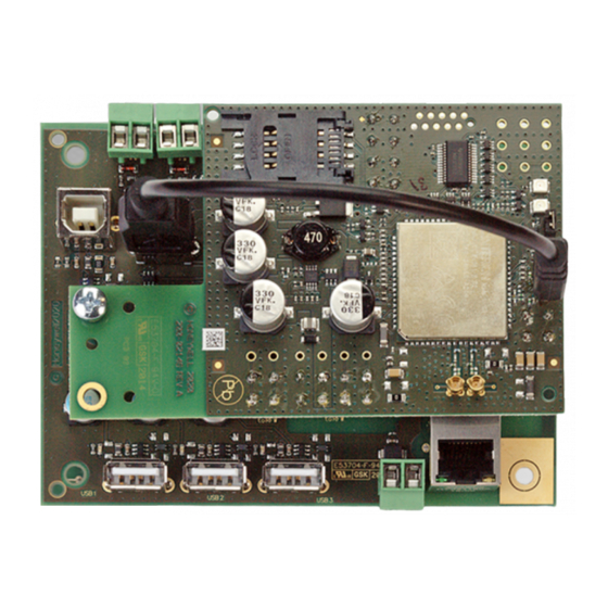
Montage-Anschluss-Anleitung / MB-Secure 4G IP USB / IP USB Erweiterungsmodul Unterstützte Geräte Das MB-Secure IP USB Kommunikationsmodul wird von folgendem Gerät unterstützt: MB-Secure ab Firmwareversion V10.xx, in Verbindung mit IQ PanelControl ab V10.xx. Platinenaufbau - Übersicht Platinenaufbau - Übersicht Erdungsbrücken USB 4 (für 4G Übertragungs-... -
Seite 6: Ethernet-Anschlusskabeltyp
Montage-Anschluss-Anleitung / MB-Secure 4G IP USB / IP USB Erweiterungsmodul Ethernet-Anschlusskabeltyp Es muss der Kabeltyp Ethernet 10/100BASE-T Twisted Pair, Kategorie 5 oder höherwertig verwendet werden. Handelsbezeichnung z.B. CB-SUTP-3; Cat.5 E, FTP; Cat. 5 E, SFTP. SUTP = Screened Unshielded Twisted Pair. -
Seite 7: Anschluss Mb-Secure Ip Usb Kommunikationsmodul
Montage-Anschluss-Anleitung / MB-Secure 4G IP USB / IP USB Erweiterungsmodul Die Platine wird auf einen vorgesehenen freien Montageplatz im Zentralengehäuse (Bezeich- net als Option) der Einbruchmelderzentrale montiert (siehe Errichteranleitung der Einbruch- melderzentrale). Zur Verwendung kommen die geeigneten Zentralengehäuse ZG20, ZG3.1 oder ZG4. - Seite 8 Montage-Anschluss-Anleitung / MB-Secure 4G IP USB / IP USB Erweiterungsmodul Der Anschluss an die Zentrale MB-Secure erfolgt über die USB-Masterbuchse auf der Rechnerplatine der MB-Secure. Verwenden für Anschluss nur das den Kommu- nikationsmodulen beiliegende spezielle USB-Verbindungska- bel. Dieses Verbindungskabel besitzt eine zusätzlich, heraus- geführte Anschlussleitung für...
-
Seite 9: Versorgungsspannung
Montage-Anschluss-Anleitung / MB-Secure 4G IP USB / IP USB Erweiterungsmodul Versorgungsspannung Versorgungsspannung anschließen Versorgungsspannung an der Anschlussklemme (U 1) des Netzteils Art.-Nr. 013960 anschlie- ßen. Auf polrichtigen Anschluss achten! Das MB-Secure IP USB Kommunikationsmodul muss grundsätzlich über die Anschlussklemme mit Spannung versorgt werden. Eine Spannungsversorgung über USB ist nicht zulässig,... -
Seite 10: Technische Daten
Montage-Anschluss-Anleitung / MB-Secure 4G IP USB / IP USB Erweiterungsmodul Technische Daten Technische Daten USB-HUB Betriebsnennspannung 12 V DC Betriebsspannungsbereich 10,5 V DC bis 15 V DC Stromaufnahme bei Nennspannung die Gesamtstromaufnahme (alle USB Anschlüsse plus Modul) darf 990 mA nicht übersteigen. -
Seite 11: Übertragungsgerät 4G Ip-Modul
Bei Einbruchmeldeanlagen (EMA) der Sicherheitsklassen A, B und C stellt der VdS hinsichtlich der Fernalarmierung erhöhte Anforderungen an die Verfügbarkeit der Übertragungswege. Das MB-Secure 4G IP USB Erweiterungsmodul beinhaltet alle Leistungsmerkmale des IP USB Kommunikationsmoduls, zusätzlich ist ein 4G Übertragungsmodul integriert. In Verbindung mit der entsprechenden MB-Secure Lizenzoption ist die Aufschaltung/Kommunikation zu Leitstellen, SMS bzw. -
Seite 12: Gsm-Gprs-Umts-Lte Übertragung
Montage-Anschluss-Anleitung / MB-Secure 4G IP USB / IP USB Erweiterungsmodul 6.1.2.3 GSM-GPRS-UMTS-LTE Übertragung Mit dem 4G IP USB Erweiterungsmodul (Art.-Nr. 057810) und der Zentrale MB-Secure ist es mög- lich mittels Hilfe des GSM Dienstes GPRS (General Packet Radio Service), UMTS (Universal Mobile Telecommunications System) und LTE (Long Term Evolution) in das Internet einwählen. -
Seite 13: Konfigurationsbeispiel Als Redundanter Übertragungsweg
Montage-Anschluss-Anleitung / MB-Secure 4G IP USB / IP USB Erweiterungsmodul 6.1.2.5 Konfigurationsbeispiel als redundanter Übertragungsweg GSM-Netz All-IP Ethernet (TCP/IP) Wachunternehmen MB-Secure 4G IP USB Erweiterungsmodul leitungsgebundenes Netz Router Die Grafik zeigt die grundsätzliche Möglichkeit der Aufschaltung auf eine Empfangseinrichtung eines Wachunternehmens. -
Seite 14: Übertragungssystem Und Übertragungswege
Montage-Anschluss-Anleitung / MB-Secure 4G IP USB / IP USB Erweiterungsmodul 6.1.2.7 Übertragungssystem und Übertragungswege Das 4G IP USB Erweiterungsmodul (Art.-Nr. 057810) beinhaltet ein 4G Übetragungsmodem und ist als Aufsteckplatine ausgeführt. Das 4G IP USB Erweiterungsmodul muss in das entsprechende Systemgehäuse der Zentrale MB-Secure integriert werden. Im Lieferumfang enthalten sind 2 GSM- Antennen, welche zur universellen Montage an den Honeywell ZG-Gehäusetypen geeignet sind. -
Seite 15: Hinweise Zum Mobilfunk Kartenvertrag
Montage-Anschluss-Anleitung / MB-Secure 4G IP USB / IP USB Erweiterungsmodul 6.1.3 Hinweise zum Mobilfunk Kartenvertrag Für den Betrieb des 4G IP USB Erweiterungsmodul (Art.-Nr. 057810) ist ein Mobil- funk Kartenvertrag erforderlich. Dieser Kartenvertrag ist nicht Bestandteil des Kom- plettpaketes. Für den Betreiber des 4G IP USB Erweiterungsmodul besteht daher die Möglichkeit, einen kundenspezifischen Tarif, bei einem Händler seiner Wahl... -
Seite 16: Übersicht 4G Ip-Modul
Main-(Haupt)-Antennenanschluss 6.2.2 Montageübersicht Die Abbildung zeigt das MB-Secure 4G IP USB Erweiterungsmodul kompett mit aufgesetztem 4G Übertragungsmodul. Das 4G Übertragungsmodul muss an der gezeigten Position auf die Platine des IP USB-Kommunikationsmoduls aufgesteckt werden. Achten Sie auf einen korrekten Sitz aller... - Seite 17 Montage-Anschluss-Anleitung / MB-Secure 4G IP USB / IP USB Erweiterungsmodul Montieren Sie zuerst den Montagebolzen (liegt im Zubehörbeutel bei), am IP USB- Kommunikationsmodul (Position im Bild gezeigt). Stecken Sie anschließend das 4G Übertragungsmodul auf das IP USB-Kommunikationsmodul und fixieren Sie mit der beiliegenden Schraube das Modul am Bolzen.
-
Seite 18: Antennenmontage
Montage-Anschluss-Anleitung / MB-Secure 4G IP USB / IP USB Erweiterungsmodul 6.2.3 Antennenmontage Dem RFW-4000 GSM/GPRS/4G liegen zwei GSM-Antennen mit Kabel und Stecker bei. Kabellänge der beiliegenden Antenne 50 In Bezug auf den GSM Netzzugang besteht die Möglichkeit 1 oder 2 Antennen zu verwen-... -
Seite 19: Antennenmontage Bei Gehäusen Mit Montagewinkel
Montage-Anschluss-Anleitung / MB-Secure 4G IP USB / IP USB Erweiterungsmodul 6.2.3.1 Antennenmontage bei Gehäusen mit Montagewinkel Bei Gehäusen die mit Montagewinkel an der Wand befestigt wer- den, wie zum Beispiel das Gehäuse ZG2 ist die Vorgehens- weise wie folgt: Vor der Gehäusemontage an der Wand beachten: Beide Antennenkabel an der Rückseite des Gehäuses verlegen. -
Seite 20: Fixierung Des Antennenkabels
Montage-Anschluss-Anleitung / MB-Secure 4G IP USB / IP USB Erweiterungsmodul Vor der Montage: in den Gehäuseboden die beiden beilie- genden Distanzbolzen einschrauben. Den Gehäuseboden in die Einhängeleiste einhängen, gleichzeitig das Antennenkabel in das Gehäuse einführen. Das Gehäuse mit den Befestigungsschrauben gegen Aus- hängen sichern. -
Seite 21: Hinweis Zum Gsm Antennenanschluss
Montage-Anschluss-Anleitung / MB-Secure 4G IP USB / IP USB Erweiterungsmodul 6.2.4 Hinweis zum GSM Antennenanschluss Antennenkabel nur senkrecht ein-, bzw ausstecken. -
Seite 22: Hinweis Zur Leitungsverlegung In Gehäusen
Montage-Anschluss-Anleitung / MB-Secure 4G IP USB / IP USB Erweiterungsmodul 6.2.5 Hinweis zur Leitungsverlegung in Gehäusen Die Abbildung zeigt die Leitungsverlegung für das Übertragungssystem innerhalb eines Zentra- lengehäuses: Antenne Antenne Antennen- Anschlusskabel (Kabellänge 50 cm) Antennenkabel im innern MB-Secure 4G IP USB Erweiterungsmodul des Gehäuses so kurz... -
Seite 23: Hinweise Für Installation, Inbetriebnahme Und Sicherheit
Montage-Anschluss-Anleitung / MB-Secure 4G IP USB / IP USB Erweiterungsmodul Hinweise für Installation, Inbetriebnahme und Sicherheit Für einen ordnungsgemäßen Betrieb des 4G USB Erweiterungsmoduls müssen die nachfolgenden Hinweise unbedingt beachtet werden! Während der Projektierungsphase muss zunächst ermittelt werden, welches GSM-Netz im zu überwachenden Objekt zur Verfügung steht. -
Seite 24: Inbetriebnahme 4G Ip-Modul
Montage-Anschluss-Anleitung / MB-Secure 4G IP USB / IP USB Erweiterungsmodul Informationen für fest montierte Mobilfunk-Endgeräte Informationen für fest montierte Mobilfunk-Endgeräte - Für Mobilfunkgeräte, die fest mon- tiert sind und einen eigenen Netzanschluss haben, gelten diese zusätzliche Hinweise. Da die Messverfahren für den SAR-Wert nur für eine Nutzung nah am Kopf oder Körper angewen- det werden können, wird die Sicherheit bei fest montierten Mobilfunkgeräten durch Angabe... -
Seite 25: Antenne Und Antennenkabellängen
Montage-Anschluss-Anleitung / MB-Secure 4G IP USB / IP USB Erweiterungsmodul SIM Karte einsetzen Oberteil ca. 90° aufklappen, SIM Karte in die Führungen des Halters einsetzen. SIM card Seitenrichtige Position der SIM Karte beachten. Schliessen SIM Halter in Pfeilrichtung bis zum Einrasten leicht in Pfeilrichtung (LOOK) schieben. -
Seite 26: Verwendung Von Abgesetzten Antennen
Montage-Anschluss-Anleitung / MB-Secure 4G IP USB / IP USB Erweiterungsmodul Beim Absetzen der Antennen vom RFW ist darauf zu achten, dass die auftretende Signaldämpfung auf der Leitung mit berücksichtigt wird. Da dieser Dämpfungs- wert sehr stark vom verwendeten Kabel abhängig ist, können folgende Werte als Richtwerte angesehen werden. -
Seite 27: Hinweis Zur Auswahl Der Stromversorgung
Montage-Anschluss-Anleitung / MB-Secure 4G IP USB / IP USB Erweiterungsmodul 6.4.2.3 Montagebeispiel Kabeladapter Abgesetzte Antennen dürfen nur mit der Antennenadapterpla- tine und Montagewinkel verbaut werden. Diese wird an der Position der HUB-Montageschraube an dem USB-HUB fixiert. Der Anschluss des Antennensteckers (SMA) auf die Eingangs- buchse des GSM Terminals (MMCX) erfolgt mittels diesem Kabeladapter. -
Seite 28: Übertragung Und Funktion Testen
Montage-Anschluss-Anleitung / MB-Secure 4G IP USB / IP USB Erweiterungsmodul LED grün (2) LED grün -leuchtet: Versorgungsspannung liegt am RFW-4000 an. LED gelb (1) Die gelbe LED zeigt mittels unterschiedlichen Blink-, und Pausenzeiten den aktuellen Zustand des Moduls innerhalb des GSM-Netzes an:... -
Seite 29: Technische Daten
Montage-Anschluss-Anleitung / MB-Secure 4G IP USB / IP USB Erweiterungsmodul Technische Daten 6.5.1 Technische Daten 4G IP-Modul Betriebsnennspannung 12 V DC Betriebsspannungsbereich 10,5 V DC bis 15 V DC Stromaufnahme (max.) die Gesamtstromaufnahme (alle USB Anschlüsse plus 4G IP-Modul) darf 1190 mA nicht übersteigen. - Seite 30 Montage-Anschluss-Anleitung / MB-Secure 4G IP USB / IP USB Erweiterungsmodul CE Konformität MB Secure - 4G IP USB Erweiterungsmodul Hiermit erklärt die Novar GmbH, dass das Gerät Einbruchmeldezentrale MB Secure 0138xx mit der Option 4G IP USB Erweiterungsmodul Art.-Nr. 057810 der Richtlinie 2014/53/EU entspricht.
- Seite 31 Mounting and Connection Instructions MB-Secure 4G IP USB / IP USB Extension Module Contents Safety Instructions....................General Information....................Application....................Performance features................Supported devices.................. Circuit board structure - overview..............Circuit board structure - overview............Use of connection terminals..............LED USB....................Ethernet attachment cable..............
-
Seite 32: Safety Instructions
Mounting and Connection Instructions MB-Secure 4G IP USB / IP USB Extension Module Safety Instructions All of the instructions should be carefully read before you install and commission the device. You will find important information on here on the assembling, programming and operating procedures. -
Seite 33: Supported Devices
Mounting and Connection Instructions MB-Secure 4G IP USB / IP USB Extension Module Supported devices The MB-Secure IP USB communication module is supported by the following device: MB-Secure from firmware version V10.xx, in conjunction with IQ PanelControl from V10.xx. Circuit board structure - overview... -
Seite 34: Ethernet Attachment Cable
Mounting and Connection Instructions MB-Secure 4G IP USB / IP USB Extension Module Ethernet attachment cable An Ethernet-type10/100BASE-T Twisted Pair cable, category 5 or higher quality must be used. Trade name for example CB-SUTP-3; cat. 5 E; FTP; CV Cat. 5 E, SFTP. -
Seite 35: Connection Mb-Secure Ip Usb Communication Module
Mounting and Connection Instructions MB-Secure 4G IP USB / IP USB Extension Module The PCB is mounted on a designated free space provided in the panel housing (designated as "optional") of the intrusion alarm control panel (see the installation instructions for the intrusion alarm control panel). - Seite 36 Mounting and Connection Instructions MB-Secure 4G IP USB / IP USB Extension Module The connection to the MB-Secure control panel is made via the USB master socket on the MB- Secure processor board. Only use the special USB connection cable supplied with the communication modules for the connection.
-
Seite 37: Power Supply
Mounting and Connection Instructions MB-Secure 4G IP USB / IP USB Extension Module Power supply Connecting the power supply voltage Connect the supply voltage to the terminal (U 1) of the power supply unit art. no. 013960. Ensure that the polarity is correct! The MB-Secure IP USB communication module must always be supplied with power via the connection terminal. -
Seite 38: Technical Data
Mounting and Connection Instructions MB-Secure 4G IP USB / IP USB Extension Module Technical data Technical data USB-HUB Nominal operating voltage 12 V DC Operating voltage range 10.5 V DC to 15 V DC Power intake with nominal voltage The total power intake (all USB connections plus module) must not exceed 990 mA. -
Seite 39: Transmission Device 4G Ip Module
The MB-Secure 4G IP USB extension module includes all the features of the IP USB communi- cation module. Additionally, a 4G transmission module is integrated. In conjunction with the corre- sponding MB-Secure licence option, connection/communication to control centres, SMS or e-mail transmission is possible. - Seite 40 Mounting and Connection Instructions MB-Secure 4G IP USB / IP USB Extension Module 6.1.2.3 GSM-GPRS-UMTS-LTE transmission With the 4G IP USB extension module (art. no. 057810) and the MB-Secure control panel, it is pos- sible to dial into the Internet using the GSM service GPRS (General Packet Radio Service), UMTS (Universal Mobile Telecommunications System) and LTE (Long Term Evolution).
- Seite 41 Mounting and Connection Instructions MB-Secure 4G IP USB / IP USB Extension Module 6.1.2.5 Configuration example as redundant transmission path This graphic shows the basic option of connecting up to a receiver at a security company. 6.1.2.6 Configuration example GSM-GPRS transmission The graphic shows how to implement a standing or need-based IP connection to a receiving control panel.
-
Seite 42: Notes About Mobile Network Card Contract
Mounting and Connection Instructions MB-Secure 4G IP USB / IP USB Extension Module 6.1.2.7 Transmission system and transmission paths The 4G IP USB extension module (art. no. 057810) contains a 4G transmission modem and is designed as a plug-on PCB. The 4G IP USB extension module must be integrated into the corre- sponding system housing of the MB-Secure control panel. - Seite 43 Mounting and Connection Instructions MB-Secure 4G IP USB / IP USB Extension Module 6.1.3.1 Comments on applying for a mobile network card In general, an application to unlock a mobile network card can be made at any authorised specialist dealer.
-
Seite 44: Overview 4G Ip Module
Main antenna connection 6.2.2 Installation overview The illustration shows the MB-Secure 4G IP USB extension module complete with 4G transmission module attached. The 4G transmission module must be plugged onto the PCB of the IP USB communication module at the position shown. Ensure that all plug connections are seated correctly. - Seite 45 Mounting and Connection Instructions MB-Secure 4G IP USB / IP USB Extension Module First mount the mounting bolt (enclosed in the accessory bag), on the IP USB com- munication module (position shown in the picture). Then plug the 4G transmission module onto the IP USB communication module and fix the module to the bolt with the enclosed screw.
-
Seite 46: Antenna Installation
Mounting and Connection Instructions MB-Secure 4G IP USB / IP USB Extension Module 6.2.3 Antenna installation The RFW-4000 GSM/GPRS/4G is supplied with two GSM anten- nas with cable and connector. The cable length for the supplied antenna is 50 cm. - Seite 47 Mounting and Connection Instructions MB-Secure 4G IP USB / IP USB Extension Module 6.2.3.1 Antenna installation for housings with mounting bracket For housings mounted on the wall using a mounting bracket, such as the ZG2 housing the procedure is as follows:...
- Seite 48 Mounting and Connection Instructions MB-Secure 4G IP USB / IP USB Extension Module Before mounting: Screw both supplied spacer bolts into the bottom of the housing. Attach the bottom of the housing to the suspension rail, and at the same time insert the antenna cable into the housing.
-
Seite 49: Note On The Gsm Antenna Connection
Mounting and Connection Instructions MB-Secure 4G IP USB / IP USB Extension Module 6.2.4 Note on the GSM antenna connection Always insert/remove antenna cable in a vertical position. -
Seite 50: Note On Routing Of Wiring In Housings
Mounting and Connection Instructions MB-Secure 4G IP USB / IP USB Extension Module 6.2.5 Note on routing of wiring in housings This figure shows the routing of wiring for the transmission system inside a panel housing: To comply with the requirement of the Low-Voltage Directive, the supply line for the 230 V supply voltage for the power unit mustonly be routed inside the cross- hatched area. -
Seite 51: Notes On Installation, Commissioning And Safety
Mounting and Connection Instructions MB-Secure 4G IP USB / IP USB Extension Module Notes on installation, commissioning and safety For proper operation of the 4G USB extension module, the following instructions must be observed!. During the project planning phase, first establish which GSM network is available in the building under surveillance . -
Seite 52: Commissioning 4G Ip Module
Mounting and Connection Instructions MB-Secure 4G IP USB / IP USB Extension Module Information for permanently mounted wireless terminals Information for permanently mounted wireless terminal devices - the following additional noti- fications apply for wireless devices in a fixed location with their own power connection. Since... -
Seite 53: Antenna And Antenna Cable Lengths
Mounting and Connection Instructions MB-Secure 4G IP USB / IP USB Extension Module Insert SIM card Open the upper part approx. 90°, insert the SIM card into the guides of the holder. SIM card Ensure that the SIM card is in the correct position. - Seite 54 Mounting and Connection Instructions MB-Secure 4G IP USB / IP USB Extension Module When placing the antennas from the RFW, care must be taken to ensure that the signal attenuation occurring on the line is taken into account. Since this attenuation value very much depends on the cable used, the following values can be regarded as reference values.
-
Seite 55: Note On Selection Of The Power Supply
Mounting and Connection Instructions MB-Secure 4G IP USB / IP USB Extension Module 6.4.2.3 Sample installation for cable adapter Remote antennas may only be installed with the antenna adapter PCB and mounting bracket. The PCB is fixed to the position of the HUB mounting screw on the USB HUB. -
Seite 56: Test Transmission And Function
Mounting and Connection Instructions MB-Secure 4G IP USB / IP USB Extension Module LED green (2) LED green - lit: Supply voltage is present on the RFW-4000 . LED yellow (1) The yellow LED uses a range of different flashing and waiting times to display the current status... -
Seite 57: Technical Data 4G Ip Module
Mounting and Connection Instructions MB-Secure 4G IP USB / IP USB Extension Module Technical data 6.5.1 Technical data 4G IP module Nominal operating voltage 12 V DC Operating voltage range 10.5 V DC to 15 V DC Power intake (max.) The total power intake (all USB ports plus 4G IP module) must not exceed 1190 mA. - Seite 58 Mounting and Connection Instructions MB-Secure 4G IP USB / IP USB Extension Module CE Conformity MB Secure - 4G IP USB Extension Module Novar GmbH hereby declares that the intrusion alarm panel MB Secure 0138xx with the option 4G IP USB extension module art. no. 057810 complies with Direc- tive 2014/53/EU.
- Seite 59 Mounting and Connection Instructions MB-Secure 4G IP USB / IP USB Extension Module...
- Seite 60 Honeywell Commercial Security Novar GmbH Johannes-Mauthe-Straße 14 800-23827 Rev. B D-72458 Albstadt 2021-03-17 www.honeywell.com/security/de © 2021 Novar GmbH...