Werbung
Quicklinks
Installationsanleitung
IQ8MCP Elektronikmodul / IQ8MCP
Installation Instruction
IQ8MCP Electronic module / IQ8MCP
(Art.-Nr. / Part No. 804955 / 804956 / 804971)
Technische Änderungen vorbehalten!
798936
Technical changes reserved!
D
GB
07.2014 / AA
© 2014 Honeywell International Inc.
Novar GmbH a Honeywell Company
Dieselstraße 2, D-41469 Neuss
Internet:
www.esser-systems.com
E-Mail:
info@esser-systems.com
D
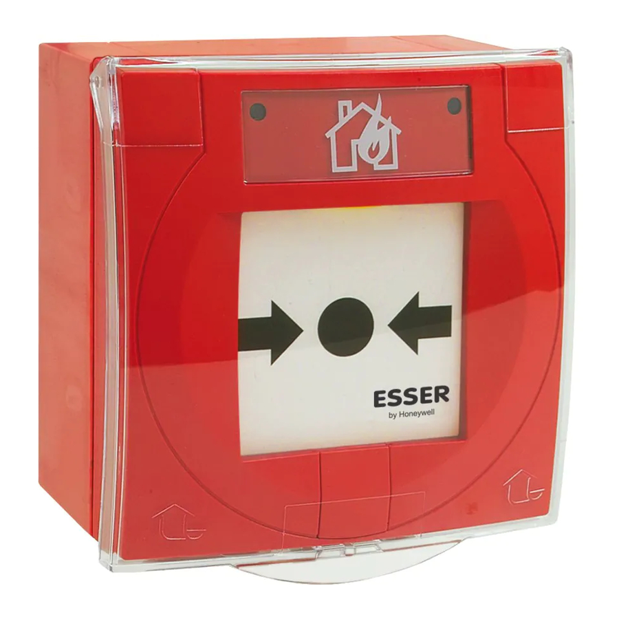
Bei dem Einsatz des Melders als Handfeuermelder muss zwingend ein
rotes Gehäuse und die normenkonforme Symbolik gemäß Abb. 3/4
verwendet werden. Andere Gehäusefarben und Beschriftungen gelten
nicht als Handfeuermelder, sondern als manuelle Auslösevorrichtung.
Verdrahtungsfolge der Ringleitung beachten!
Klemmen 1-4 IN (Eingang) OUT (Ausgang).
Fernmeldekabel I-Y (St) Y n x 2 x 0,8 mm mit besonderer Kenn-
zeichnung oder Brandmeldekabel verwenden!
Durch den Anschluss der Kabelabschirmung werden die Signal-
leitungen gegen Störeinflüsse geschützt.
Anschlusskabel im Melder, zum Schutz vor Feuchtigkeit mit
Abtropfschlaufe verlegen.
Bei Servicearbeiten an dem Hand(feuer)melder eine evtl.
vorhandene Alarmweiterleitung, wie zum Beispiel die unbeab-
sichtigte
Auslösung
einer
Übertragungseinrichtung
beachten.
Ergänzende und aktuelle Informationen
Die Produktangaben entsprechen dem Stand der Drucklegung
und können durch Produktänderungen, geänderte Normen /
Richtlinien ggf. von den hier genannten Informationen
abweichen.
Aktualisierte
Informationen,
Konformitätserklärungen
Instandhaltungsvorgaben siehe www.esser-systems.com.
Dokumentation der Brandmelderzentrale bzgl. Normen, lokalen
Anforderungen und Systemvoraussetzungen beachten!
esserbus
®
und essernet
®
sind in Deutschland eingetragene
Warenzeichen.
Handfeuermelder und automatische Brandmelder dürfen gemäß
§
den VdS-Richtlinien nicht auf einer gemeinsamen Meldergruppe
betrieben werden (max. 10 Handfeuermelder/Gruppe).
GB
When the MCP is used as a manual call point it must be installed
in a red housing with an identification label showing the
standardize-conformal symbol as shown in Fig. 3/4. When
housings with different colours and identification labels are used
the unit is classed as a manual activation device and not as a
manual call point.
Observe the correct wiring sequence for the loop!
Terminals 1-4 IN (Input) OUT (Output).
Use designated communication cable I-Y (St) Y n x 2 x 0.8 mm or
fire alarm cable!
Connection of the cable shield to the ground terminal protects the
signal cables against interference.
Install inlaying cable with a dripping bend to protect the device from
dampness.
The alarm activation and triggering of notifying systems e.g.
manned centre link (Master box) must be observed during any
Service of the MCP.
Additional and updated Informations
The product specification relate to the date of issue and may
differ due to modifications and/or amended Standards and
Regulations from the given informations.
For updated informations to commissioning and maintenance of
Fire alarm detectors refer to www.esser-systems.com
Observe technical manuals of the FACP to ensure compliance to
standards and local requirements of Systems features!
esserbus
®
and essernet
®
are registered trademarks in Germany.
§
Pursuant to the VdS guidelines MCPs and automatic fire detectors
must not be operated in a common detector zone (max. 10 MCP
per detector zone).
Achtung!
Diese Anleitung ist vor der Inbetriebnahme des Gerätes genau durchzulesen.
Bei Schäden die durch Nichtbeachtung der Installationsanleitung verursacht
werden, erlischt der Gewährleistungsanspruch. Für Folgeschäden, die daraus
resultieren, wird keine Haftung übernommen.
Sicherheitshinweise
Den Melder NICHT an einer 230 V AC Nennspannung und nur im
vorgesehenen Temperaturbereich betreiben.
Die Wartung und Reparatur des Melders darf nur durch eine Fachkraft
erfolgen, die mit den damit verbundenen Gefahren und Vorschriften
vertraut ist.
Die Veränderung oder ein Umbau des Melders ist nicht zulässig.
Allgemein
Das IQ8MCP Elektronikmodul (Art.-Nr. 804955 / 804956) bzw. der IQ8MCP
(Art.-Nr. 804971) im roten Gehäuse mit dem Symbol „brennendes Haus" wird
als Handfeuermelder zur manuellen Auslösung eines Brandalarmes bzw. einer
Gefahrenmeldung in trockenen, nicht explosionsgefährdeten Betriebsstätten
eingesetzt. Der Melder ist für andere Verwendungen auch in verschiedenen
Ausführungen, wie z.B. unterschiedlichen Gehäusefarben und verschieden
bedruckten Einlegern verfügbar (siehe Tabelle Seite 2). Die Betriebsbereitschaft
des Melders wird durch die blinkende grüne LED (H) angezeigt; (Abb. 4).
Bedienung
Auslösen:
Scheibe mittig eindrücken bis die gelbe mechanische Alarm-
anzeige (G) im oberen Fensterbereich sichtbar ist und die rote
LED (F) leuchtet (Abb. 4).
Rückstellen:
Zum Einstecken des Schlüssels (C) die Schlüssellochab-
deckung (A) hochschieben (Abb. 1).
Melder mit Glasscheibe
MCP öffnen Schlüssel (C) bis zum Endanschlag nach rechts (M)
drehen und gebrochene Glasscheibe entfernen (Abb. 5). Neue
Glasscheibe einsetzen, MCP schließen und durch Links-
drehung (N) des Schlüssels bis zum Endanschlag nach oben
drücken (Abb. 6).
Melder mit Kunststoffbedienfeld
Schlüssel (C) bis zum Endanschlag nach rechts (M) drehen
(Abb. 5). Kunststoffbedienfeld (L) mit einer Linksdrehung (N)
des Schlüssels bis zum Endanschlag wieder nach oben
drücken (Abb. 6).
Testbetrieb:
Bei geschlossenem MCP Schlüssel (C) nach rechts (M)
drehen bis sich die Scheibe senkt (Abb. 5) und die Auslösung
(F/G) angezeigt wird (Abb. 4). Zum Rückstellen nach dem
Test die Scheibe mit einer Linksdrehung (N) des Schlüssels
bis zum Endanschlag wieder nach oben drücken (Abb. 6).
MCP öffnen:
Schlüssel (C) mit den beiden Kunststoffzapfen in die Öffnungen
der Unterseite einstecken (Abb. 2) und Verriegelung aufdrücken.
Das Gehäuseoberteil leicht nach oben ankippen und von dem
Gehäuseunterteil abnehmen.
MCP Symbolik:
Bei offenem Gehäuse transparente Abdeckung (D/E) lösen
und entnehmen. Beschriftungsfeld von vorne einlegen,
ausrichten, Abdeckung lagerichtig einsetzen und andrücken
(Abb. 3).
MCP schließen: Entriegelung mit dem Schlüssel bis zum linken Endanschlag
(N) drehen (Abb. 6) Schlüssel abziehen. Gehäuseoberteil
leicht angekippt auf die oberen Vertiefungen des Unterteiles
aufsetzen und vorsichtig bis zum Einrasten zudrücken.
Rückseite der
Glasscheibe oder
Papiereinleger:
Zur Kennzeichnung nicht betriebsbereiter Melder (J/K).
Kunststoff-
Schlüssel bis zum rechten Endanschlag drehen (Abb. 5).
bedienfeld oder
Scheibe (J/L) lagerichtig in die Gehäusevertiefung einlegen
Glasscheibe:
und durch Linksdrehung des Schlüssels bis zum End-
anschlag nach oben drücken (Abb. 6).
Schutz-Kit::
Zum Schutz vor unabsichtlicher Auslösung und zur Erhöhung
Art.-Nr. 704965
der Schutzart von IP 43 auf IP 55 wird die Abdeckung (O) in
(Option)
die seitlichen Vertiefungen (P) des Gehäuseoberteils eingesetzt
und kann zusätzlich verplombt (B) werden Abb. 2. Dichtungen
und Kabelverschraubung 1-4 gem. Abb. 9 montieren.
Montage
Der Melder wird auf einer Standard-Schalterdose
unter Putz
(Ø 55 – 60 mm) montiert.
auf Putz
Der Melder inkl. Montagegehäuse (Option) oder mit Montage-
rahmen (Option) wird auf einer glatten, geeigneten Wandfläche,
z.B. mit Dübeln (S6) und 2 Schrauben (Länge 40 mm) befestigt
(Abb. 7/8).
Anschaltungen
Die Anschaltung der Melder erfolgt über die esserbus
Ringleitung der Brandmelderzentrale. Handfeuermelder müssen auf der Ring-
leitung in eigenen Meldergruppen zusammengefasst werden. Kabel nur
(AÜE)
innerhalb des Gehäuses abisolieren.
Die Anschaltung erfolgt über die Anschlussklemmen 1-4. Diese können zur
Vereinfachung der Installation abgezogen werden.
Die Abschirmungen der Anschlusskabel müssen mit einer Schraubklemme
untereinander verbunden werden. In dem Montagegehäuse steht dazu eine
integrierte Anschlussklemme zur Verfügung (Abb. 7).
Leitungstrenner und ext. Meldergruppe
und
Die Leitungstrenner gewährleisten die Funktionstüchtigkeit der Anlage, falls ein
Segment der Ringleitung durch Kurzschluss ausfällt. Bei einem Kurzschluss öffnen die
Leitungstrenner vor und hinter dem Kurzschluss und schalten den Teil der
Ringleitung zwischen den Leitungstrennern ab. Ein einfacher Drahtbruch
beeinträchtigt die Funktion der Ringleitung nicht.
An diesen IQ8MCP kann eine externe Meldergruppe mit maximal zehn Standard
Handfeuermeldern (interner Alarmwiderstand jeweils 1 KOhm) angeschlossen
werden. Bei einer Auslösung wird die Adresse und der programmierte Zusatztext
des IQ8MCP angezeigt, an dem die ext. Meldergruppe angeschlossen ist.
Leitungslänge max. 500 Meter! Den letzten Handfeuermelder mit einem 10 KOhm
Abschlusswiderstand beschalten. Wird keine ext. Meldergruppe angeschlossen,
den 10 KOhm Widerstand direkt an den Klemmen 7/8 anschalten (Abb. 10).
Melder mit Relais (Art.-Nr. 804956)
An den Klemmen 6/7/8 stehen potentialfreie Kontakte eines Wechslers NC/C
(Öffner) oder NO/C (Schließer) zur Verfügung (Abb. 10). Der Relaisausgang
wird mit dem Auslösen dieses Melders aktiviert. Der Relaisausgang kann in den
Kundendaten der Brandmelderzentrale als Steuergruppe programmiert werden.
Max. Kontaktbelastung : 30 V DC / 1A.
Technische Daten
Betriebsspannung
Ruhestrom
Alarmstrom
Melderzahl
Alarmanzeige
Betriebsanzeige
Anschlussklemmen
Anwendungstemperatur
Lagertemperatur
Schutzart
Gehäuse
Farbe
Gewicht
Maße-Gehäuse (B x H x T)
Maße mit Aufputzgehäuse
Spezifikation
VdS-Anerkennung
Leistungserklärung
D
Important!
These instructions must be studied carefully before commissioning the device. Any
damage caused by failure to observe the installation instructions voids the
warranty. Furthermore, no liability can be accepted for any consequential damage
arising from such failure.
Safety information
General
The IQ8MCP Electronic module (Part No. 804955 / 804956) respectively the
IQ8MCP (Part No. 804971) in the red housing identified with a "burning house"
symbol is designated for use as a call point for manually triggering fire alarms or
other hazard alarms in dry workplaces not subject to explosion hazards. The call
point is also available in other versions for other applications, for example in
housings with different colours and with a choice of different identification labels
(refer to table page 2). The operation mode is displayed via the flashing green LED
(H); (Fig. 4).
Operation
Trigger alarm:
Reset:
Test mode:
MCP opening:
MCP Symbolism: With the housing open, remove the transparent plastic cover
MCP closing:
Glass screen
rear side or
Paper inlay:
Plastic operating
panel or
glass screen:
Protection kit:
Part No. 704965
(Option)
Installation
Flush
mounting:
Surface
mounting:
Wiring
/ esserbus
-PLus
®
®
The MCP can be connected to the esserbus
control panel. Manual call points must be configured together in their own detector
zones. Only remove insulation from cable sections inside the housing.
For wiring use terminals 1-4. These terminals can be removed to simplify the
installation.
The cable shield of the connection cable must be interconnected by using a single
terminal block. The mounting box provides an integrated terminal for the shield
connection (Fig. 7).
Zone isolator and ext. detector zone
The zone isolators ensure that the system continues to function even if a segment
circuit fails due to a short circuit. When a short occurs the zone isolators before and
after the short open, disconnecting the section of the loop between the isolators.
Simple wire breaks do not affect the functionality of the loop circuit.
You can connect an external detector zone with up to ten conventional MCP
(internal Alarm resistor for each MCP 1 KOhm). When an alarm is triggered the
address and the programmed additional text of the MCP to which the ext. detector
zone is connected are displayed automatically. Cable length max. 500 metres! Fit
the last conventional MCP with a 10 KOhm terminating resistor. If no ext. detector
zone is connected the 10 KOhm resistor must be connected directly across
terminals 7/8 (Fig. 10).
Call point with relay (Part No. 804956)
The floating contacts of a changeover relay NC/C (break) or NO/C (make) are
available on terminals 6/7/8 (Fig. 10). The relay output is activated automatically
when this call point is triggered. The relay output can be programmed as a control
group in the customer data of the fire alarm control panel.
Maximum contact rating: 30 V DC / 1A.
Specification
Power supply
:
8 V DC ... 42 V DC
Quiescent current
:
ca. 45 µA @ 19 V DC
Alarm current
:
ca. 9 mA @ 19 V DC, gepulst
No. of call points
:
max. 127 Melder pro Ringleitung
Alarm indicator
:
rote LED / gelbe Fahne
Operation indicator
:
grüne LED
Connection terminals
:
max. 2,5 mm² (AWG 30-14)
Application temperature
:
-20 °C bis +70 °C
Storage temperature
:
-30 °C bis +75 °C
Protection rating
:
IP 43 (im Gehäuse)
:
IP 55 (mit Option)
Housing
:
ASA Kunststoff
Colour
:
rot (ähnlich RAL 3020)
Weight
:
ca. 110 g
Housing dimensions (w x h x d)
:
88 x 88 x 21 (mm)
Dimensions with back box
:
88 x 88 x 57 (mm)
Specification
:
EN 54-11:2001 / -17:2005, Typ A
VdS approval
:
G 205132
Declaration of Performance
:
DoP-20492130701
GB
NEVER connect the MCP directly to a 230 V AC rated voltage and only
operate in the specified ambient temperature range.
Only qualified technicians who are fully familiar with all the associated
hazards and the applicable legislation and regulations may perform
maintenance and repair work on the call point.
The call point may not be changed or modified in any way.
Press screen centre inwards until the yellow tab indicator (G) is
visible in the upper area and the red LED (F) lits (Fig. 4).
Push up the keyhole cover (A) to insert the key (C) (Fig. 1).
Detector with glass screen
Open MCP turn key (C) clockwise until the right (M) stop position
and remove the broken glass (Fig. 5). Replace glass screen,
close MCP and turn key anti-clockwise until the left (N) stop
position to lift screen upwards (Fig. 6).
Detector with plastic operating panel
Turn key (C) clockwise until the right (M) stop position (Fig. 5).
Align the plastic operating panel (L) and turn key anti-clockwise
until the left (N) stop position to lift screen upwards (Fig. 6).
With the MCP closed, Turn key (C) clockwise (M) until the screen
moves downwards (Fig. 5) and the activation (F/G) is indicated
(Fig. 4). To reset the detector after a test simply turn key to the
left (N) stop position to lift screen upwards (Fig. 6).
Insert the key (C) with the both tenons in the opening at the bottom
of the housing (Fig. 2) to release the cover lock. Lift up the bottom
edge of the cover a little to release it and then remove it.
(D/E) by prising it out. Insert the appropriate identification label
from the front. Align the cover and snap it back into place
(Fig. 3).
Turn key lock anti-clockwise until the left (N) stop position
(Fig. 6) remove key. Position the upper edge of the cover in the
groove at the top of the base and then press the cover down until
it locks into position.
To indicate that the detector is out of order (J/K).
Turn key lock
clockwise
until
(Fig. 5). Insert screen (J/L) aligned in the front recess und move
screen upwards by turning the key anti-clockwise until the left stop
position (Fig. 6).
To protect the detector for unintended activation and to increase
the protection rating from IP 43 up to IP 55.
The hinged cover (O) is fixed by the sideway dents (P) of the
housing and may be plumbed (B) if required Fig. 2. Mount
washers and cable entries 1-4 according to Fig. 9.
The Manual Call Point is installed on a conventional standard
housing (Ø 55 – 60 mm).
The MCP is installed on a back box for surface mounting (option)
or with an universal installation frame (option). The call point
securely on a suitable wall with a smooth surface, e.g. with 2
screws (length 40 mm) and dowels (S6) (Fig. 7/8).
®
/ esserbus
:
8 V DC ... 42 V DC
:
approx. 45 µA @ 19 V DC
:
approx. 9 mA @ 19 V DC, pulsed
:
max. 127 MCP per loop
:
red LED / yellow tab
:
green LED
:
max. 2,5 mm² (AWG 30-14)
:
-20 °C to +70 °C
:
-30 °C to +75 °C
:
IP 43 (in housing)
:
IP 55 (with option)
:
ASA plastic
:
red (similar RAL 3020)
:
approx. 110 g
:
88 x 88 x 21 (mm)
:
88 x 88 x 57 (mm)
:
EN 54-11:2001 / -17:2005, type A
:
G 205132
:
DoP-20492130701
the
right
stop
position
®
-PLus loop of a fire alarm
Werbung

Verwandte Anleitungen für Honeywell ESSER IQ8MCP


Inhaltszusammenfassung für Honeywell ESSER IQ8MCP
- Seite 1 Melder mit Glasscheibe Detector with glass screen 07.2014 / AA © 2014 Honeywell International Inc. MCP öffnen Schlüssel (C) bis zum Endanschlag nach rechts (M) Open MCP turn key (C) clockwise until the right (M) stop position drehen und gebrochene Glasscheibe entfernen (Abb. 5). Neue and remove the broken glass (Fig.
- Seite 2 Optionen Art.-Nr. Options Part No. Handmeldergehäuse, rot ähnlich RAL 3020 704950 Housing for MCP, red similar to RAL 3020 704950 Handmeldergehäuse, blau ähnlich RAL 5015 704951 Housing for MCP, blue similar to RAL 5015 704951 Ersatzglasscheibe (10 Stück) 704960 Replacement glass screen (10 pieces) 704960 Beschriftungsfolie, transparent mit weißem Aufdruck, abweichend vom Standardpiktogramm (10 St.) 704961...