Kapitel
Inhaltsverzeichnis

Verwandte Anleitungen für Honeywell 010120.17


Inhaltszusammenfassung für Honeywell 010120.17
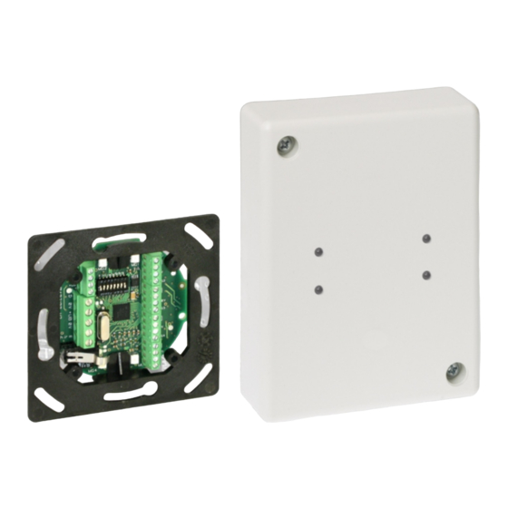
- Seite 1 Montage-Anschluss-Anleitung DUO I/O-Modul BUS-2/BUS-1, uP Art.-Nr. 010120.17 DUO I/O-Modul BUS-2/BUS-1, aP Art.-Nr. 010130 P02320-10-002-07 Anerkennung Änderungen G109010 vorbehalten 2014-04-25...
-
Seite 2: Inhaltsverzeichnis
Montage-Anschluss-Anleitung DUO I/O-Modul BUS-2/BUS-1 Inhaltsverzeichnis Seite 1. Anwendung ............. . . 3 2. -
Seite 3: Anwendung
Montage-Anschluss-Anleitung DUO I/O-Modul BUS-2/BUS-1 Anwendung Dieses Modul erweitert die Palette der Meldergruppen- und Steuermodule. Melder mit konventioneller Anschlusstechnik lassen sich damit in das BUS-System integrieren. Zusätzlich besitzt das Modul 2 Halbleiterausgänge für beliebige Schalt- und Steuerfunktionen. Das Modul kann alternativ am BUS-2 oder BUS-1 betrieben werden. Leistungsmerkmale Betrieb am BUS-2 oder alternativ am BUS-1 4 Meldergruppeneingänge mit Löschfunktion... -
Seite 4: Funktionsbeschreibung
Montage-Anschluss-Anleitung DUO I/O-Modul BUS-2/BUS-1 Funktionsbeschreibung Meldergruppeneingänge Die vier Meldergruppen arbeiten mit einer stabilisierten Spannung von 8 V DC, der Innenwiderstand beträgt 1k. Abschlusswiderstand: 12k1, Überwachungsbereich: ±20% (betriebsartabhängig veränderbar) Wahlweise kann bei jeder Meldergruppe der integrierte oder ein externer Abschlusswiderstand verwendet werden. Die Anschlussklemmen sind für Z-Verdrahtung geeignet. -
Seite 5: Betrieb Am Bus-1
Montage-Anschluss-Anleitung DUO I/O-Modul BUS-2/BUS-1 Betrieb am BUS-1 Datenübertragung Meldergruppen: Der Zustand jeder Meldergruppe wird separat Adresse Meldergruppe Anzeige Ausgang über eine eigene Adresse an die Zentrale über- LED1 tragen. Sabotageüberwachung: LED2 Eine Deckelkontakt-Auslösung wird auf allen 4 LED3 Adressen als Sabotage gemeldet. LED4 LED-Anzeige und Ausgänge: siehe nebenstehende Tabelle... -
Seite 6: Betrieb Am Bus-2
Montage-Anschluss-Anleitung DUO I/O-Modul BUS-2/BUS-1 Betrieb am BUS-2 Datenübertragung Die Zustände der 4 Meldergruppen werden getrennt im Busprotokoll über eine Adresse übertragen. Über diese Adresse erfolgt ebenfalls die Ansteuerung der LEDs. Eine Deckelkontakt-Auslösung wird im Busprotokoll separat als Sabotage an die Zentrale gemeldet. Betriebsarten Die Auswahl des Modultyps erfolgt über den DIP-Schalter S1/7 im Modul (siehe Kap. -
Seite 7: Programmierung
Montage-Anschluss-Anleitung DUO I/O-Modul BUS-2/BUS-1 Programmierung Die DIP-Schalter werden nur bei der Initialisierung (Anlegen der Betriebsspannung) ab- gefragt. Die Einstellung dieser Schalter ist deshalb nur im spannungslosen Zustand wirksam! BUS-2 BUS-1 DUO I/O-Modul 5 Eingangs-Modul Adresse Wertigkeit BUS-2 BUS-1 Auswahl BUS-System Betrieb am BUS-2: S1/8 ON Betrieb am BUS-1:... -
Seite 8: Montage Up Modul
Montage-Anschluss-Anleitung DUO I/O-Modul BUS-2/BUS-1 Montage uP-Modul Das uP-Modul ist für den Einbau in handelsübliche uP- und Hohlwanddosen Æ 60 mm vorgesehen. - Zugentlastung anbringen: Bringen Sie mit einem Kabelbinder eine Zugentlastung am Bügel auf der Rückseite des Moduls an. - Modul einbauen: Dosen aus Deutschland (DIN) und Österreich Platinen- halter... -
Seite 9: Anschlussplan
Montage-Anschluss-Anleitung DUO I/O-Modul BUS-2/BUS-1 Anschlussplan Übersicht Ausgang 1 LED2 LED1 Meldergruppe 1 Ausgang 2 +U_b Daten Meldergruppe 2 DIP-Schalter BUS-2/ +U_b BUS-1 Meldergruppe 3 Schirm Meldergruppe 4 LED4 LED3 Meldergruppeneingänge Die Anschlussbelegung der 4 Meldergruppen ist identisch. Beispiele: Anschluss Magnetkontakt GBS + MK (MK) oder Glasbruchsensor (GBS) in Z-Verdrahtung. -
Seite 10: Endmontage
Montage-Anschluss-Anleitung DUO I/O-Modul BUS-2/BUS-1 Endmontage 10.1 Montage uP Bei VdS gemäßer Anwendung muss der beigefügte Abdeckrahmen verwendet werden! Nur bei nicht VdS gemäßer Anwendung können Sie anstatt des beigefügten Abdeckrahmens eine Standard-Abdeckung für uP-Dosen verwenden (s. u.). Abdeckrahmen montieren Der Abdeckrahmen besitzt 4 Lichtleiter für die von außen sichtbare LED-Anzeige. Bei LEDs, die nicht sichtbar sein sollen, drücken Sie die Lichtleiter von innen nach außen aus dem Abdeck- rahmen heraus. -
Seite 11: Technische Daten
Der Überwachungsbereich kann je nach Zentralenausbau und Betriebsart des Moduls auf andere Werte programmiert werden (siehe Kap. 5.2.2). EN Konformität Art.-Nr. 010120.17 konform zu EN 50131-3, Grad 2, Klasse II Art.-Nr. 010130 konform zu EN 50131-3, Grad 2, Klasse II Zubehör für uP-Modul... - Seite 12 Honeywell Security Group Novar GmbH Johannes-Mauthe-Straße 14 P02320-10-002-07 D-72458 Albstadt 2014-04-25 www.honeywell.com/security/de © 2014 Novar GmbH...
- Seite 13 Mounting and Connection Instructions DUO I/O-Module BUS-2/BUS-1, f.m. Item no. 010120.17 DUO I/O-Module BUS-2/BUS-1, s.m. Item no. 010130 P02320-10-002-07 Subject to change approval G109010 without notice 2014-04-25...
-
Seite 14: Security Notes
Mounting and Connection Instructions DUO I/O-Module BUS-2/BUS-1 Table of contents Page 1. Application ............. . . 15 2. -
Seite 15: Application
Mounting and Connection Instructions DUO I/O Module BUS-2/BUS-1 Application This module is a further addition to the range of detector group and control modules. Detectors equipped with conventional connection technology can thus be integrated in the BUS system. The module also has 2 semiconductor outputs for switching and control functions. The module can be operated at either BUS-2 or BUS-1. -
Seite 16: Function
Mounting and Connection Instructions DUO I/O module BUS-2/BUS-1 Function Detector group inputs The four detector groups operate with a stabilized voltage of 8 V DC, the internal resistance is 1k. End of line resistor 12k1, monitoring range: ±20% (depending on the operating mode the values can be changed). -
Seite 17: Operation At Bus-1
Mounting and Connection Instructions DUO I/O-Module BUS-2/BUS-1 Operation at BUS-1 Data transmission Detector groups: Each detector group status is transmitted Address Detector group Indication Output separately via its own address to the control LED1 panel. Tamper monitoring: LED2 The triggering of the cover contact is signalled LED3 at all 4 addresses as tamper. -
Seite 18: Data Transmission
Mounting and Connection Instructions DUO I/O-Module BUS-2/BUS-1 Operation at BUS-2 Data transmission The states of the 4 detector groups are transmitted separately in the bus protocol via one address. The LEDs are also activated via this address. Triggering of a cover contact is signalled separately as tamper to the control panel in the bus protocol. -
Seite 19: Programming
Mounting and Connection Instructions DUO I/O-Module BUS-2/BUS-1 Programming The DIP switches are only queried during initialization (when the operating voltage is applied). Therefore, the setting of this switch is only effective when energized! BUS-2 BUS-1 DUO I/O-Module 5 Input module Address Valence BUS-2... -
Seite 20: Mounting F.m. Module
Mounting and Connection Instructions DUO I/O-Module BUS-2/BUS-1 Mounting f.m. module The module is intended for installation in commercially available flush mounted and cavity wall boxes with Æ 60 mm. - Attach pull relief: Attach a pull relief using a cable binder at the clip on the rear of the module. - Mount module: German boxes (DIN), Austrian boxes PCB mount... -
Seite 21: Connection Diagram
Mounting and Connection Instructions DUO I/O-Module BUS-2/BUS-1 Connection diagram Overview Output 1 LED2 LED1 Detector group 1 Output 2 +U_b Data Detector group 2 DIP switch BUS-2/ BUS-1 +U_b Detector group 3 Shield Detector group 4 LED4 LED3 Detector group inputs The terminal allocation of the 4 detector groups is identical Example: Magnetic contact connection... -
Seite 22: Final Assembly
Mounting and Connection Instructions DUO I/O-Module BUS-2/BUS-1 Final assembly 10.1 Mounting f.m. For use in compliance with VdS, use the enclosed cover frame! For use not in compliance with VdS, use a standard cover for flush mounted boxes instead of the enclosed cover frame (s.b.). -
Seite 23: Technical Data
Depending on the control panel and the operating mode of the module, the monitoring range is programmable (see 5.2.2) EN Conformity Item no. 010120.17 as per EN 50131-3, Security grade 2, Environmental Class II Item no. 010130 as per EN 50131-3, Security grade 2, Environmental Class II Accessories for f.m. - Seite 24 Honeywell Security Group Novar GmbH Johannes-Mauthe-Straße 14 P02320-10-002-07 D-72458 Albstadt 2014-04-25 www.honeywell.com/security/de © 2014 Novar GmbH...