Herunterladen Inhalt Inhalt Diese Seite drucken
Parkside PTMI 180 A1 Bedienungs- Und Sicherheitshinweise Originalbetriebsanleitung

Parkside PTMI 180 A1 Bedienungs- Und Sicherheitshinweise Originalbetriebsanleitung

Inverter-schweißgerät
Inhaltsverzeichnis

Werbung

Verfügbare Sprachen

Verfügbare Sprachen

INVERTER WELDER PTMI 180 A1
GB
IE
CY
INVERTER WELDER
Operation and Safety Notes
Translation of the original instructions
DE
AT
CH
INVERTER-SCHWEIßGERÄT
Bedienungs- und Sicherheitshinweise
Originalbetriebsanleitung
IAN 389213_2107
GR
CY
ΣΥΣΚΕΥΗ ΗΛΕΚΤΡΟΣΥΓΚΟΛΛΗΣΗΣ
INVERTER
Υποδείξεις χειρισμού και ασφαλείας
Μετάφραση των αυθεντικών οδηγιών λειτουργίας
GB
IE
CY

Werbung

Inhaltsverzeichnis
loading

Inhaltszusammenfassung für Parkside PTMI 180 A1

  • Seite 1 INVERTER WELDER PTMI 180 A1 ΣΥΣΚΕΥΗ ΗΛΕΚΤΡΟΣΥΓΚΟΛΛΗΣΗΣ INVERTER WELDER INVERTER Operation and Safety Notes Translation of the original instructions Υποδείξεις χειρισμού και ασφαλείας Μετάφραση των αυθεντικών οδηγιών λειτουργίας INVERTER-SCHWEIßGERÄT Bedienungs- und Sicherheitshinweise Originalbetriebsanleitung IAN 389213_2107...
  • Seite 2 Before reading, unfold the page containing the illustrations and familiarise yourself with all functions of the device. Πριν ξεκινήσετε την ανάγνωση, ανοίξτε τη σελίδα με τις εικόνες και εξοικειωθείτε με όλες τις λειτουργίες της συσκευής. Klappen Sie vor dem Lesen die beiden Seiten mit den Abbildungen aus und machen Sie sich anschließend mit allen Funktionen des Gerätes vertraut.
  • Seite 3 –...
  • Seite 5: Inhaltsverzeichnis

    Table of pictograms used ..................Page Introduction ......................Page Intended use ......................Page Scope of delivery.......................Page Parts description ......................Page Technical Specifications ....................Page Safety instructions ....................Page Before using the device ...................Page Using the device .......................Page MMA welding ......................Page Welding ........................Page TIG welding ......................Page Maintenance and cleaning ..................Page Information about recycling and disposal .............Page EC Declaration of Conformity ..................Page Warranty and service information .................Page...
  • Seite 6: Introduction

    Tungsten inert gas welding mode t ON (max) Inverter Welder PTMI 180 A1 z Introduction Congratulations! You have purchased one of our high-quality products. Please familiarise yourself with the product before using it for the first time. Please also read the safety instructions carefully.
  • Seite 7: Parts Description

    z Parts description Carrying strap TIG torch 2 MMA welding electrodes (2 x 2.5 mm) Control button 1 TIG electrode 1.6 mm Control wheel Mains cable Earthing clamp ON/OFF switch Electrode holder z Technical Specifications Mains connection: 230 V ~ 50 Hz (alternating current) Max.
  • Seite 8 cable. Disconnect the plug from the socket prior to setting up the device in another location. If the device is not in operation, always switch it off by pressing „ the ON/OFF switch. Place the electrode holder on an insulated surface and only remove the electrodes from the holder after allowing it to cool down for 15 minutes.
  • Seite 9: Potential Hazards During Electric Arc Welding

    ATTENTION! During the operation of the welder, other consumers may experience „ problems with the voltage supply depending on the network condi- tions at the connection point. In case of doubt, please contact your energy supply company. During the operation of the welder, other devices may malfunction, „...
  • Seite 10: Risk Of Electric Shock

    No welding work may be carried out on containers that have „ been used for storing gases, fuels, mineral oils or similar – even if they have been empty for a long time – as possible residues may present a risk of explosion. Special regulations apply in rooms where there is a risk of fire or „...
  • Seite 11 DANGER FROM ARC BEAMS: Arc beams can damage your eyes and injure your skin. Wear a „ hat and safety goggles. Wear hearing protection and high, closed shirt collars. Wear welding safety helmets and make sure you use the appropriate filter settings. Wear complete body protection. DANGER FROM ELECTROMAGNETIC FIELDS: Welding current generates electromagnetic fields.
  • Seite 12: Welding In Tight Spaces

    In wet, humid or hot workplaces where the air humidity or sweat „ significantly reduces the resistance of human skin and the insulating properties or effect of protective equipment. Even a metal conductor or scaffolding can create an environment „ with increased electrical hazard.
  • Seite 13: Protective Clothing

    The individual welding power sources, with their individual control units and connections, must be clearly marked, in order to be able to identify which device belongs to which welding power circuit. z Using shoulder straps Welding must not take place if the welding power source is being carried e.g.
  • Seite 14: Emc Device Classification

    z EMC Device Classification According to the standard IEC 60974-10, this is a welder in elec- tromagnetic compatibility Class A. Class A devices are devices that are suitable for use in all other areas except living areas and areas that are directly connected to a low-voltage supply mains that (also) supplies residential buildings.
  • Seite 15: Before Using The Device

    the device is only connected to a supply with an Ssc short circuit power which is larger or equal to 6106.5 W. Note! The device is only designed for use with a power supply where the permissible mains Zmax impedance is equal to or below 0.225 Ω. If you are in any doubt, then please contact an electrical professional.
  • Seite 16: Welding

    ATTENTION: Make sure that you do not rub the electrodes onto the workpiece. Doing this can damage the workpiece and make it more difficult to ignite the arc. After the arc is ignited, maintain the correct gap from the workpiece. The distance should be appropriate to the diameter of the electrode used.
  • Seite 17: Tig Welding

    z TIG welding Make sure that the ON/OFF switch is set to position “O” (“OFF”) or that the mains cable is not plugged into the socket. „ To do this, connect the connector of the earth terminal with the relevant output on the inverter welder (marked with “+”).
  • Seite 18: Ec Declaration Of Conformity

    C. M. C. GmbH Responsible for documentation: Dr. Christian Weyler Katharina-Loth-Str. 15 66386 St. Ingbert GERMANY hereby take sole responsibility for declaring that the product Inverter Welder PTMI 180 A1 IAN: 389213_2107 Art. no.: 2424 Year of manufacture: 2022/18 Model:...
  • Seite 19: Warranty And Service Information

    z Warranty and service information Warranty from Creative Marketing & Consulting GmbH Dear Customer, The warranty for this equipment is 3 years from the date of purchase. In the event of product defects, you have legal rights against the retailer of this product. Your statutory rights are not affected in any way by our warranty conditions, which are described below.
  • Seite 20: Service

    In the event of malfunctions or other defects, please first contact our service department below by phone or email. If your product is found to be defective, you can then send your product with proof of purchase (till receipt) and a statement describing what the fault involves and when it occurred free of charge to the service address given.
  • Seite 21 Πίνακας των εικονοσυμβόλων που χρησιμοποιούνται ..........Σελίδα Εισαγωγή ..........................Σελίδα Ενδεδειγμένη χρήση ......................Σελίδα Έκταση παράδοσης ......................Σελίδα Περιγραφή εξαρτημάτων ....................Σελίδα Τεχνικά χαρακτηριστικά ..................... Σελίδα Υποδείξεις ασφαλείας ....................... Σελίδα Πριν από τη θέση σε λειτουργία ..................Σελίδα Θέση σε λειτουργία ......................Σελίδα Συγκόλληση...
  • Seite 22: Εισαγωγή

    συγκόλλησης σε συνεχή αδρανούς αερίου λειτουργία t ON (max) Συσκευή ηλεκτροσυγκόλλησης inverter PTMI 180 A1 z Εισαγωγή Συγχαρητήρια! Αποφασίσατε να αποκτήσετε ένα προϊόν κορυφαίας ποιότητας. Εξοικειωθείτε με το προϊόν πριν το θέσετε σε λειτουργία για πρώτη φορά. Μελετήστε επομένως προσεκτικά τις υποδείξεις ασφαλείας. Η θέση αυτού του προϊόντος σε...
  • Seite 23: Έκταση Παράδοσης

    z Έκταση παράδοσης 1 συσκευή ηλεκτροσυγκόλλησης inverter 1 ζώνη μεταφοράς 1 τσιμπίδα ηλεκτροδίων (MMA) 2 ηλεκτρόδια συγκόλλησης MMA (2 x 2,5 mm) 1 καυστήρας WIG 1 ηλεκτρόδιο WIG 1,6 mm 1 σώμα 1 εγχειρίδιο με οδηγίες χρήσης z Περιγραφή εξαρτημάτων Ζώνη...
  • Seite 24 Διατηρείτε τα υλικά συσκευασίας μακριά από ΠΡΟΕΙ∆ΟΠΟΙΗΣΗ! „ μικρά παιδιά. Υπάρχει κίνδυνος ασφυξίας! Αναθέτετε επισκευές ή/και εργασίες συντήρησης μόνο σε εκπαι- „ δευμένους ηλεκτρολόγους. Χρησιμοποιείτε αποκλειστικά τα καλώδια συγκόλλησης που „ παρέχονται μαζί με τη συσκευή. Κατά τη λειτουργία της, η συσκευή δεν πρέπει να ακουμπά απευ- „...
  • Seite 25 παράδοση. Χρησιμοποιήστε γάντια και στεγνή προστατευτική ενδυμασία, χωρίς λάδι και γράσο, για να προστατεύετε το δέρμα σας από την υπεριώδη ακτινοβολία του ηλεκτρικού τόξου. Μην χρησιμοποιείτε την πηγή ρεύματος ΠΡΟΕΙ∆ΟΠΟΙΗΣΗ! „ συγκόλλησης για το ξεπάγωμα σωλήνων. Προσέξτε: Η ακτινοβολία του ηλεκτρικού τόξου μπορεί να προκαλέσει βλάβες „...
  • Seite 26 Εάν παρουσιαστούν ηλεκτρικές τάσεις επαφής, απενεργοποιήστε „ αμέσως τη συσκευή και αναθέστε τον έλεγχό της σε ηλεκτρολόγο. Στην πλευρά του ρεύματος συγκόλλησης, φροντίζετε πάντα για „ καλές ηλεκτρικές επαφές. Κατά τη συγκόλληση, φοράτε πάντα και στα δύο χέρια μονωτικά „ γάντια.
  • Seite 27 αδειούχος συγκολλητές. Τέτοια παραδείγματα είναι τα δοχεία υπό πίεση, οι ράγες, οι κοτσαδόροι κτλ. ΠΡΟΣΟΧΗ! Συνδέετε το σώμα πάντα όσο το δυνατό πιο „ κοντά στο σημείο συγκόλλησης, έτσι ώστε το ρεύμα συγκόλλησης να μπορεί να ακολουθήσει τη συντομότερη δυνατή διαδρομή από...
  • Seite 28 ΚΙΝΔΥΝΟΣ ΑΠΟ ΑΚΤΙΝΕΣ ΗΛΕΚΤΡΙΚΟΥ ΤΟΞΟΥ: Οι ακτίνες ηλεκτρικού τόξου μπορεί να προκαλέσουν βλάβη „ στα μάτια και τραυματισμούς στο δέρμα. Φορέστε καπέλο και γυαλιά ασφαλείας. Φορέστε ωτασπίδες και ρούχο με ψηλό, κλειστό γιακά. Φοράτε μάσκα προστασίας ηλεκτροσυγκολλητή και προσέξτε τις σωστές ρυθμίσεις του φίλτρου. Φορέστε πλήρης προστασία...
  • Seite 29 Σε χώρους εργασίας, στους οποίους υπάρχει περιορισμός „ κίνησης, με αποτέλεσμα ο συγκολλητής να εργάζεται σε μια αναγκαστική στάση (π.χ. γονατιστός, καθιστός, ξαπλωτός) και να ακουμπάει ηλεκτρικά αγώγιμα εξαρτήματα. Σε χώρους εργασίας, οι οποίοι είναι ηλεκτρικά αγώγιμα περι- „ ορισμένοι εξ ολοκλήρου ή εν μέρει και στους οποίους υπάρχει μεγάλος...
  • Seite 30 Η συγκόλληση σε στενούς χώρους επιτρέπεται μόνο, όταν πολύ „ κοντά υπάρχουν ενημερωμένα πρόσωπα, τα οποία μπορούν να επέμβουν σε περίπτωση έκτακτης ανάγκης. Εδώ πρέπει να πραγματοποιείται μια αξιολόγηση από έναν ειδικό πριν από τη διαδικασία συγκόλλησης, για να προσδιοριστεί, ποια βήματα...
  • Seite 31 Και στα δύο χέρια πρέπει να φοράτε μακριά γάντια από κατάλληλο „ υλικό (δέρμα). Πρέπει να είναι σε άψογη κατάσταση. Για την προστασία των ρούχων από σπινθήρες και καψίματα „ πρέπει να φοράτε κατάλληλες ποδιές. Εάν απαιτείται από το είδος των εργασιών, π.χ. συγκόλληση πάνω από το κεφάλι, πρέπει...
  • Seite 32 εργασία με ηλεκτρικό τόξο, είναι υπεύθυνος ο χρήστης και ο χρήστης πρέπει να λαμβάνει κατάλληλα προστατευτικά μέτρα. Στην περίπτωση αυτή, ο χρήστης πρέπει να λαμβάνει ιδιαίτερα υπόψη τα εξής: καλώδια τροφοδοσίας, ελέγχου, σηματοδότησης και τηλεπικοι- – νωνιών υπολογιστές και άλλες συσκευές ελεγχόμενες με μικροεπεξερ- –...
  • Seite 33: Πριν Από Τη Θέση Σε Λειτουργία

    z Πριν από τη θέση σε λειτουργία Αφαιρέστε τη συσκευή και τα αξεσουάρ από τη συσκευασία και ελέγξτε τα για ζημιές (π.χ. ζημιές από τη μεταφορά). Συνδέστε την τσιμπίδα ηλεκτροδίων για συγκόλληση MMA ή τον καυστήρα WIG για συγκόλ- „ ληση...
  • Seite 34: Συγκόλληση

    Η γωνία ανάμεσα στο ηλεκτρόδιο και στην κατεύθυνση εργασίας θα πρέπει να βρίσκεται μεταξύ 20° και 30°. ΠΡΟΣΟΧΗ: Η τσιμπίδα συγκόλλησης και το ηλεκτρόδια συγκόλλησης πρέπει να τοποθετούνται μετά τη διαδικασία συγκόλλησης στη μονωμένη βάση. Μόνο όταν κρυώσει το ηλεκτρόδιο, μπορείτε να...
  • Seite 35: Συντήρηση Και Καθαρισμός

    Συνδέστε για αυτόν τον σκοπό τη σύνδεση του σώματος με την αντίστοιχη έξοδο στη συσκευή „ ηλεκτροσυγκόλλησης inverter (επισημαίνεται με «+»). Συνδέστε τη σύνδεση του καυστήρα WIG με την αντίστοιχη έξοδο στη συσκευή ηλεκτροσυγκόλλησης „ inverter (επισημαίνεται με «-»). Φορέστε σύμφωνα με τις οδηγίες κατάλληλη προστατευτική ενδυμασία και προετοιμάστε τον χώρο „...
  • Seite 36: Δήλωση Συμμόρφωσης Εε

    Η εταιρεία C. M. C. GmbH Υπεύθυνος τεκμηρίωσης: Dr. Christian Weyler Katharina-Loth-Str. 15 DE-66386 St. Ingbert ΓΕΡΜΑΝΙΑ δηλώνει ως μοναδική υπεύθυνη, ότι το προϊόν Συσκευή ηλεκτροσυγκόλλησης inverter PTMI 180 A1 IAN: 389213_2107 Αρ. είδους: 2424 Έτος κατασκευής: 2022/18 Μοντέλο: PTMI 180 A1 ικανοποιεί...
  • Seite 37: Υποδείξεις Για Τη Διεκπεραίωση Της Εγγύησης Και Του Σέρβις

    St. Ingbert, 23/12/2021 Dr. Christian Weyler - Διασφάλιση ποιότητας - z Υποδείξεις για τη διεκπεραίωση της εγγύησης και του σέρβις Εγγύηση της Creative Marketing & Consulting GmbH Αγαπητέ πελάτη, αυτή η συσκευή καλύπτεται από εγγύηση 3 ετών από την ημερομηνία αγοράς. Αν...
  • Seite 38: Διεκπεραίωση Σε Περίπτωση Εγγύησης

    z Διεκπεραίωση σε περίπτωση εγγύησης Για τη γρήγορη διεκπεραίωση του θέματός σας, ακολουθήστε τις εξής υποδείξεις: Έχετε στη διάθεσή σας σε όλες τις ερωτήσεις σας την απόδειξη της ταμειακής μηχανής και τον αριθμό προϊόντος (π.χ. IAN) ως αποδεικτικά της αγοράς. Ο αριθμός προϊόντος υπάρχει στην πινακίδα τύπου, σε εγχάραξη, στο εξώφυλλο...
  • Seite 39 Tabelle der verwendeten Piktogramme ..............Seite Einleitung ........................Seite Bestimmungsgemäße Verwendung ................Seite Lieferumfang ......................Seite Teilebeschreibung ......................Seite Technische Daten .......................Seite Sicherheitshinweise ....................Seite Vor Inbetriebnahme ....................Seite Inbetriebnahme ......................Seite MMA Schweißen .......................Seite Schweißen ........................Seite WIG Schweißen ......................Seite Wartung und Reinigung ..................Seite Umwelthinweise und Entsorgungsangaben ............Seite EU-Konformitätserklärung ..................Seite Hinweise zu Garantie und Serviceabwicklung .............Seite Garantiebedingungen ....................Seite...
  • Seite 40: Einleitung

    Bemessungswert im ßen fortlaufenden Modus t ON (max) Inverter-Schweißgerät PTMI 180 A1 z Einleitung Herzlichen Glückwunsch! Sie haben sich für ein hochwertiges Produkt entschieden. Machen Sie sich vor der ersten Inbetriebnahme mit dem Produkt vertraut. Lesen Sie hierzu aufmerksam die Sicherheitshinweise. Die Inbetriebnahme dieses Produktes darf nur durch unterwiesene Personen erfolgen.
  • Seite 41: Teilebeschreibung
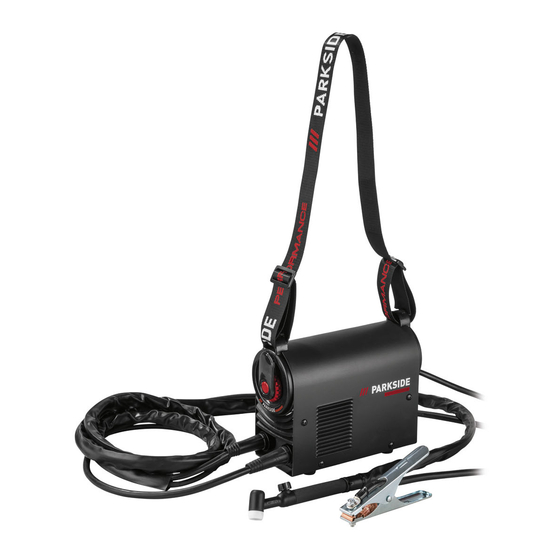
    z Teilebeschreibung Tragegurt WIG­Brenner 2 Schweißelektroden MMA (2 x 2,5 mm) Kontrolltaste 1 WIG Elektrode 1,6 mm Kontrollrad Netzkabel Masseklemme EIN­ / AUS­Schalter Elektrodenhalter z Technische Daten Netzanschluss: 230 V ~ 50 Hz (Wechselstrom) Max. Schweißstrom und die entsprechende 20 A/18,8 V ­ 180 A/25,2 V genormte Arbeitsspannung: Bemessungswert der Netzspannung: : 230 V...
  • Seite 42 klemmt werden, damit immer genügend Luft durch die Lüftungs­ schlitze aufgenommen werden kann. Vergewissern Sie sich, dass das Gerät richtig an die Netzspannung angeschlossen ist. Vermei­ den Sie jede Zugbeanspruchung der Netzleitung. Ziehen Sie den Netzstecker aus der Steckdose, bevor Sie das Gerät an einem an­ deren Ort aufstellen.
  • Seite 43: Gefahrenquellen Beim Lichtbogenschweißen

    schmolzenem Metall, das geschweißte Werkstück beginnt zu glü­ hen und bleibt relativ lange sehr heiß. Berühren Sie das Werkstück deshalb nicht mit bloßen Händen. Beim Lichtbogenschweißen werden gesundheitsschädliche Dämpfe „ freigesetzt. Achten Sie darauf, diese möglichst nicht einzuatmen. Schützen Sie sich gegen die gefährlichen Effekte des Lichtbogens „...
  • Seite 44 Geeignete Schutzkleidung tragen, keine synthetischen Kleidungs­ „ stücke. Nicht mit ungeschützten Augen in den Lichtbogen sehen, nur „ Schweißer­Schweißschirm mit vorschriftsmäßigem Schutzglas nach DIN verwenden. Der Lichtbogen gibt außer Licht­ und Wärmestrah­ len, die eine Blendung bzw. Verbrennung verursachen, auch UV­ Strahlen ab.
  • Seite 45: Gefährdung Durch Elektrischen Schlag

    Der Ausgang ist bei einer Umgebungstemperatur von 20 °C be­ „ messen. Die Schweißzeit kann bei höheren Temperaturen verrin­ gert sein. GEFÄHRDUNG DURCH ELEKTRISCHEN SCHLAG: Elektrischer Schlag von einer Schweißelektrode kann tödlich sein. „ Nicht bei Regen oder Schnee schweißen. Trockene Isolierhand­ schuhe tragen.
  • Seite 46: Umgebung Mit Erhöhter Elektrischer Gefährdung

    den. Tauschen Sie beschädigte oder zerkratzte Schutzscheiben sofort aus. Ersetzen Sie beschädigte oder stark verschmutzte bzw. verspritzte „ Komponenten unverzüglich. Das Gerät darf nur von Personen betrieben werden, die das 16. „ Lebensjahr vollendet haben. Machen Sie sich mit den Sicherheitsvorschriften für das Schweißen „...
  • Seite 47: Schweißen In Engen Räumen

    gesehen sein, der bei einem Ableitstrom von nicht mehr als 30 mA betrieben wird und alle netzbetriebenen Einrichtungen in der Nähe versorgt. Der Fehlerstrom­Schutzschalter muss für alle Stromarten ge­ eignet sein. Es müssen Mittel zum schnellen elektrischen Trennen der Schweiß­ stromquelle oder des Schweißstromkreises (z.B.
  • Seite 48: Schutzkleidung

    Das Risiko, das Gleichgewicht zu verlieren, wenn angeschlossene „ Leitungen oder Schläuche gezogen werden Die erhöhte Gefährdung eines elektrischen Schlages, da der „ Schweißer mit Erde in Berührung kommt, wenn er eine Schweiß­ stromquelle der Klasse I verwendet, deren Gehäuse durch ihren Schutzleiter geerdet ist.
  • Seite 49: Warnhinweis

    angeschlossen sind, das (auch) Wohngebäude versorgt. Geräte der Klasse A müssen die Grenzwerte der Klasse A einhalten. WARNHINWEIS: Geräte der Klasse A sind für den Betrieb in einer industriellen Umgebung vorgesehen. Wegen der auftretenden leis­ tungsgebundenen als auch gestrahlten Störgrößen kann es möglicher­ weise Schwierigkeiten geben, die elektromagnetische Verträglichkeit in anderen Umgebungen sicherzustellen.
  • Seite 50: Vor Inbetriebnahme

    Hinweis! Das Gerät ist nur für den Einsatz mit einer Stromversorgung geeignet, deren zulässige Netzimpedanz Zmax bei 0,225 Ω oder darunter liegt. Falls Sie Zweifel haben, konsultieren Sie einen Elektro­Fachmann. z Vor Inbetriebnahme Entnehmen Sie das Gerät und das Zubehör aus der Verpackung und überprüfen Sie diese auf Schäden (z. B.
  • Seite 51: Schweißen

    Tragen Sie geeignete Schutzausrüstung und beginnen Sie mit dem Schweißvorgang. „ Um den Arbeitsvorgang zu beenden, stellen Sie den EIN­ / AUS­Schalter auf Position „ „O“(„OFF“). ACHTUNG: Achten Sie darauf, die Elektrode nicht am Werkstück zu reiben. Damit kann das Werkstück beschädigt und die Zündung des Lichtbogens erschwert werden.
  • Seite 52: Wig Schweißen

    HINWEIS: Nach vollständiger Abnutzung der Elektrode muss diese ausgetauscht werden. z WIG Schweißen Stellen Sie sicher, dass der EIN­ / AUS­Schalter auf Position „O“ („OFF“) gestellt ist bzw. dass das Netzkabel nicht in die Steckdose eingesteckt ist. Verbinden Sie dazu den Anschluss der Masseklemme mit dem entsprechenden Ausgang am „...
  • Seite 53: Eu-Konformitätserklärung

    EU-Konformitätserklärung Wir, die C. M. C. GmbH Dokumentenverantwortlicher: Dr. Christian Weyler Katharina­Loth­Str. 15 DE­66386 St. Ingbert DEUTSCHLAND erklären in alleiniger Verantwortung, dass das Produkt Inverter-Schweißgerät PTMI 180 A1 389213_2107 IAN: 2424 Art. ­ Nr.: 2022/18 Herstellungsjahr: PTMI 180 A1 Modell: den wesentlichen Schutzanforderungen genügt, die in den Europäischen Richtlinien...
  • Seite 54: Hinweise Zu Garantie Und Serviceabwicklung

    St. Ingbert, 23.12.2021 Dr. Christian Weyler ­ Qualitätssicherung ­ z Hinweise zu Garantie und Serviceabwicklung Garantie der Creative Marketing & Consulting GmbH Sehr geehrte Kundin, sehr geehrter Kunde, Sie erhalten auf dieses Gerät 3 Jahre Garantie ab Kauf­ datum. Im Falle von Mängeln dieses Produkts stehen Ihnen gegen den Verkäufer des Produkts gesetzli­ che Rechte zu.
  • Seite 55: Abwicklung Im Garantiefall

    z Abwicklung im Garantiefall Um eine schnelle Bearbeitung Ihres Anliegens zu gewährleisten, folgen Sie bitte den folgenden Hinwei­ sen: Bitte halten Sie für alle Anfragen den Kassenbon und die Artikelnummer (z. B. IAN) als Nachweis für den Kauf bereit. Die Artikelnummer entnehmen Sie bitte dem Typenschild, einer Gravur, dem Titel­ blatt Ihrer Anleitung (unten links) oder dem Aufkleber auf der Rück­...
  • Seite 56: Service

    z Service So erreichen Sie uns: DE, AT, CH Name: C. M. C. GmbH Internet­Adresse: www.cmc­creative.de E­Mail: service.de@cmc­creative.de service.at@cmc­creative.de service.ch@cmc­creative.de Telefon: +49 (0) 6894/ 9989750 (Normaltarif aus dem dt. Festnetz) Fax: +49 (0) 6894/ 9989729 Sitz: Deutschland IAN 389213_2107 Bitte beachten Sie, dass die folgende Anschrift keine Serviceanschrift ist. Kontaktieren Sie zunächst die oben benannte Servicestelle.
  • Seite 57 C.M.C. GmbH Katharina-Loth-Str. 15 DE-66386 St. Ingbert GERMANY Last Information Update · Έκδοση των πληροφοριών · Stand der Informationen: 12/2021 Ident.-No.: PTMI180A1122021-GB-IE-CY IAN 389213_2107...

Inhaltsverzeichnis