Emerson Alco Controls EXD-HP1 Betriebsanleitung
Überhitzungsregler mit modbus kommunikation
Verfügbare Sprachen
Verfügbare Sprachen
Quicklinks
G e n e r a l i n f o r m a t i o n :
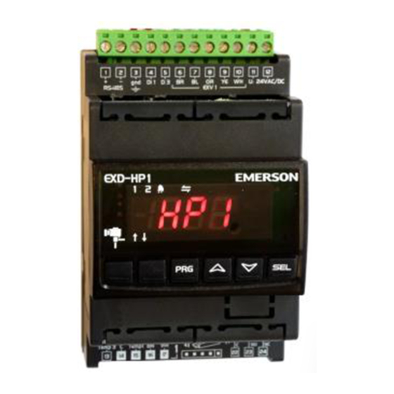
EXD-HP1/2 are stand-alone superheat and or economizer controllers. EXD-HP1 is intended
for operation of one EXM/EXL or EXN valve whereas EXD-HP2 is designed for operation
of two independent EXM/EXL or two EXN valves.
NOTE: It is possible to use only circuit 1 from EXD-HP2. In this case, the circuit 2
must be disabled (C2 parameter) and the sensors and the valve for the second circuit
are not needed.
ModBus communication is described in a Technical Information and it is not covered
by this document.
WARNING -Flammable refrigerants:
EXD-HP1/2 has a potential ignition source and does not comply with ATEX
requirements. Installation only in non-explosive environment. For flammable
refrigerants only use valves and accessories approved for it!
T e c h n i c a l D a t a :
Power supply
24 VAC/DC ±10 %; 1 A
EXD-HP1: 15 VA
Power consumption
EXD-HP2: 20 VA
Plug-in connector
Removable screw terminals wire size 0.14...1.5 mm
Protection class
IP20
Digital Inputs
Potential free contacts (free from voltage)
Temperature sensors
ECP-P30
Pressure sensors
PT5N (FLR) & PT5 (FLR)
Temperatures
Operating / Ambient -10...+60 °C
Output alarm relay
SPDT contact 24 VAC, 1 A inductive load;
24 VAC/DC 4 A resistive load
Activated/energized:
During normal operation (no alarm condition)
Deactivated/de-
During alarm condition or power supply is OFF
energized
Coil: EXM-125/EXL-125 or EXN-125
Stepper motor output
Valves: EXM/EXL-... or EXN-...
Type of action
1 B
Rated impulse voltage
0.5 kV
Pollution Degree
2
Mounting
For standard DIN rail
Marking
Dimensions
S a f e t y i n s t r u c t i o n s :
•
Read operating instructions thoroughly. Failure to comply can result in device
failure, system damage or personal injury.
•
This product is intended for use by qualified personnel having the appropriate
knowledge and skills like trained according to EN 13313 or a specific training for
flammable refrigerants.
•
Flammable refrigerants require special handling and care due to its flammability.
Sufficient ventilation is required during service of the system.
•
Ensure that the system is correctly labelled with applied refrigerant type and a warning
for explosion risk.
•
Contact with rapidly expanding gases can cause frostbite and eye damage. Proper
protective equipment (gloves, eye protection, etc.) has to be used.
•
Do not exceed the specified maximum ratings for temperature, voltage and current.
•
Before installation or service disconnect all voltages from system and device.
•
Do not operate system before all cable connections are completed.
•
Do not apply voltage to the controller before completion of wiring.
•
Entire electrical connections have to comply with local regulations.
•
Inputs are not isolated, potential free contacts needed to be used.
•
Disposal: Electrical and electronic waste must NOT be disposed of with other
commercial waste. Instead, it is the user responsibility to pass it to a designated
collection point for the safe recycling of Waste Electrical and Electronic Equipment
(WEEE directive 2019/19/EU). For further information, contact your local
environmental recycling center.
Emerson Climate Technologies GmbH
Pascalstrasse 65 I 52076 Aachen I Germany
O P E R A T I N G I N ST RU C T I O N S
EXD-HP1/2 Controller with
ModBus communication capability
2
www.climate.emerson.com/en-gb
E l e c t r i c a l c o n n e c t i o n a n d w i r i n g :
• Refer to the electrical wiring diagram for electrical connections.
• NOTE: Keep controller and sensor wiring well separated from supply power cables.
Minimum recommended distance 30mm.
• EXM-125, EXL-125 or EXN-125 coils are supplied with fix cable and JST terminal block
at cable end. Cut the wires close to terminal block. Remove the wire insulation
approximately 7 mm at the end. It is recommended that the wires end to be equipped
with core cable ends or metallic protective sleeve. When connecting the wires of
EXM/EXL or EXN, consider the colour coding as follows:
EXD
Terminal
EXD-HP1
6
BR
7
BL
8
OR
9
YE
10 WH
EXD-HP2
30 BR
31 BL
32 OR
33 YE
34 WH
•
The digital input DI1 (EXD-HP1) and DI1/D12 (EXD-HP1/2) are the interfaces
between
EXD-HP1/2
and
upper-level
communication has not been used. The external digital shall be operated in
function system's compressor/demand.
•
If the output relays are not utilized, the user must ensure appropriate safety
precautions are in place to protect the system.
Operating condition
Compressor starts/run
Compressor stops
NOTE: Connecting any EXD-HP1/2 inputs to the supply voltage will permanently
damage the EXD-HP1/2.
W i r i n g b a s e b o a r d ( E X D - H P 1 / 2 ) :
NOTE:
•
Base board is for function of superheat control or Economizer control.
•
Alarm relay, dry contact. Relay coil is not energized during alarm condition or power off.
•
Hot gas discharge sensor input is mandatory only for economizer control function.
WARNING: Use a class II category transformer for 24 VAC power supply. Do not
ground the 24 VAC lines. We recommend using individual transformers for EXD-
HP1/2 controller and for third party controllers to avoid possible interference or
grounding problems in the power supply.
OI_EXD-HP12_A1_A2L_A3_EN_DE_RU_Rev08_865921.docx
EXM/L-125 wire color
EXN-125 wire color
Brown
Blue
Orange
Orange
Yellow
Yellow
White
White
Brown
Blue
Orange
Orange
Yellow
Yellow
White
White
system
controller
if
Digital input status
closed (Start)
open (Stop)
PT5(N)
Date: 30.06.2022
EN
Red
Blue
Red
Blue
the
Modbus

Verwandte Anleitungen für Emerson Alco Controls EXD-HP1


Inhaltszusammenfassung für Emerson Alco Controls EXD-HP1
- Seite 5 Klasse II zu verwenden. Die 24 V Leitungen dürfen nicht geerdet werden. Wir • Digitaleingänge sind spannungsbehaftet; nur potentialfreie Schaltkontakte empfehlen die Verwendung jeweils separater EMERSON Transformatoren für EXD- verwenden. HP1/2 Regler und die Regler anderer Hersteller, weil unter Umständen über die •...
-
Seite 6: Modbus-Kommunikation
HINWEIS 2: Nach 30 Minuten, wechselt die Anzeige wieder auf den Index 0. Alarmanzeige zurückstellen / löschen (außer Hardwarefehler): • gleichzeitig mindestens 5 Sekunden drücken. Nach dem Löschen wird 2 Sekunden lang “CL” angezeigt. Emerson Climate Technologies GmbH www.climate.emerson.com/en-gb Date: 30.06.2022 Pascalstrasse 65 I 52076 Aachen I Germany OI_EXD-HP12_A1_A2L_A3_EN_DE_RU_Rev08_865921.docx... - Seite 7 1 = ein autom. Rückstellung 2 = ein - manuelle Rückstellung Grenzwert für Überhitzung Regelkreis 2 Frostschutzalarm Sollwert Regelkreis 1 Alarmverzug (Min) für Überhitzung Regelkreis 2 Alarmverzug Frostschutz (s) Emerson Climate Technologies GmbH www.climate.emerson.com/en-gb Date: 30.06.2022 Pascalstrasse 65 I 52076 Aachen I Germany OI_EXD-HP12_A1_A2L_A3_EN_DE_RU_Rev08_865921.docx...
- Seite 8 HINWEIS: Bei mehreren Störungen wird nur der Alarm mit der höchsten Priorität angezeigt. Erst nach dessen Beseitigung erscheint der nächste Alarm usw. bis alle Alarme beseitigt sind. Erst dann werden die Daten wieder angezeigt Emerson Climate Technologies GmbH www.climate.emerson.com/en-gb Date: 30.06.2022 Pascalstrasse 65 I 52076 Aachen I Germany OI_EXD-HP12_A1_A2L_A3_EN_DE_RU_Rev08_865921.docx...