Emerson EXD-HP1 Betriebsanleitung
Überhitzungsregler mit modbus kommunikation
Verfügbare Sprachen
Verfügbare Sprachen
Quicklinks
G e n e r a l i n f o r m a t i o n :
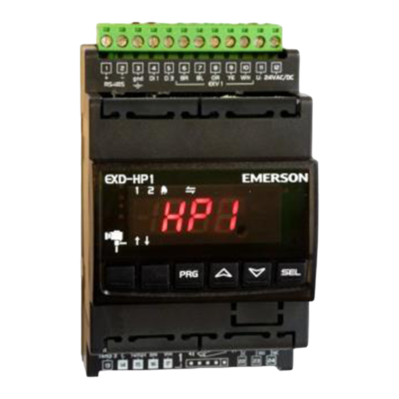
EXD-HP1/2 are stand-alone superheat and or economizer controllers. EXD-HP1 is
intended for operation of one EXM/EXL valve whereas EXD-HP2 is designed for
operation of two independent EXM/EXL valves.
Note: It is possible to use only circuit 1 from EXD-HP2. In this case, the circuit
2 must be disabled (C2 parameter) and the sensors and the valve for the second
circuit are not needed.
ModBus communication is described in a Technical Bulletin and it is not covered
by this document.
T e c h n i c a l D a t a :
Power supply
Power consumption
Plug-in connector
Protection class
Digital Inputs
Temperature sensors
Pressure sensors
Operating/surrounding temp.
Output alarm relay
Activated/energized: During normal operation (no alarm condition)
Deactivated/de-energized: During alarm condition or power supply is OFF
Stepper motor output
Mounting:
Marking
Dimensions (mm)
S a f e t y i n s t r u c t i o n s :
• Read operating instructions thoroughly. Failure to comply can result in device
failure, system damage or personal injury.
• It is intended for use by persons having the appropriate knowledge and skill.
• Before installation or service disconnect all voltages from system and device.
• Do not operate system before all cable connections are completed.
• Do not apply voltage to the controller before completion of wiring.
• Entire electrical connections have to comply with local regulations.
• Inputs are not isolated, potential free contacts needed to be used.
• Disposal: Electrical and electronic waste must NOT be disposed of with other
commercial waste. Instead, it is the user responsibility to pass it to a designated
collection point for the safe recycling of Waste Electrical and Electronic
Equipment (WEEE directive 2012/19/EU). For further information, contact
your local environmental recycling center.
E l e c t r i c a l c o n n e c t i o n a n d w i r i n g :
• Refer to the electrical wiring diagram for electrical connections.
• Note: Keep controller and sensor wiring well separated from supply power
cables. Minimum recommended distance 30 mm.
• EXM-125 / EXL-125 coils are supplied with fix cable and JST terminal block at
cable end. Cut the wires close to terminal block. Remove the wire insulation
approximately 7 mm at the end. It is recommended that the wires end to be
equipped with core cable ends or metallic protective sleeve. When connecting the
wires of EXM/EXL consider the color coding as follows:
EXD
Terminal
EXD-HP1
6
BR
7
BL
8
OR
9
YE
10
WH
EXD-HP2
30
BR
31
BL
32
OR
33
YE
34
WH
Emerson Climate Technologies GmbH
Am Borsigturm 31 I 13507 Berlin I Germany
EXD-HP1/2 Controller with ModBus
communication capability
24VAC/DC ±10%; 1A
EXD-HP1: 15VA
EXD-HP2: 20VA
Removable screw terminals wire size 0.14...1.5 mm
IP20
Potential free contacts (free from voltage)
ECP-P30
PT5
0...+55°C
SPDT contact 24V AC 1 A inductive load;
24V AC/DC 4 A resistive load
Coil: EXM-125/EXL-125
Valves: EXM/EXL-...
For standard DIN rail
,
EXM/L-125 wire color
Brown
Blue
Orange
Yellow
White
Brown
Blue
Orange
Yellow
White
www.emersonclimate.eu
Operating instruction
• The digital input DI1 (EXD-HP1) and DI1/D12 (EXD-HP1/2) are the
interfaces between EXD-HP1/2 and upper level system controller if the
Modbus communication has not been used. The external digital shall be
operated in function system's compressor/demand.
• If the output relays are not utilized, the user must ensure appropriate safety
precautions are in place to protect the system.
Operating condition
Compressor starts/run
Compressor stops
Note: Connecting any EXD-HP1/2 inputs to the supply voltage will
permanently damage the EXD-HP1/2.
W i r i n g b a s e b o a r d ( E X D - H P 1 / 2 ) :
2
Note:
• Base board is for function of superheat control or Economizer control.
• Alarm relay, dry contact. Relay coil is not energized during alarm condition or
power off.
• Hot gas discharge sensor input is mandatory only for economizer control function.
Warning: Use a class II category transformer for 24VAC power supply. Do
not ground the 24VAC lines. We recommend using individual transformers for
EXD-HP1/2 controller and for third party controllers to avoid possible
interference or grounding problems in the power supply.
Date: 08.09.2017
Digital input status
closed (Start)
open (Stop)
EXD-HP12_OI_ML_R03_865921.docx

Verwandte Anleitungen für Emerson EXD-HP1


Inhaltszusammenfassung für Emerson EXD-HP1
- Seite 5 EXM/L Adernfarbe EXD-HP1/2 sind autonome, universell einsetzbare Überhitzungs- und oder Braun EXD-HP2 Economiser-Regler. EXD-HP1 besitzt einen Regelkreis für ein Ventil der Baureihe Blau EXM/EXL, während EXD-HP2 Regelkreise für zwei Ventile EXM/EXL besitzt. Orange Hinweis: Es ist möglich nur den Kreislauf 1 vom EXD-HP2 zu verwenden. In Gelb diesem Falle muss der Kreislauf 2 über den Parameter C2 abgeschaltet werden;...
- Seite 6 Schutz des Verdichters und anderer Komponenten. Transformatoren für EXD-HP1/2 Regler und die Regler anderer Hersteller, • Wenn diese Hauptparameter eingestellt sind, ist der EXD-HP1/2 fertig zum Start. weil unter Umständen über die Erdleitungen Kurzschlüsse entstehen können. Alle anderen Parameter lassen sich bei Bedarf auch im laufenden Betrieb einstellen.
- Seite 7 Anzeigemode 0 = Standard Regelung; 1 = langsame Regelung; 2 = feste PID EXD-HP1= 0 (keine Anzeige: - - -); 1(Anzeige) Kältemittel EXD-HP2= 0 (keine Anzeige: - - -); 1 (Regelkr. 1); 2 (Regelkr. 2) 0 = R22; 1 = R134a; u0 2 = R410A;...
- Seite 8 Betriebsanleitung EXD-HP1/2 Überhitzungsregler mit ModBus Kommunikation F u n k t i o n d e s K o p i e r s c h l ü s s e l s Für Serienfertigung können Konfigurationsparameter mit dem Kopierschlüssel auf...