Werbung
Verfügbare Sprachen
Verfügbare Sprachen
Quicklinks
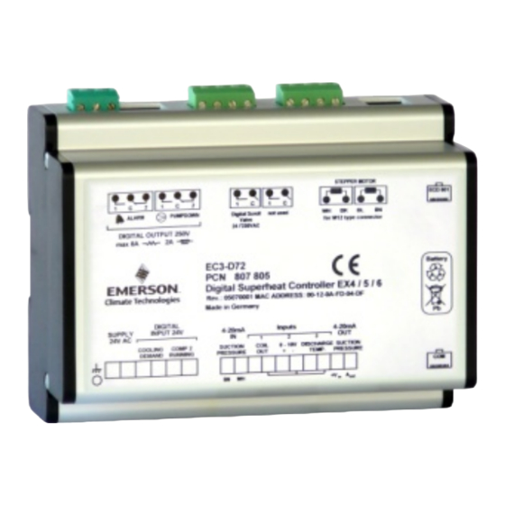
Description
EC3-D7x is the superheat controller with
TCP/IP connection for stepper motor driven
Alco Electrical Control Valves EX4...EX6 and
is optimized to operate with the Copeland
Digital Scroll series utilizing a 0-10V input
from a third party controller. The controller
synchronizes the PWM digital compressor
solenoid valve with the
superheat controlled by the electrical control valve; EX series. The EC3-D73 has the
same functionality but can only be set-up via the ECD-002 display. It has no external
communication functionality.
Note: This document contains short form instructions for experienced users.
!
Safety instructions:
•
Read installation instructions thoroughly. Failure to comply can result in device
failure, system damage or personal injury.
The product is intended for use by persons having the appropriate knowledge and
•
skills.
•
Disconnect all voltages from system before installation.
•
Do not operate the system before all cable connections are completed.
•
Comply with the local electrical regulations when wiring.
Note: The EC3-D7x series contains
acid battery.
The battery must NOT be disposed of with other commercial waste.
Instead, it is the user's responsibility to pass it to a designated collection point for the
safe recycling of batteries (harmonised directive 98/101/EEC). For further information
contact your local environmental recycling centre.
Technical data
Power supply
Power consumption
Plug-in connector
Grounding
Protection class
COM, TCP/IP connection
Connection to optional local
ECD-002
Digital Input; Cooling
demand
Digital Input; Comp2
running
NTC input; Coil-out
temperature sensor
NTC input; Discharge
temperature sensor
4-20 mA Analog input
4-20 mA Analog output
Deviation from input signal
Output alarm relay
(If L2 = 1)
Activated:
Deactivated:
Output pump down relay
(If L2 = 1)
Activated: During normal operation
Deactivated: All other conditions
If the output relays are not utilized, the user must ensure appropriate safety
!
precautions are in place to protect the system against damage caused by a power
failure.
Output Digital Scroll
Triac
Stepper motor output for
EX4...EX6
Ambient temperature range 0 ... 60°C
In order to provide system protection in the event of power loss, it is recommended
!
to change the battery annually.
Mounting
The EC3-D7x is designed to be mounted onto a standard DIN rail.
Electrical installation
Refer to the electrical wiring diagram for electrical connections.
•
•
Do not apply voltage to the controller before completion of wiring.
•
Ground the metal housing with a 6.3mm spade connector.
Emerson Climate Technologies GmbH
Am Borsigturm 31 I 13507 Berlin I Germany
Downloaded from
www.Manualslib.com
EC3-D7x Digital Superheat Controller
EC3-D72 with TCP/IP communication capability
a VRLA battery= valve regulated rechargeable lead-
24VAC ±10%; 50/60Hz; 1A
25VA max. including EX4 ... EX6
Removable screw terminals wire size 0,14 .. .1,5 mm
6,3 mm spade earth connector
IP20
RJ45 Ethernet
ECC-Nxx or CAT5 cable with RJ45 connectors
0/24VAC/DC for stop/start function. EX valve closes
during stop command. Typically thermostat or third party
controller.
0/24VAC/DC typically connected to auxiliary connection.
EX valve control loop remains active when input is 24V
and the Digital Scroll is idle.
Emerson temperature sensor ECN-N60 or ECN-P60
Copeland® NTC 86 kOhm at 25 °C
Emerson PT5-07M / PT5-18M / PT5-30M
rd
For connection to any 3
party controller with 12/24VDC
power supply and appropriate burden
±8% max
SPDT contact 24V AC/DC, 2 Amp inductive load
During normal operation (no alarm condition)
During alarm condition or power supply is OFF
SPDT contact 24V AC/DC, 2 Amp inductive load
24V or 230V AC output to activate PWM valve on Digital
Scroll
Maximum current 0.6A with nominal 24VDC operating
voltage
1 ... 25°C (for best battery life time)
> 35°C battery life time < 2 years
www.emersonclimate.eu
manuals search engine
Operating instruction
•
Important: Keep the controller and sensor wirings well separated from the mains
wiring. Minimum recommended distance 30mm.
Warning: Use a class II category transformer for the 24VAC power supply. Do not
ground the 24VAC lines. We recommend using individual transformers for the EC3
controller and for 3
problems in the power supply. Connecting any EC3 inputs to the mains voltage will
permanently damage the EC3.
Digital input status is dependant on operation of compressor/0-10V input
System
Operating
condition
Comp. 1 &
Comp.2 in stop
mode
Comp. 1 in run &
Comp.2 in stop
mode)
Comp 1 & Comp.
2 in run mode
Comp.1 in stop
and Comp. 2 in
run mode starts
Digital comp. should always be regarded as base load; compressor 1
Wiring
2
A: White wire
C: Blue wire
E: M12 Plug cable assembly EX5-Nxx for
connection to EX4/EX5/EX6
F: 24V/230V Triac output to the PWM
Digital Scroll valve
G: Remote control panel, system
controller
H: Alarm relay, dry contact. Relay coil is
not energised at Alarm or power off
!
The use of the relay is essential to protect
the system in case of a power failure; if the
communications interface or the ECD-002
is not utilized.
I: Digital input 1: "Cooling demand"
(Digital compressor run: (0V/open =
Stop; 24V/closed = Control Start;)
Date: 13.06.2016
rd
party controllers to avoid possible interference or grounding
Digital Inputs
0-10V input from third party controller
"Cooling demand"
ECV remains closed irrespective of voltage
open (0V)
input value
"Comp 2 Running"
open (0V)
ECV active
"Cooling demand"
Input =0V: digital valve capacity at 10%
closed (24V) /
default capacity.
"Comp 2 Running"
When the digital comp. is in by-pass the
open (0V)
ECV will:
Close when capacity is <70%
Be inhibited when the capacity is >70%
"Cooling demand"
ECV active
closed (24V) /
The ECV will always modulate even when
"Comp 2 Running"
the digital compressor is in by-pass mode.
closed (24V)
"Cooling demand"
ECV remains closed irrespective of voltage
open (0V) /
input value
"Comp 2 Running"
closed (24V)
B: Black wire
J:
Transformer Class II, 24VAC
D: Brown wire
secondary / 25VA min. Model ECT-
323
K: Third party controller (can use the
suction pressure (4-20mA) analogue
output signal from the EC3)
L: Pump down relay, dry contact. Relay
is energized during normal operation.
M: Digital input 2: "Comp. 2 running"
(0V/open = Comp. 2 stop; 24V/closed
= Comp. 2 running
N: Discharge Temp. Sensor
Copeland® NTC
O: 0-10V Digital Scroll capacity
demand signal from the system
controller
P: ECN-N60 Coil out sensor
EC3-D72_OI_EN_R05_865019.docx
Werbung

Verwandte Anleitungen für Emerson EC3-D7 Serie


Inhaltszusammenfassung für Emerson EC3-D7 Serie
- Seite 5 Emerson Temperatursensor ECN-N60 oder ECN-P60 Verdampferaustrittsfühler NTC Analogeingang für Copeland® NTC 86 kOhm bei 25 °C Sensor Austrittstemperatur 4-20 mA Analogeingang von Emerson PT5-07M / PT5-18M / PT5-30M 4-20 mA Analogausgang für externen Regler mit 12/24VDC Speisespannung und geeignetem internen Widerstand Abweichung vom Eingangssignal ±...
- Seite 6 (PRG & SEL) 5s drücken gelangt man, indem man mit dem Mauszeiger über die entsprechende Schaltfläche oben an der Monitorseite fährt und dann die linke Maustaste drückt. Emerson Climate Technologies GmbH www.emersonclimate.eu Am Borsigturm 31 I 13507 Berlin I Germany Date: 13.06.2016...
- Seite 7 • Beide Seiten gleichmäßig und nicht zu fest anziehen. Achtung: durch zu festes Anziehen können die Halterungen abbrechen. Emerson Climate Technologies GmbH www.emersonclimate.eu Am Borsigturm 31 I 13507 Berlin I Germany Date: 13.06.2016 EC3-D72_OI_DE_R05_865019.doc Downloaded from www.Manualslib.com manuals search engine...
- Seite 8 Digitaleingang einmal je Woche für 5 Sekunden permanenter Überbrückung des 24V Digitaleingangs unterbrechen. Abmessungen EC3-D72/D73 ECD-002 Revision applicable to EC3-D72 software release =>114, rev 6 Emerson Climate Technologies GmbH www.emersonclimate.eu Am Borsigturm 31 I 13507 Berlin I Germany Date: 13.06.2016 EC3-D72_OI_DE_R05_865019.doc Downloaded from www.Manualslib.com...