Logotherm LogoCool S-Line Technische Information Für Montage Und Betrieb
Inhaltsverzeichnis
Verfügbare Sprachen
Verfügbare Sprachen
Technische Information für Montage und Betrieb
Leistungsstufen
(Power levels)
Meibes System-Technik GmbH
Ringstraße 18 · D 04827 Gerichtshain · Tel.: +49 (0) 3 42 92 7 13-0 · Fax 7 13-50
Internet: www.meibes.de · E-Mail: info@meibes.com
LogoCool
S-Line
1 bis (to) 5 kW
2 bis (to) 12 kW
5 bis (to) 16 kW
S-Line
Technische Information für Montage und Betrieb,
Technical Information for Installation and Operation,
Version
M-Line
9 bis (to) 24 kW
M-Line
DE
Seite 2
GB
Page 43
Kapitel
Inhaltsverzeichnis

Verwandte Anleitungen für Logotherm LogoCool S-Line


Inhaltszusammenfassung für Logotherm LogoCool S-Line
- Seite 1 Technische Information für Montage und Betrieb LogoCool Version S-Line M-Line Leistungsstufen 1 bis (to) 5 kW 9 bis (to) 24 kW (Power levels) 2 bis (to) 12 kW 5 bis (to) 16 kW M-Line S-Line Technische Information für Montage und Betrieb, Seite 2 Technical Information for Installation and Operation, Page 43...
-
Seite 2: Inhaltsverzeichnis
Inhaltsverzeichnis Sicherheitshinweise _________________________________________ 3 Funktionsbeschreibung ______________________________________ 4 LogoCool- dezentrale Wohnungsstation _________________________ 5 Technische Daten ______________________________________________________________________ 5 Aufbau und Komponenten ________________________________________________________________ 8 Montage ____________________________________________________________________________ 10 Fronthaube und Gehäuse _________________________________________________________________ 12 Elektrischer Anschluss ___________________________________________________________________ 13 Einzelne Komponenten der Stationen _________________________ 14 Umwälzpumpe ________________________________________________________________________ 14 Druckunabhängiges Regulierventil __________________________________________________________ 16 Schmutzfänger ________________________________________________________________________ 18 Sicherheitsventil und Manometer ___________________________________________________________ 19... -
Seite 3: Sicherheitshinweise
Bitte befolgen Sie diese Sicherheitshinweise genau, um Gefahren und Schäden für Menschen und Sachwerte auszuschließen. 1. Sicherheitshinweise Zielgruppe Diese Anleitung richtet sich ausschließlich an autorisierte Fachkräfte. -Arbeiten an der Heizungsanlage, dem Trinkwasser- sowie Gas- und Stromnetz dürfen nur von Fachkräften bzw. Installateuren, die durch das jeweilig zuständige Versorgungsunternehmen dazu berechtigt sind, durchgeführt werden. -
Seite 4: Funktionsbeschreibung
2. Funktionsbeschreibung LogoCool-Stationen sind eine neue Generation von Wohnungsübergabestationen für die Übertragung von Kühlenergie in Wohnungen, Appartements sowie kommerziellen Gebäuden. LogoCool entspricht den Anforderungen hinsichtlich einer effizienten und einfachen Anwendung, bedingt durch die stufenlose primäre Volumenstrom- und damit Primärenergieeinstellung des Ballorex Dynamic (druckunabhängiges Regulierventil). -
Seite 5: Logocool- Dezentrale Wohnungsstation
3. LogoCool- dezentrale Wohnungsstation 3.1 Technische Daten Kühlübergabestation S-Line: Für wasserbasierende Kühlsysteme Kühlleistungen 1 kW bis 5 kW Art.-Nr. 10610.32 2 kW bis 12 kW Art.-Nr. 10610.22 5 kW bis 16 kW Art.-Nr. 10610.12 Abmessung Gehäuse (HxBxT) in mm 675 x 630 x 263 Kühlübergabestation M-Line: Für wasserbasierende Kühlsysteme Kühlleistungen 9 kW bis 24 kW... - Seite 6 Sekundärwerte für alle LogoCool Temp. VL °C Sek. Temp. RL °C Primärwerte S-Line LogoCool 1-5 kW Temp. VL °C Pri. Temp. RL °C 12,9 12,7 12,2 13,7 13,6 13,5 13,3 12,9 15,3 15,2 15,0 14,7 14,2 Leistung Primärwerte S-Line LogoCool 2-12 kW Temp.
- Seite 7 Bauteile Volumenstromregler mit Stellantrieb Ballorex Dynamic (min. Dp 30 kPa) Füll- und Spülpunkte KFE im primär und sekundär Kreis Schmutzfänger Im Primär-VL und Sekundär-RL Pumpe Grundfos UPMXL 25-125 AUTO im Sekundär Kreis bzw. UPMXL 25-105 AUTO (bei 1 - 5 kW) Ausdehnungsgefäß...
-
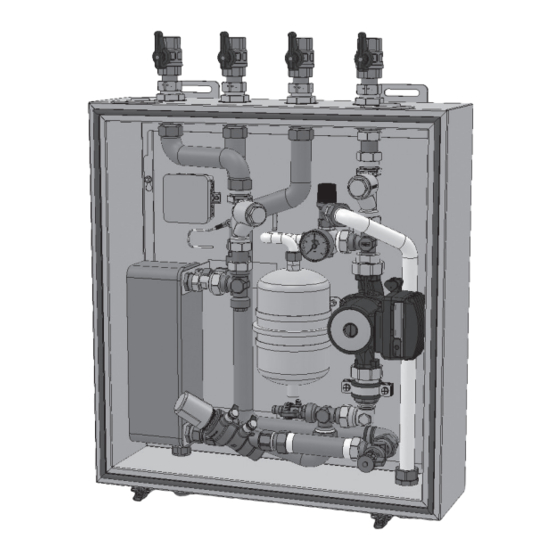
Seite 8: Aufbau Und Komponenten
3.2 Aufbau und Komponenten Bauteile Bemerkung Passstück 1" AG x 130 mm für für optionale Kältezähler (auch mit M-Bus Kompaktwärme-/Kältezähler möglich) Edelstahl-Plattenwärmeübertrager S-Line LogoCool 1-5kW : 36 Platten S-Line LogoCool 2-12kW : 36 Platten S-Line LogoCool 5-16kW : 60 Platten M-Line LogoCool 9-24kW : 50 Platten KFE-Hahn ½"... -
Seite 9: Hydraulisches Schema
Hydraulisches Schema Beispieldarstellung anhand der S-Line und M-Line LogoCool Anschlüsse und Nennweiten Vorlauf Primär Rücklauf Primär S-Line LogoCool 1" AG Vorlauf Sekundär M-Line LogoCool 2" AG Rücklauf Sekundär Sicherheitsventil Überdruckleitung 1“... -
Seite 10: Montage
3.3 Montage Bitte beachten Sie bei der Montage die genannten Sicherheitshinweise und die zusätzlichen Montagehinweise auch weiterer Komponenten! Unsachgemäße Montage und Betrieb der Stationen schließt alle Gewährleistungsansprüche aus. S-Line M-Line Montagemöglichkeiten: wandhängend mit Kühlgehäuse Wenn Sie das Gerät montieren, stellen Sie sicher, dass ausreichend Platz für Anbindung der Rohrleitungen und ele- ktrischen Kabel vorhanden ist. - Seite 11 Abmessungen und Anschlüsse der Station, sowie Maße des Kühlgehäuses S-Line M-Line M-Line S-Line Die Wand muss stabil genug sein, um das Gerät zu tragen. Die Station kann mittels der zwei oberen Laschen der S-Line Version sowie der zwei oberen und 2 unteren Laschen bei der M-Line Version an die Wand montiert werden.
-
Seite 12: Fronthaube Und Gehäuse
3.4 Fronthaube und Gehäuse Das Gehäuse inkl. der Fronthaube ist ein geschlossenes und isoliertes (30 mm Dicke) Hybrid ‐Gehäuse in mehrs- chaliger Bauform, welches eine effektive Abschirmung zur Umgebung (und deren Raumtemperatur und –feuchte) darstellt, um zusätzliche Kondensation zu vermeiden. Die Abdichtung der Fronthaube erfolgt durch die umlaufen- de Hohlkammerdichtung. -
Seite 13: Elektrischer Anschluss
3.5 Elektrischer Anschluss Die Verbindung zum Zonenventil und zur Umwälzpumpe ist bereits in der Station vorhanden. Um die Station an die Steuerung/ Timer anzuschließen, verwenden Sie ein 3-Leiter-Kabel (L, N, PE). Es ist auf eine fachgerechte Kabelverlegung zu achten, damit ein Eindringen von Feuchtigkeit in die Station vermieden wird. -
Seite 14: Einzelne Komponenten Der Stationen
4. Einzelne Komponenten der Stationen 4.1 Umwälzpumpe HE -Umwälzpumpe, Typ Grundfos UPMXL 25/125 (bzw. 25/105 bei 1-5 kW) 180 AUTO, drehzahlgesteuert Die Pumpe verfügt über einen integrierten • Motorschutz, der Überhitzung verhindert Je nach Modell können verschiedene Modi • ausgewählt werden: Die Pumpe wird intern gesteuert, mit drei •... - Seite 15 Elektrische Daten, 230 V / 50 Hz 25-105 180 AUTO (25-125 180 AUTO), EET ≤ 0,23 EuP Ready Speed P1 (W) l1/1 (A) Min. 15 (20) 0,14 (0,2) 180 (180) 1,4 (1,4) Abmessungen und Anschlüsse: Abmessungen (mm) Anschlüsse G 1½...
-
Seite 16: Druckunabhängiges Regulierventil
4.2 Druckunabhängiges Regulierventil Volumenstromregler: Ballorex Dynamic je nach Station, S-Line LogoCool 1-5 kW DN15 S 90-450 l/h Farbcode: rot S-Line LogoCool 2-12 kW DN15 H 300-1400 l/h Farbcode: schwarz S-Line LogoCool 5-16 kW DN20 H 835-2221 l/h Farbcode: schwarz M-Line LogoCool 9-24 kW DN25H 1.400-3400 l/h Farbcode: schwarz Das Ballorex Dynamic Ventil ist eine Kombination aus druckunabhängigem Durchflussbegrenzer... - Seite 17 Durchflussdiagramme Ballorex Dynamic: siehe Kap. 6.3 Hinweise: Ist ein entsprechender Kältezähler verbaut, kann die Durchflussrate dort angezeigt werden. Alternativ kann ein Messcomputer, wie der Ballorex Flowmeter BC2 für die Anzeige verwendet werden Zusätzlich zu den Ballorex-Ventilen und deren Komponenten bitte entsprechende separate Technische Informationen und Dokumentationen beachten!
-
Seite 18: Schmutzfänger
4.3 Schmutzfänger Die Schmutzfänger an den Anschluss-Eingängen der Station schützen die Anlage vor Schlamm und Verunreinigungen. Dieser kann durch Öffnen der Verschlussverschraubung ausgespült wer- den. Davor ist die Station drucklos zu schalten. Die Schmutzfänger sind mit O-Ringen abgedichtet. Beim Schließen des Schmutzfängers auf die richtige Lage des O-Rings achten. -
Seite 19: Sicherheitsventil Und Manometer
4.4 Sicherheitsventil und Manometer Beispieldarstellung anhand der S-Line LogoCool Der sekundäre Kühlkreis ist mit einem Überdruckventil 3 bar und Manometer aus- gestattet. Die Abblaseleitung ist durch das Gehäuse bereits nach außen geführt. -
Seite 20: Montage Eines Kältezählers (Optional)
4.5 Montage eines Kältezählers (optional) Vorgehensweise: 1. Alle Absperrarmaturen (primär Kreis) „A“ der Station schließen (Kugelhähne als optionales Zubehör). 2. Durch Öffnen der Entleerungsmöglichkeiten „B“ Anlagendruck absenken. 3. Verschraubungen am Passstück „C“ lösen. ACHTUNG: evtl. Medienaustritt. (Über ggf. vorhandene KFE-Hähne kann die Station entleert werden.) 4. -
Seite 21: Inbetriebnahme
5. Inbetriebnahme 5.1 Spülen und Befüllen Vor dem Befüllen ist die Anlage sorgfältig zu spülen. Alle Verbindungen sind zu kontrollieren und gegebenenfalls nachzuziehen. Verschraubungen sind beim Nachziehen sicher zu kontern. Nach dem Befüllen der Anlage ist die Station zu entlüften und die Kühlanlage ggf. nachzufüllen. Vor dem Schließen des Gehäuses ist das Silikat Kissen aus dem PE-Beutel zu nehmen und in die Station zu legen. -
Seite 22: Auslegungsdiagramme
6. Auslegungsdiagramme (für Medium: Wasser) 6.1 Druckverluste Primär-/Sekundärseite Druckverlust der Geräte- in Abhängigkeit vom Volumenstrom* Primärseite der Version S-Line Legende: Kurve 1) für die 1 bis 5 kW Einheit mit Ballorex Dynamic Kurve 2) für die 2 bis 12 kW Einheit mit Ballorex Dynamic Kurve 3) für die 1 bis 5 kW Einheit und für die 2 bis 12 kW Einheit mit Passstück für Ballorex Dynamic Kurve 4) für die 5 bis 16 kW Einheit mit Ballorex Dynamic Kurve 5) für die 5 bis 16 kW Einheit mit Passstück für Ballorex Dynamic... - Seite 23 Druckverlust der Geräte- in Abhängigkeit vom Volumenstrom Primärseite der Version M-Line ohne Dynamic. Druckverlust der Geräte- in Abhängigkeit vom Volumenstrom mit Primärseite der Version M-Line Dynamic.
- Seite 24 Druckverlust der Geräte-Sekundärseite der M-Line Version in Abhängigkeit vom Volumenstrom* ohne Pumpe Volumenstrom-Druckverlust-Diagramm* CIU 20 kW Sekundär 0,30 0,25 0,20 0,15 0,10 0,05 0,00 1000 1200 1400 1600 1800 2000 2200 2400 2600 2800 3000 Volum enstrom [l/h] *Passstück Pumpe...
-
Seite 25: Restförderhöhendiagramme Sekundärseite
6.2 Restförderhöhendiagramme Sekundärseite mit Grundfos Pumpe UPMXL Auto 25-105 (180) S-Line Kühlübergabestation 1-5 kW, Restförderhöhe - CIU MGB01300 (S-Line) mit GF UPMXL 25-125 180 Restförderhöhe - CIU 2-12 kW (S-Line) mit GF UPMXL 25-125 180 mit Grundfos Pumpe UPMXL Auto 25-125 (180) S-Line Kühlübergabestation 2-12 kW, Konstantdruck Stufe 3 Konstantdruck Stufe 2... - Seite 26 Restförderhöhe - CIU MGB01290 (S-Line) mit GF UPMXL 25-125 180 S-Line Kühlübergabestation 5-16kW, mit Grundfos Pume UPMXL Auto 25-125 (180) Restförderhöhe - CIU 5-16 kW (S-Line) mit GF UPMXL 25-125 180 Konstantdruck Stufe 3 Konstantdruck Stufe 2 Konstantdruck Stufe 1 Proportionaldruck Stufe III Proportionaldruck Stufe II Proportionaldruck Stufe I...
-
Seite 27: Volumenströme Und Kühlleistungen
6.3 Volumenströme und Kühlleistungen 6.3.1 S-Line LogoCool 1-5 kW Einheit Kühlübergabestation 1-5 kW Kühlübergabestation 3 kW Pegler 2015 Kühlleistung und Volumenströme bei unterschiedlichen Vorlauftemperaturen der Primärseite in Abhängigkeit zur Kühlleistung und Volumenströme bei unterschiedlichen Vorlauftemperaturen der Primärseite in Abhängigkeit zur Sekundärtemperatur von 14°C auf 8°C (6 Kelvin) Sekundärtemperatur von 14°C auf 8°C (6 Kelvin) Kühleistung [kW] Rücklauftemperatur der Primärseite:... - Seite 28 Kühlübergabestation 1-5 kW Kühlübergabestation 3 kW Pegler 2015 Kühlleistung und Volumenströme bei unterschiedlichen Vorlauftemperaturen der Primärseite in Abhängigkeit zur Kühlleistung und Volumenströme bei unterschiedlichen Vorlauftemperaturen der Primärseite in Abhängigkeit zur Sekundärtemperatur von 14°C auf 10°C (4 Kelvin) Sekundärtemperatur von 14°C auf 10°C (4 Kelvin) Kühleistung [kW] Rücklauftemperatur der Primärseite: bei 5°C Primär-Vorlauftemperatur ->...
- Seite 29 Kühlübergabestation 1-5 kW Kühlübergabestation 3 kW Pegler 2015 Kühlleistung und Volumenströme bei unterschiedlichen Vorlauftemperaturen der Primärseite in Abhängigkeit zur Kühlleistung und Volumenströme bei unterschiedlichen Vorlauftemperaturen der Primärseite in Abhängigkeit zur Sekundärtemperatur von 16°C auf 10°C (6 Kelvin) Sekundärtemperatur von 16°C auf 10°C (6 Kelvin) Kühleistung [kW] Rücklauftemperatur der Primärseite: bei 5°C Primär-Vorlauftemperatur ->...
- Seite 30 Für 1-5 kW Einheit, Primärseitig, Durchflussdiagramm Strangregulierventil: Ballorex Dynamic DN15 S IG/IG...
-
Seite 31: S-Line Logocool 2-12 Kw Einheit
6.3.2 S-Line LogoCool 2-12 kW Einheit Kühlübergabestation 2-12 kW Kühlübergabestation 6 kW Pegler 2015 Kühlleistung und Volumenströme bei unterschiedlichen Vorlauftemperaturen der Primärseite in Abhängigkeit zur Kühlleistung und Volumenströme bei unterschiedlichen Vorlauftemperaturen der Primärseite in Abhängigkeit zur Sekundärtemperatur von 14°C auf 8°C (6 Kelvin) Sekundärtemperatur von 14°C auf 8°C (6 Kelvin) Kühleistung [kW] 10,1 10,5 10,8... - Seite 32 Kühlübergabestation 2-12 kW Kühlübergabestation 6 kW Pegler 2015 Kühlleistung und Volumenströme bei unterschiedlichen Vorlauftemperaturen der Primärseite in Abhängigkeit zur Kühlleistung und Volumenströme bei unterschiedlichen Vorlauftemperaturen der Primärseite in Abhängigkeit zur Sekundärtemperatur von 14°C auf 10°C (4 Kelvin) Sekundärtemperatur von 14°C auf 10°C (4 Kelvin) Kühleistung [kW] 1250 1200...
- Seite 33 Kühlübergabestation 2-12 kW Kühlübergabestation 6 kW Pegler 2015 Kühlleistung und Volumenströme bei unterschiedlichen Vorlauftemperaturen der Primärseite in Abhängigkeit zur Kühlleistung und Volumenströme bei unterschiedlichen Vorlauftemperaturen der Primärseite in Abhängigkeit zur Sekundärtemperatur von 16°C auf 10°C (6 Kelvin) Sekundärtemperatur von 16°C auf 10°C (6 Kelvin) Kühleistung [kW] 10,1 10,8...
- Seite 34 Für 2-12 kW Einheit, Primärseitig, Durchflussdiagramm Strangregulierventil: Ballorex Dynamic DN15 H IG/IG...
-
Seite 35: S-Line Logocool 5-16 Kw Einheit
6.3.3 S-Line LogoCool 5-16 kW Einheit Kühlübergabestation 5-16 kW Kühlübergabestation 12 kW Pegler 2015 Kühlleistung und Volumenströme bei unterschiedlichen Vorlauftemperaturen der Primärseite in Abhängigkeit zur Kühlleistung und Volumenströme bei unterschiedlichen Vorlauftemperaturen der Primärseite in Abhängigkeit zur Sekundärtemperatur von 14°C auf 8°C (6 Kelvin) Sekundärtemperatur von 14°C auf 8°C (6 Kelvin) Kühleistung [kW] 10,1... - Seite 36 Kühlübergabestation 5-16 kW Kühlübergabestation 12 kW Pegler 2015 Kühlleistung und Volumenströme bei unterschiedlichen Vorlauftemperaturen der Primärseite in Abhängigkeit zur Kühlleistung und Volumenströme bei unterschiedlichen Vorlauftemperaturen der Primärseite in Abhängigkeit zur Sekundärtemperatur von 14°C auf 10°C (4 Kelvin) Sekundärtemperatur von 14°C auf 10°C (4 Kelvin) Kühleistung [kW] 10,0 10,5...
- Seite 37 Kühlübergabestation 5-16 kW Kühlübergabestation 12 kW Pegler 2015 Kühlleistung und Volumenströme bei unterschiedlichen Vorlauftemperaturen der Primärseite in Abhängigkeit zur Kühlleistung und Volumenströme bei unterschiedlichen Vorlauftemperaturen der Primärseite in Sekundärtemperatur von 16°C auf 10°C (6 Kelvin) Abhängigkeit zur Sekundärtemperatur von 16°C auf 10°C (6 Kelvin) Kühleistung [kW] 10,1 10,8...
- Seite 38 Für 5-16 kW Einheit, Primärseitig, Durchflussdiagramm Strangregulierventil: Ballorex Dynamic DN20H IG/IG...
- Seite 39 6.3.4 M-Line LogoCool 9-24 kW Kühlübergabestation 9-24 kW Kühlübergabestation 20 kW Pegler 2016 Kühlleistung und Volumenstrome bei unterschiedlichen Vorlauftemperaturen der Primärseite in Abhängigkeit zur Kühlleistung und Volumenströme bei unterschiedlichen Vorlauftemperaturen der Primärseite in Sekundärtemperatur von 14°C auf 8°C (6 Kelvin). Abhängigkeit zur Sekundärtemperatur von 14°C auf 8°C (6 Kelvin) Kühleistung [kW] 11,2...
- Seite 40 Kühlübergabestation 9-24 kW Kühlleistung und Volumenstrome bei unterschiedlichen Vorlauftemperaturen der Primärseite in Abhängigkeit zur Sekundärtemperatur von 14°C auf 10°C (4 Kelvin). Kühlübergabestation 20 kW Pegler 2016 Kühlleistung und Volumenströme bei unterschiedlichen Vorlauftemperaturen der Primärseite in Abhängigkeit zur Sekundärtemperatur von 14°C auf 10°C (4 Kelvin) Kühleistung [kW] 15,8 10,2...
- Seite 41 Kühlübergabestation 9-24 kW Kühlleistung und Volumenstrome bei unterschiedlichen Vorlauftemperaturen der Primärseite in Abhängigkeit zur Kühlübergabestation 20 kW Pegler 2016 Kühlleistung und Volumenströme bei unterschiedlichen Vorlauftemperaturen der Primärseite in Sekundärtemperatur von 16°C auf 10°C (6 Kelvin). Abhängigkeit zur Sekundärtemperatur von 16°C auf 10°C (6 Kelvin) Kühleistung [kW] 11,2 12,6...
- Seite 42 Kühlübergabestation 9-24 kW Für 9-24 kW Einheit, Primärseitig, Durchflussdiagramm Strangregulierventil: Ballorex Dynamic DN25 H IG/IG...