Viessmann 5238 Gebrauchsanleitung
Lastgeregelter lokdecoder
Inhaltsverzeichnis
Gebrauchsanleitung
Manual
Lastgeregelter Lokdecoder
Load controlled mobile decoder
5238
1.
Wichtige Hinweise ......................................
2.
Inhalt ..........................................................
3.
Funktionen ..................................................
4.
Einbau und Anschluss ................................
5.
Programmierung ........................................
6. Konfigurationsvariablen (CV) ..................... 1 0
7
Betrieb ........................................................
8.
Fehlersuche & Abhilfe ................................
9.
Hinweise .....................................................
10. Technische Daten ......................................
1.
Important Information .................................
2.
Content .......................................................
3.
Functions ....................................................
4.
Mounting and Connections ........................
5.
Programming ..............................................
6. Configuration variables (CV) ...................... 1 0
7.
Using the decoder ......................................
8. Checklist ..................................................... 1 5
9.
Information .................................................
10. Technical Data ...........................................
All manuals and user guides at all-guides.com
2
2
2
5
9
14
15
16
16
2
2
2
5
9
14
16
16
Inhaltsverzeichnis

Verwandte Anleitungen für Viessmann 5238


Inhaltszusammenfassung für Viessmann 5238
-
Seite 1: Inhaltsverzeichnis
All manuals and user guides at all-guides.com Gebrauchsanleitung Manual Lastgeregelter Lokdecoder Load controlled mobile decoder 5238 Wichtige Hinweise ........Inhalt ............Funktionen ..........Einbau und Anschluss ........ Programmierung ........6. Konfigurationsvariablen (CV) ..... 1 0 Betrieb ............Fehlersuche & Abhilfe ........ -
Seite 2: Wichtige Hinweise
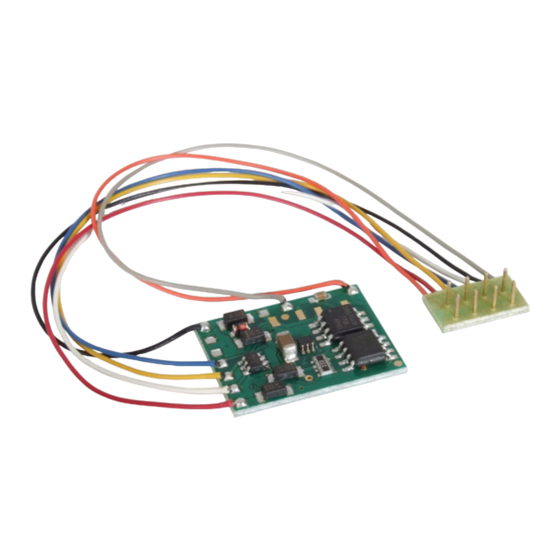
Decoder nicht, bevor Sie sich „entladen“ haben. touch components without first discharging your- Dazu reicht z.B. ein Griff an einen Heizkörper. self. Touching a radiator or other grounded metal part will discharge you. Packungsinhalt überprüfen Checking the package contents Kontrollieren Sie nach dem Auspacken den Lieferumfang auf Vollständigkeit: Check the contents of the package for completeness af- ► Decoder 5238 mit Anschlusskabel ter unpacking: und NEM 652-Stecker, ► Decoder 5238, with connecting wires and NEM 652 interface connector, ► diese Anleitung. ► this manual. Produktionsbedingt kann es vorkommen, dass die Platine nicht komplett bestückt ist. Dies ist kein Mangel. N.B. For technical reasons it is possible that the PCB is not completely inserted. This is not a fault. 3. Funktionen 3. -
Seite 3: Ansteuerung Im Analogbetrieb
Programming the decoder is done in DCC format by set- Die Programmierung des Decoders erfolgt für das DCC- ting the configuration variables and in Motorola format Format über die Einstellung der Konfigurationsvariablen through the registers. (DCC-konform), für das Motorola-Format über Register. Operation in analogue mode Ansteuerung im Analogbetrieb The locomotive decoder 5238 can also be used in ana- Den Lokdecoder 5238 können Sie auch in analogen Mo- logue model railway layouts. It can be run with an A.C. dellbahnanlagen einsetzen. Sie können ihn sowohl mit speed control as well as with a D.C. speed control. When putting the vehicle on the rails the decoder recognizes einem Wechselstrom- als auch mit einem Gleichstrom- Fahrregler betreiben. Sobald Sie das Fahrzeug auf das automatically if it is run in analogue or digital mode and Gleis stellen, erkennt der Decoder automatisch, ob er sets the corresponding operation mode. The automatic analog oder digital angesteuert wird, und stellt den ent- recognition of the analogue mode can be switched off. -
Seite 4: Funktionsausgänge
All manuals and user guides at all-guides.com Lastregelparameter: Drei Parameter bestimmen die Parameters of the load control: The load control is Lastregelung. Diese müssen aufeinander abgestimmt determined by three parameters which have to be coordi- sein, um optimale Fahreigenschaften zu erzielen. Jedem nated in order to achieve optimal driving characteristics. Lastregelparameter ist eine CV zugeordnet. Die Parame- Each of the load control parameters is assigned to a con- ter sind: figuration variable. The parameters are: KP: Der proportionale Bestandteil der Regelung sorgt da- KP: The proportional component of the load control en- für, dass der Unterschied zwischen dem Soll- und dem sures the difference between the set and the present Istwert möglichst klein wird. Er kann niemals den Wert „0“ value being as small as possible. It cannot have the value annehmen. Dieser Bestandteil wirkt sich auf die Grund- “0” at any time. This component affects the basic speed. geschwindigkeit aus. Ist der eingestellt Wert zu klein, In case the set value is too small the locomotive runs too fährt die Lok zu langsam. Ist der Wert zu groß, ruckelt die slowly. In case the set value is too high the locomotive vibrates while moving. Lok während der Fahrt. KI: Der integrale Anteil der Regelung sorgt dafür, dass KI: The integral component of the load control ensures der verbleibende Unterschied zwischen dem Soll- und the remaining difference between the set and the present dem Istwert auf 0 reduziert wird und damit dafür, dass... -
Seite 5: Einbau Und Anschluss
Feedback with RailCom lichter lassen sich einstellen. Anwendungsbeispiel: Ein- RailCom is a log for bi-directional communication in dig- ® zel- und Wechsel b linklichter oder Strobe (Aufblitzen). ital model railway layouts controlled in DCC-format. It al- Fahrtrichtungsabhängiges Schalten: Jeder Ausgang lows e.g. the feedback of the address and the CV values kann so programmiert werden, dass er in Abhängigkeit from the decoder to the digital control unit or to special von der Fahrtrichtung geschaltet wird. receivers (so-called detectors). The decoders must be designed to send the RailCom messages. Rückmeldung mit RailCom ® The decoder 5238 sends (continuously) the (basic, ex- RailCom ist ein Protokoll zur bidirektionalen Kommuni- ® tended or consist) address to the detectors (so-called kation in digitalen Modellbahnanlagen, die im DCC-For- RailCom broadcast datagramm) and transfers a CV mes- mat gesteuert werden. Es ermöglicht z. B. die Rückmel- sage after a DCC CV read-out command. dung der Adresse und der CV-Einstellungen von den De- Sending RailCom messages is only possible in layouts codern zur Digitalzentrale oder zu speziellen Empfänger- with a DCC signal on the rails. That is the reason why bausteinen (Detektoren). Die Decoder müssen die soge- it is not possible to use the RailCom-function in a pure nannten RailCom-Messages senden können. -
Seite 6: Markierung
Rail collector left Rail collector right Schienenabnehmer rechts Motorausgang (bis 1 A) grey Motor (max. 1 A) grau Motorausgang (bis 1 A) Motor (max. 1 A) orange orange Ein hilfreiches Zubehör für den Einbau von Lokdecodern The outputs for an optional smoothing capacitor have sol- ist das Viessmann Lokdecoder-Einbauset (Art. 6819). Es dering pads. If you would like to use these outputs, con- enthält Klebepads, Schrumpfschlauchstücke, passende nect the capacitor (Elko, 100 μF / 35 V) to the decoder by Kabel, Lötzinn und eine Lötanleitung. soldering the cables to the appropriate soldering pads. Pay attention to the correct polarity. Die Ausgänge für einen optionalen Stützkondensator sind mit Lötpads ausgestattet. Sollten Sie diese Ausgänge Mounting in locos with interface nutzen wollen, löten Sie einen Elektrolytkondensator (100 as per NEM 652 μF / 35 V) mit passenden Kabeln direkt an den Decoder Follow the connection diagram fig. 1. an. Beachten Sie die Polarität des Elko. -
Seite 7: Einbau In Loks Ohne Nem 652-Schnittstelle
All manuals and user guides at all-guides.com Dabei muss sich der rote bzw. orange Anschlussdraht The decoder should be put into the place designated for auf der Seite befinden, an der neben der Schnittstel- the decoder by the loco manufacturer. Is there no specific lenbuchse eine Markierung auf der Schaltplatine der place, you can place the decoder in the roof area or in Lok zu finden ist (häufig ein „*“ oder „+“). the driver’s cab. Bringen Sie den Decoder in dem vom Lokhersteller vor- Insulate all metal parts close to the decoder but don’t gesehenen Einbauplatz unter. Ist dieser Platz nicht vor- wrap the decoder with insulation tape to avoid overheat- handen, so können Sie den Decoder auch im Dachbe- ing. Otherwise the decoder may be thermally overloaded. If necessarry fix the decoder with a double sided adhe- reich oder im Führerstand montieren. sive pad. Kleben Sie in der Nähe befindliche Metallteile mit Iso- lierband ab. Befestigen Sie den Decoder falls nötig mit Mounting in locos without interface einem Klebepad. as per NEM 652 Decoder nicht in Isolierband einwickeln, da es die Wärme- Before you start, completely insulate the motor and its abfuhr behindert und zu thermischer Überlastung führt. - Seite 8 All manuals and user guides at all-guides.com Wenn der Rückleiter des Zusatzgerätes bereits mit Fahr- one side to vehicle ground, the connection is complete. zeugmasse verbunden ist, ist der Anschluss damit fer- If not, connect the second side of the lamp or the acces- tiggestellt. Andernfalls schließen Sie den jeweiligen Rück- sory to the return conductor of the decoder (point COM). leiter der Lampen und Zusatzgeräte an den Rückleiter für alle Funktionen des Decoders (Punkt COM) an. Caution: short-circuit! If you connect the accessories to the return con- Achtung, Kurzschlussgefahr! ductor for all functions (point COM), the acces- Wenn Sie die Zusatzgeräte an den Rückleiter für sories must be insulated. The accessories should alle Funktionen (Punkt COM) anschließen, müs- not make contact with metal parts of the vehicle. sen Sie sie isolieren. Die Zusatzgeräte dürfen kei- Possible short circuit! The decoder will be dam- nen Kontakt zu Metallteilen des Fahrzeugs haben. aged in operation. Kurzschlussgefahr! Der Decoder wird bei Inbe- Caution: short-circuit! triebnahme zerstört. The return conductor for all functions (point COM) Achtung, Kurzschlussgefahr! must under no circumstances be connected to ve- Der Rückleiter für alle Funktionen (Punkt COM) hicle ground. Possible short circuit! The decoder darf auf keinem Fall mit Fahrzeugmasse verbun- will be damaged in operation.
-
Seite 9: Programmierung
All manuals and user guides at all-guides.com Abb. 2 Fig. 2 Kondensator Capacitor ELKO- ELKO+ AUX 2 AUX 1 5. Programmierung 5. Programming Bevor Sie mit dem Programmieren des Lokdecoders be- Before starting to program the locomotive decoder you ginnen, muss der Motor an den Decoder angeschlossen should connect the motor to the decoder. Otherwise there sein, da sonst keine Rückmeldung zur (DCC-) Zentrale is no confirmation signal from the (DCC-) central unit. erfolgen kann. Should you intend to program the decoder with a Mo- Wenn Sie den Decoder mit einer Motorola-Zentrale pro- torola central unit you should always connect the lighting grammieren wollen, sollten Sie an die Ausgänge AUX1 to the outputs AUX1 and AUX2. The locomotive indicates und AUX2 Beleuchtungen anschließen, da die Lok den the change-over to the programming mode and the tak- ing-over of settings by flashing of the lighting connected Wechsel in den Programmiermodus und die Übernahme der Eingaben durch das Blinken der Beleuchtung an die- to these outputs. -
Seite 10: Konfigurationsvariablen (Cv)
Auswählen einer Lokadresse an Ihrer Zentrale ► lighting flashes faster: entry of a CV´s value bestä tigen. In order to stop the programming mode push “stop”. Die Beleuchtung zeigt an, welche Eingabe der Decoder erwartet: 6. Configuration variables (CV) ► Beleuchtung blinkt: Eingabe einer Registernummer The following list shows all configuration variables (for the ► Beleuchtung blinkt schneller: Eingabe des Wertes DCC format) and registers (for the Motorola format), that eines Registers. can be set for the decoder 5238. Zum Beenden des Programmiermodus drücken Sie „Stop“. In the list you will find in the column “CV-no.” the num- bers of the configuration variables for programming in 6. Konfigurationsvariablen (CV) DCC format and in the column “Reg.-no.” the numbers In der nachfolgenden Tabelle sind alle Konfigurations- of the registers for programming in Motorola format. The variablen (für das DCC-Format) und Register (für das defaults are those values set in the state of delivery and Motorola-Format) aufgeführt, die für den 5238 eingestellt after a reset. - Seite 11 All manuals and user guides at all-guides.com For some configuration variables, the input values have Hinweis: Für einige Konfigurationsvariablen werden die Eingabewerte durch Addieren der Zahlenwerte ermittelt, to be calculated by adding the numerical values assigned die den gewünschten Einstellungen entsprechen. to the desired parameters. Name der CV CV-Nr. Reg.Nr. Eingabewerte Erläuterungen / Hinweise Notice (Default) Name of CV Reg# value range Basisadresse / 1 ... 255 (3) Wertebereich bei DCC: 1 ... 127 Range of values in DCC: 1 ... 127 Basic-address Hinweis: Wenn für die Basisadresse...
- Seite 12 All manuals and user guides at all-guides.com Name der CV CV-Nr. Reg.Nr. Eingabewerte Erläuterungen / Hinweise Notice (Default) Name of CV Reg# value range Konfiguration 1 / 0 ... 64 (14) Fahrtrichtung Standard = 0 ; Direction “Standard” = 0; Configuration 1 Fahrtrichtung invertieren = 1 ; Reverse direction = 1; 14 Fahrstufen = 0 ; 28 oder 128 14 speed levels = 0; 28 or 128 Fahrstufen = 2 ; Analogerkennung speed levels = 2; Analoge recogni- aus = 0 ; Analogerkennung ein = 4 tion off = 0; Analoge recognition on ; RailCom aus = 0 ; RailCom ein = = 4; RailCom off = 0; RailCom on = 8 ; lineare Geschwi.kennlinie = 0 ; 8; Linear velocity characteristic = 0;...
- Seite 13 All manuals and user guides at all-guides.com Name der CV CV-Nr. Reg.Nr. Eingabewerte Erläuterungen / Hinweise Notice (Default) Name of CV Reg# value range Dimmen: / Dimming Reduzierung der Spannung, die Reduction of the voltage applied AUX 1, AUX 2 1 ... 255 (0) am Ausgang anliegt. Der Wert “1” to the output. The value “1” cor- ent s pricht der kleinsten, “15” der responds to the lowest, “15” to the maximum voltage. maximalen Spannung. Für jeden der Ausgänge kann ein Wert zwischen 0 und 15 It is possible to choose a value between 0 and 15 for any of the outputs. For the outputs with an odd number the value is set directly, for the outputs gewählt werden.
-
Seite 14: Betrieb
All manuals and user guides at all-guides.com Name der CV CV-Nr. Reg.Nr. Eingabewerte Erläuterungen / Hinweise Notice (Default) Name of CV Reg# value range 0 ... 64 (0) Ermöglicht die Eingabe von Werten > Allows input of values > 80 with Hilfsregister für 80 bei Zentralen, die lediglich Einga- command stations, which allow only Programmierung mit MM-Zentralen ben von 0 bis 80 zulassen. inputs from 0 - 80. Der in Register #62 eingegebene Wert multipliziert mit 4 The value in register #62 multiplied with 4 will be added to the value of the wird zum Wert des zu programmierenden Registers hinzu- programmed register. Example: Input of “137” in register #09: 1. 137 / 4 = 34, rest 1; addiert. -
Seite 15: Fehlersuche & Abhilfe
Format angesteuert wird. 8. Trouble shooting 8. Fehlersuche & Abhilfe Every Viessmann-product is manufactured under high Jedes Viessmann-Produkt wird unter hohen Qualitäts- quality standards and is tested before delivery. If there is standards gefertigt und vor seiner Auslieferung geprüft. a fault nevertheless, you can do a first check. Sollte es dennoch zu einer Störung kommen, können Sie Parts are getting very hot and/or start to smoke. anhand der folgenden Punkte eine erste Überprüfung ► Disconnect the system from the mains immediately! -
Seite 16: Hinweise
The person who brings the circuit into operation is the Gehäuseeinbau betriebsbereit macht, gilt als Hersteller manufacturer of the product. If he sells the product to und ist verpflichtet, bei der Weitergabe des Produktes another person he is responsible for passing on all the alle Begleitpapiere mitzuliefern und seinen Namen und relevant papers. seine Anschrift anzugeben. Warranty Garantiebestimmungen Every decoder is fully tested before delivery. Jeder Decoder wird vor seiner Auslieferung auf vollstän- The warranty period is 2 years from the date of purchase. dige Funktion überprüft. Der Garantie z eitraum beträgt 2 Should a failure occur during this period please contact Jahre ab Kaufdatum des Decoders. Tritt in dieser Zeit ein your dealer or Viessmann directly. Should the inspection Fehler auf, setzen Sie sich bitte direkt mit Viessmann in of the decoder indicate faulty material or workmanship Verbindung. Wird nach Überprüfung des Decoders ein then we will replace this decoder for free of charge. Herstell- oder Materialfehler festgestellt, wird Ihnen der Our warranty becomes null and void in case of damage Decoder kostenlos instand gesetzt. caused by inappropriate use of the product, disregard of Von der Garantie ausgeschlossen sind Beschädigungen the instruction manual, abnormal operating conditions, des Decoders, die durch unsachgemäße Behandlung, overload, faulty wiring (e.g. through short circuits be- Nichtbeachten der Bedienungsan l eitung, nicht bestim- tween current pick-up and motor, short circuits between mungsgemäßen Gebrauch, Überlastung, Umschaltimpuls motor output and chassis), unauthorized modifications, von analogen Wechselstromanlagen, fehlerhafte Ver- overheating, etc. .