Viessmann 5248 Gebrauchsanleitung
Lastgeregelter lokdecoder
Inhaltsverzeichnis
Gebrauchsanleitung
Manual
Lastgeregelter Lokdecoder
Load controlled mobile decoder
5248
1.
Wichtige Hinweise ......................................
2.
Inhalt ..........................................................
3.
Funktionen ..................................................
4.
Einbau und Anschluss ................................
5.
Programmierung ........................................
6. Konfigurationsvariablen (CV) ..................... 1 0
7
Betrieb ........................................................
8.
Fehlersuche & Abhilfe ................................
9.
Herstellerhinweis ........................................
10. Technische Daten ......................................
1.
Important Information .................................
2.
Content .......................................................
3.
Functions ....................................................
4.
Mounting and Connections ........................
5.
Programming ..............................................
6. Configuration variables (CV) ...................... 1 0
7.
Using the decoder ......................................
8. Checklist ..................................................... 1 5
9.
Manufacturer information ...........................
10. Technical Data ...........................................
2
2
2
6
9
15
15
16
16
2
2
2
6
9
15
16
16
Inhaltsverzeichnis

Verwandte Anleitungen für Viessmann 5248


Inhaltszusammenfassung für Viessmann 5248
-
Seite 1: Inhaltsverzeichnis
Gebrauchsanleitung Manual Lastgeregelter Lokdecoder Load controlled mobile decoder 5248 Wichtige Hinweise ........Inhalt ............Funktionen ..........Einbau und Anschluss ........ Programmierung ........6. Konfigurationsvariablen (CV) ..... 1 0 Betrieb ............Fehlersuche & Abhilfe ........ Herstellerhinweis ........10. Technische Daten ........ -
Seite 2: Wichtige Hinweise
Decoder nicht, bevor Sie sich „entladen“ haben. touch components without first discharging your- Dazu reicht z.B. ein Griff an einen Heizkörper. self. Touching a radiator or other grounded metal part will discharge you. Packungsinhalt überprüfen Checking the package contents Kontrollieren Sie nach dem Auspacken den Lieferumfang auf Vollständigkeit: Check the contents of the package for completeness af- ► Decoder 5248 mit Anschlusskabel ter unpacking: und NEM 652-Stecker, ► Decoder 5248, with connecting wires and NEM 652 ► diese Anleitung. interface connector, ► this manual. Produktionsbedingt kann es vorkommen, dass die Platine nicht komplett bestückt ist. Dies ist kein Mangel. N.B. For technical reasons it is possible that the PCB is not completely inserted. This is not a fault. 3. Funktionen 3. - Seite 3 Programming the decoder is done in DCC format by set- Die Programmierung des Decoders erfolgt für das DCC- ting the configuration variables and in Motorola format Format über die Einstellung der Konfigurationsvariablen through the registers. (DCC-konform), für das Motorola-Format über Register. Operation in analogue mode Ansteuerung im Analogbetrieb The locomotive decoder 5248 can also be used in ana- Den Lokdecoder 5248 können Sie auch in analogen Mo- logue model railway layouts. It can be run with an A.C. dellbahnanlagen einsetzen. Sie können ihn sowohl mit speed control as well as with a D.C. speed control. When putting the vehicle on the rails the decoder recognizes einem Wechselstrom- als auch mit einem Gleichstrom- Fahrregler betreiben. Sobald Sie das Fahrzeug auf das automatically if it is run in analogue or digital mode and Gleis stellen, erkennt der Decoder automatisch, ob er sets the corresponding operation mode. The automatic analog oder digital angesteuert wird, und stellt den ent- recognition of the analogue mode can be switched off.
- Seite 4 annehmen. Dieser Bestandteil wirkt sich auf die Grund- value is reduced to 0 and so for the correction of very geschwindigkeit aus. Ist der eingestellt Wert zu klein, small divergences. Is the set value is too high the loco- fährt die Lok zu langsam. Ist der Wert zu groß, ruckelt die motive vibrates massively while moving. Lok während der Fahrt. KD: The differential component of the load control en- KI: Der integrale Anteil der Regelung sorgt dafür, dass sures that the control is not converted too quickly. Is the der verbleibende Unterschied zwischen dem Soll- und set value to low then the locomotive vibrates. Is the set dem Istwert auf 0 reduziert wird und damit dafür, dass value is too high, the locomotive shakes while moving. auch sehr kleine Abweichungen ausgeregelt werden. Ist Velocity characteristic der eingestellte Wert zu groß, führt das zu starkem Ru- ckeln der Lok während der Fahrt. The decoder can be adjusted to the driving character- KD: Der differentiale Anteil der Regelung sorgt dafür, istics of the motor and the characteristic speed of the locomotive type, by setting the starting velocity and the dass die Regelung nicht zu schnell umgesetzt wird. Ist der eingestellte Wert zu niedrig, ruckelt die Lok während...
-
Seite 5: Effekte Der Funktionsausgänge
SUSI interface zweiten Decoderadresse zugeordnet werden, geschaltet A SUSI module can be connected to the decoder 5248 werden. Die Funktionen F10 bis F12 stehen im Motorola- and programmed via the decoder. It is not possible to Format nicht zur Verfügung. read the SUSI module´s data via the decoder. Die Zuordnung der Funktionstasten zu den Funktionsaus- The locomotive decoder transmits the function status and gängen des Decoders ist frei wählbar. Sie können einem the speed level set at the central unit, to the SUSI mod- Funktionsausgang mehrere Funktionstasten zuordnen. ule. This affects the SUSI module´s outputs depending on the speed level (e.g. motor sound). SUSI-Schnittstelle An den Decoder können Sie ein SUSI-Modul anschlie- Effects of the function outputs ßen, das auch über den Decoder programmiert werden It is possible to set the following effects for all function kann. Das Auslesen der Daten des SUSI-Moduls ist über outputs individually: den Decoder nicht möglich. Dimming: The voltage applied to an output can be re- Der Lokdecoder überträgt den Zustand der Funktionen duced by programming the decoder accordingly. Exam- und die an der Zentrale eingestellte Fahrstufe an das ple of use: The electric bulbs of older vehicles made for SUSI-Modul. Dadurch werden geschwindigkeitsabhän-... -
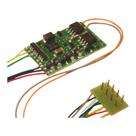
Seite 6: Einbau Und Anschluss
Das Versenden von RailCom-Messages ist nur in Anla- gen möglich, in denen ein DCC-Signal an den Schienen An useful accessory for the mounting of loco decoders is anliegt. Daher ist die Nutzung der RailCom-Funktion in the Viessmann installation set for loco decoders (#6819). einer reinen Motorola-Umgebung nicht möglich, sondern It contains all materials for trouble free installation of de- nur dann, wenn mindestens ein beliebiger anderer Deco- coders into model engines as e. g. wires, shrink sleeves, der auf der Anlage im DCC-Format angesteuert wird. adhesive pads etc. The outputs AUX 4 - 6 have soldering pads. If you would 4. Einbau und Anschluss like to use these outputs, connect the resp. functions of Prüfen Sie vor dem Einbau des Decoders, ob der the loco to the decoder by soldering the cables to the ap- propriate soldering pads. maximale Strom des Lokmotors unter Last unter- halb des maximal zulässigen Wertes von 1.000 mA liegt. Liegt der Wert oberhalb von 1.000 mA, ist dieser Decoder nicht für den Einbau in die Lok geeignet. Er würde bei Inbetriebnahme zerstört. Ein hilfreiches Zubehör für den Einbau von Lokdecodern ist das Viessmann Lokdecoder-Einbauset (Art. 6819). Es enthält Klebepads, Schrumpfschlauchstücke, passende Kabel, Lötzinn und eine Lötanleitung. -
Seite 7: Einbau In Loks Mit Nem 652-Schnittstelle
Die Ausgänge AUX 4 - 6 sind mit Lötpads ausgestattet. Mounting in locos with interface Sollten Sie diese Ausgänge nutzen wollen, löten Sie die as per NEM 652 entsprechenden Zusatzgeräte in der Lok mit passenden Follow the connection diagram fig. 1. Kabeln direkt an den Decoder an. ► Open the loco and remove the bridge plate from the Einbau in Loks mit interface socket of the loco. NEM 652-Schnittstelle ► Insert the NEM 652-connector into the interface sock- et of the locomotive. Beachten Sie den Anschlussplan in Abb. 1. Please make sure that the orange and red cables from ► Öffnen Sie die Lok und entfernen Sie den Brücken- the plug are on the side of the socket where a mark stecker aus der Schnittstellenbuchse der Lok. (often a “*” or a “+”) is printed on the circuit board. -
Seite 8: Werkseitige Decodereinstellungen
den Beleuchtungen oder andere Verbraucher mit einem are connected, or if the total current of the motor and the Strom von mehr als 500 mA an den Decoder angeschlos- accessories is higher than 1.500 mA the decoder will be sen oder beträgt der Gesamtstrom aller angeschlossenen damaged when put into operation. Verbraucher und des Motors mehr als 1.500 mA, wird der Disconnect any existing diodes in the leads to the lamps. Decoder bei der Inbetriebnahme beschädigt. Connect the lamps and the accessories to the function Entfernen Sie eventuell vorhandene Dioden in den Zulei- outputs (AUX1 to AUX6) of the decoder. The assignment tungen zu den Lampen. of the function outputs to the function keys will be made Schließen Sie die Zusatzgeräte an die Funktionsausgän- when programming the decoder. ge (AUX4 bis AUX6) des Decoders an. Die Zuordnung If the lamp or the accessory is already connected with der Ausgänge zu den Funktionstasten erfolgt während one side to vehicle ground, the connection is complete. der Programmierung des Decoders. If not, connect the second side of the lamp or the acces- Wenn der Rückleiter des Zusatzgerätes bereits mit Fahr- sory to the return conductor of the decoder (point COM). zeugmasse verbunden ist, ist der Anschluss damit fer- Caution: short-circuit! tiggestellt. Andernfalls schließen Sie den jeweiligen Rück- If you connect the accessories to the return con- leiter der Lampen und Zusatzgeräte an den Rückleiter für... -
Seite 9: Programmierung
Ausgang der Funktionsausgänge die Kathoden (-) der Caution: LEDs ange s chlossen werden. If you use light-emitting diodes (LEDs) you must Beachten Sie: always operate them via a series resistor. LEDs are available in many different models. The series Wenn Sie LEDs einsetzen, müssen Sie diese im- resistor limits the current flow of the LED and will mer über einen Vorwiderstand betreiben! Die Vor- need to be calculated for each model. Ask for the widerstände sind je nach Strom und Bauform der max. current rating when buying your LEDs. Leuchtdioden unterschiedlich. Ermitteln Sie die richtigen Werte oder erfragen Sie sie beim Kauf. You can connect several LEDs in parallel to each output. In this case every LED must have a series resistor of its Sie können mehrere LEDs an einen Ausgang parallel an- own. If you connect several LEDs to one output in series, schließen. In diesem Fall muss jede Diode einen eigenen only one series resistor is needed. Vorwiderstand erhalten. Wenn Sie mehrere LEDs an ei- nen Ausgang in Reihe anschließen, reicht ein Vorwider- Connecting a smoothing capacitor stand aus. -
Seite 10: Programmierung Mit Motorola-Zentralen
Sie pro g rammieren wollen. Um ein Register zum Pro- In order to stop the programming mode push “stop”. grammieren auszuwählen oder einen Wert für ein Regi- ster einzugeben, müssen Sie die eingebene Zahl immer 6. Configuration variables (CV) wie beim Auswählen einer Lokadresse an Ihrer Zentrale bestä tigen. The following list shows all configuration variables (for the Die Beleuchtung zeigt an, welche Eingabe der Decoder DCC format) and registers (for the Motorola format), that erwartet: can be set for the decoder 5248. ► Beleuchtung blinkt: Eingabe einer Registernummer In the list you will find in the column “CV-no.” the num- bers of the configuration variables for programming in ► Beleuchtung blinkt schneller: Eingabe des Wertes DCC format and in the column “Reg.-no.” the numbers eines Registers. of the registers for programming in Motorola format. The Zum Beenden des Programmiermodus drücken Sie „Stop“. defaults are those values set in the state of delivery and after a reset. 6. Konfigurationsvariablen (CV) In der nachfolgenden Tabelle sind alle Konfigurations- variablen (für das DCC-Format) und Register (für das... - Seite 11 gister für die Programmierung im Motorola-Format ange- For some configuration variables, the input values have geben. Die Defaultwerte sind die Werte, die bei Auslie- to be calculated by adding the numerical values assigned ferung eingestellt sind, und die nach einem Reset einge- to the desired parameters. stellt werden. Hinweis: Für einige Konfigurationsvariablen werden die Eingabewerte durch Addieren der Zahlenwerte ermittelt, die den gewünschten Einstellungen entsprechen. Name der CV CV-Nr. Reg.Nr. Eingabewerte Erläuterungen / Hinweise Notice (Default) Name of CV Reg# value range Basisadresse / 1 ... 255 (3) Wertebereich bei DCC: 1 ... 127 Range of values in DCC: 1 ... 127 Basic-address Hinweis: Wenn für die Basisadresse Tip: If a value higher than 127 is set ein höherer Wert als 127 program-...
- Seite 12 Name der CV CV-Nr. Reg.Nr. Eingabewerte Erläuterungen / Hinweise Notice (Default) Name of CV Reg# value range Mehrfach- 1 ... 127 (0) = 2nd adress 2. Adresse. traktionsadresse / Nur im DCC-Format! In DCC format only! Consist address Bremsverhalten bei 0 , 16 , 32 , Kein Bremsen bei Gleichspg. = 0 No braking with d.c. = 0 Gleichspannung / 48 (0) Bremsen bei pos. Gleichspg. = 16 Braking with positive d.c. = 16 Braking perform. Bremsen bei neg. Gleichspg. = 32 Braking with negative d.c. = 32 Hinweis: Standardmäßig wird bei Anliegen einer Gleich- Tip: It is standard to switch over into analogue mode when applying a d.c. voltage at the rails. In case that the decoder is run in a layout with a braking spannung am Gleis in den Analogbetrieb umgeschaltet.
- Seite 13 Name der CV CV-Nr. Reg.Nr. Eingabewerte Erläuterungen / Hinweise Notice (Default) Name of CV Reg# value range Konfiguration 2 / 0 ... 127 (73) Lastregelung aus = 0; Lastregelung Load control inactive = 0; Load Configuration 2 ein = 1; Rangiergang mit F1 = 2; control active = 1; Shunting gear Rangiergang mit F2 = 4; Rangiergang at F1 = 2; Shunting gear at F2 = 4; mit F3 = 8; Rangiergang mit F4 = Shunting gear at F3 = 8; Shunting 16; Anfahr- / Bremsverzögerung gear at F4 = 16; Acceleration and schaltbar mit F3 = 32; Anfahr- / brake delay to be switched at F3 = Bremsverzögerung schaltbar mit 32; Acceleration and brake delay to F4 = 64 be switched at F4 = 64 0 ... 255 (40) = Proportionaler Anteil der Last- = Proportional component of the Lastregelparam. KP Param. load control load control.
- Seite 14 Name der CV CV-Nr. Reg.Nr. Eingabewerte Erläuterungen / Hinweise Notice (Default) Name of CV Reg# value range Blinkfrequenz Licht 10 ... 255 (200) Settings common for all lighting: Einstellung für alle Blinklichter ge- Flashing frequency meinsam: 10 = niedrigste Frequenz 10 = lowest frequency and 255 = of the lighting 255 = höchste Frequenz highest frequency Beispiele für die Blinkfrequenz: Examples for the flashin frequency: CV#112 = 10 2 Hz / CV#112 = 48 0,7 Hz CV#112 = 10 2 Hz / CV#112 = 48 0,7 Hz CV#112 = 100 0,25 Hz / CV#112 = 255 0,125 Hz CV#112 = 100 0,25 Hz / CV#112 = 255 0,125 Hz 1 ... 126 (16) Fahrstufe, ab der die in CV#116 fest- Speed level, at which the outputs Fahrstufe für CV#116 / Speed defined in CV#116 are dimmed.
-
Seite 15: Betrieb
(Motorola-Format) des Lokdecoders RailCom format) of the locomotive decoder RailCom is switched ® einge- schaltet ist (s. a. Seite 6). on (refer also page 6f). RailCom-Messages can only be transferred in model 8. Fehlersuche & Abhilfe railway layouts with a DCC signal on the rails. When the locomotive decoder is operated in Motorola format, Rail- Jedes Viessmann-Produkt wird unter hohen Qualitäts- Com messages cannot be sent unless simultaneuously at standards gefertigt und vor seiner Auslieferung geprüft. least one other locomotive or function decoder is control- Sollte es dennoch zu einer Störung kommen, können Sie led in DCC-Format. anhand der folgenden Punkte eine erste Überprüfung vornehmen. 8. Trouble shooting Decoder wird sehr heiß und / oder fängt an zu qualmen. -
Seite 16: Herstellerhinweis
nicht festzustellen ist, welche Ursache die Störsignale coder anew. haben, ist es ratsam, die automatische Analogerken- In digital mode the locomotive suddenly runs very fast. nung während des Digitalbetriebs auszuschalten. ● Possible cause: Interfering signals from the layout Ein Ausgang lässt sich nicht einschalten. have switched the decoder to analogue mode. As the ● Mögliche Ursache: In den CV#53 bis 58 sind für einen origin of the interfering signals´ often cannot be found, Ausgang Werte eingestellt, die sich gegenseitig aus- it is advisable to switch off the automatic recognition schließen. Ändern Sie die Werte für CV#53 bis 58. of the analogue mode during digital operation. Lok fährt nicht im Analogbetrieb. An output cannot be switched on. ● Mögliche Ursache: Der Analogbetrieb ist ausgeschal- ● Possible cause: The values set in CV#53 to 58 for tet. Ändern Sie den Wert für CV#29.