Inhaltszusammenfassung für Vortice VORT NRG EC 3000
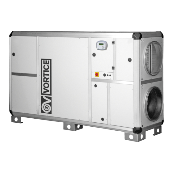
Seite 1
Operating and commissioning instructions Notice d’instructions et de mise en service Bedienungs- und Inbetriebnahmeanleitung VORT NRG EC / EC EH 3000 - 4500 - 6000 - 8000 COD. 5.471.084.691 25/05/2017...
Seite 2
Read the instructions contained in this booklet carefully before using the appliance. Vortice cannot assume any responsibility for damage to property or personal injury resulting from failure to abide by the instructions given in this booklet. Following these instructions will ensure a long service life and overall electrical and mechanical reliability.
Seite 3
VI.4.3 Terminal boards ............................17 VI.5 Connection of the motors ........................18 VORT NRG EC 4500, 6000, 8000........................18 VORT NRG EC 3000 ............................18 VI.6 Connection of pressure transmitters for MAC2 / LOBBY / QUATTRO..........19 VI.7 Connection of CO2 transmitter for DIVA / QUATTRO................19 VI.8 Bypass ..............................19...
Seite 4
ENGLISH VII SETTINGS..............................23 VII.1 Control (on CORRIGO or remote control) .....................23 VII.2 Tree structure of menus.........................27 VII.3 Modification of parameters ........................27 VII.3.1 Access to blocked parameters......................27 VII.3.2 Setting different dates and times on the clocks (password required)...........27 VII.3.2.a Date and time of the CORRIGO regulator (1) section VII.22..............27 VII.3.2.b Programming the system’s operating timetable (2) (3) section VII.2 .............27 VII.3.2.c Vacation period (4) section VII.2 ......................27 VII.3.3 Modification of speed / pressure / airflow in LS and HS (password required) ........28...
Seite 5
VI.4.4 Borniers ..............................64 VI.5 Branchement des moteurs ........................65 VORT NRG EC 4500, 6000, 8000........................65 VORT NRG EC 3000 ............................65 VI.6 Branchement des transmetteurs de pression pour MAC2 / LOBBY / QUATTRO.........66 VI.7 Branchement des transmetteurs de CO2 pour DIVA / QUATTRO............66 VI.8 By-pass ..............................66...
Seite 6
FRANÇAIS VII RÉGLAGES............................70 VII.1 / Contrôle (sur CORRIGO ou contrôle à distance) ................70 VII.2 Structure des menus en arbre.......................71 VII.3 Modification des paramètres.........................74 VII.3.1 Accès aux paramètres verrouillés......................74 VII.3.2 Programmation de plusieurs dates et horaires sur les horloges (avec mot de passe) ......74 VII.3.2.a Date et heure du régulateur CORRIGO (1) chapitre VII.22 ..............74 VII.3.2.b Programmation du calendrier des activités du système (2) (3) chapitre VII.2 ........74 VII.3.2.c Période de vacances (4) chapitre VII.2 ....................74...
Seite 7
VI.4.4 Klemmenleisten ..........................111 VI.5 Anschluss der Motoren ........................112 VORT NRG EC 4500, 6000, 8000........................112 VORT NRG EC 3000 ............................112 VI.6 Anschluss der Drucktransmitter für MAC2 / LOBBY / QUATTRO ............113 VI.7 Anschluss der CO2-Transmitter für DIVA / QUATTRO.................113 VI.8 Bypass ..............................113 VI.9 NIGHT COOLING..........................114...
Seite 8
DEUTSCH VII EINSTELLUNGEN..........................117 VII.1 / Steuerung (am CORRIGO-Regler oder Fernbedienung)..............117 VII.2 Baumstruktur der Menüs........................118 VII.3 Parameteränderungen .........................121 VII.3.1 Zugriff auf die gesperrten Parameter....................121 VII.3.2 Einstellung unterschiedlicher Daten und Uhrzeiten an den Uhren (Passwort erforderlich)....121 VII.3.2.a Datum und Uhrzeit des CORRIGO-Reglers (1) Kapitel VII.22 ............121 VII.3.2.b Programmierung des Zeitplans und der Nutzungszeiten im Zeitplan (2) (3) Kapitel VII.2 ....121 VII.3.2.c Ferienzeitraum (4) Kapitel VII.2......................121 VII.3.3 Änderung von Drehzahl/Druck/Volumenstrom bei LS und HS (Passwort erforderlich) ......122...
ENGLISH In compliance with current regulations, the machine must be installed only by a technical person qualified for this type of work. During installation, ensure that: - The machine is handled as specified in section II.1. - The required personal protection devices are worn so as to avoid injuries caused by electrical and mechanical hazards (injuries by touching panels, sharp edges, etc.).
Seite 10
ENGLISH NRG EFC 4F NRG EC RRC Installing the units on the ceiling: the units must be mounted preferably on a frame suspended from the structure of the building, taking care to comply with load limits (the frame is the installer’s responsibility). NRG EC RRC RRO For these units, provide a gradient of 2 to 3% for the removal of condensate in the direction of the width.
Seite 11
ENGLISH III.2 VORT NRG EC - EC EH (DIVA ® proportional ventilation between two airflows (LS/HS) according to concentration of CO «MODE AUTO CO » HS (high speed) Available functions • Adjustment of a minimum speed (L.S.) and a maximum speed (H.S.) in %; (the CO set-point is factory-set to 1000 ppm) LS (low speed)
Seite 12
ENGLISH IV HVAC CONNECTION Connect the unit with the help of the labels located on each port. The hoses must be heat-insulated. This should be done in accordance with best practices (no elbow on fan outlet before a minimum distance of 5 times the port diameter, etc.).
15.7 A (400 V TRI + N) VORT NRG EC 3000 6 A (230 V MONO) VORT NRG EC 3000 037 22.3 A (230 V MONO) 15.7 A (400 V TRI + N) 25.4 A (400 V TRI + N) VORT NRG EC 3000 067 7.7 A (400 V TRI + N)
Seite 14
ENGLISH VI.4 Electric board’s terminal 30 31 33 34 10 11 39 40 42 43 15 16 18 19 21 22 24 25 Control terminal Power terminal and accessories (on lower DIN rail) for fan operations (on upper DIN rail) VI.4.1 Power terminal connection Name Terminals...
Seite 15
ENGLISH VI.4.2 Control terminal connection 10 11 15 16 18 19 21 22 24 25 Control terminal (on lower DIN rail) Name Terminals Connection To be connected to terminals 1 and 2 of the motorised supply air damper DO3* (GMA 121.1E) To be connected to terminals 1 and 2 of the motorised return air damper DO4* (GMA 121.1E)
Seite 16
ENGLISH Name Terminals Connection TRPS (LOBBY MAC2 and Supply air pressure transmitter (see section VI.6) QUATTRO) Agnd* UI2* TRPS (LOBBY MAC2 and Return air pressure transmitter (see section VI.6) QUATTRO) Agnd* UI3* CO 2 (DIVA and QUATTRO) CO 2 transmitter (see section VI.7) Agnd* UI4* THS/THA or K1 auxiliary for...
Seite 17
ENGLISH VI.4.4 Terminal boards An SAF pressure contact is TH1= Outdoor temperature for heating available in the TECHNICAL recovery by exchanger (factory setting: 18°C) compartment An EAF pressure contact is TH2= Outdoor temperature for cooling available on the regulation recovery by exchanger (factory setting: 24°C) A filter guard contact is available on the terminal boards 31-32 TH3= Exhaust temperature for de-icing by...
Seite 18
ENGLISH VORT NRG EC 3000 POWER CONTROL VORT NRG EC 4500, 6000, 8000 POWER CONTROL...
Seite 19
ENGLISH VI.6 Connection of pressure transmitters for MAC2 / LOBBY / QUATTRO The pressure transmitters are factory-wired. RETURN AIR SUPPLY AIR LOBBY / MAC2 AND QUATTRO EC PRESSURE TRANSMITTER VI.7 Connection of CO transmitter for DIVA / QUATTRO The CO 2 transmitter is factory-wired VI.8 Bypass This function is automatically controlled using the CORRIGO regulator’s programming and the probes installed as standard in our VORT NRG EC units.
Seite 20
ENGLISH VI.9 NIGHT COOLING This function is used during summer to cool buildings at night by using cool outdoor air, thus reducing the cooling power to be delivered during the day. The NIGHT COOLING function works only between midnight and 7 a.m.. During the Night Cooling period, the heating and cooling outlets are blocked.
Seite 21
ENGLISH VI.13 Direct duct expansion coil (this function must be specified at the time of ordering) A maximum 24 V 2A output is provided to control the start/stop of your cold unit, to be connected between terminals DO7 and 2 (provide a relay on the condensation unit). You should also shift the supply air probe after the direct expansion coil.
Seite 22
ENGLISH VI.16 Electric defrosting coil (EH, INFINITE BE, INFINITE BC) On the EH, INFINITE BE and INFINITE BC versions, the defrosting coil is already installed in the unit. The control is also connected. COIL CAB-CBE terminal Single-phase heating coil COIL...
Seite 23
ENGLISH VI.17 Repeater (see section VII.3.8 for configuration) You must have a repeater if you want to connect: • More than one unit on the same display (maximum 6) • A remote control at more than 100 metres In this case you can move the remote control system up to 1 km away. Use a shielded twisted 2-pair cable of BELDEN 8723 type or equivalent to connect the repeater to the control housing.
Seite 24
CORRIGO E Ventilation Year:month:day Time Ventilation Version: System:start oper. or stop Made by ID number: SP: T°C set point Act.: T°C current VORTICE Operating mode Operating mode Operating mode Auto (6) . . . Operating period Vent. AS: 00.0 hours Operating period Vent.
Seite 25
ENGLISH Outdoor comp. set-point Temperature regulation Ext. temp.: -20°C = 25°C (7) Supply air temp. -15°C = 24°C (7) Actual: Set point -10°C = 23°C (7) Set point: Outdoor comp. set-point -5°C = 23°C (7) 0°C = 22°C (7) 5°C = 20°C (7) Outdoor comp.
Seite 26
ENGLISH Time: 15:54 (1) Time/date Time setting Date: 2011-01-25 (1) Day: Tuesday (1) Normal speed Normal speed Normal speed schedule Monday (2) Monday Friday (2) Per. 1: 07:00 - 12:00 Per. 1: 07:00 - 12:00 Per. 2: 14:00 - 18:00 Per.
Seite 27
ENGLISH VII.3 Modification of parameters VII.3.1 Access to blocked parameters Some parameters are blocked by a password; in this case, when you would like to modify them by pressing the OK key, this screen will appear. Enter password of the desired authorisation level Password: **** Level: Without Enter the code 3333 using the arrow keys and then confirm with the OK key.
Seite 28
ENGLISH VII.3.3 Modification of speed / pressure / airflow in LS and HS (password required) VII.3.3.a VORT NRG EC and DIVA (5) section VII.2 You can change the rotation speeds of your unit to LS (reduced speed) and HS (normal speed) for each fan in order to set your own customised airflows.
Seite 29
ENGLISH • Move the cursor to the cons. menu as described in section VII.2. Outdoor comp. set-point • Once in this menu, press the OK key. -20.0° = 25.0° • Enter the desired value. The outdoor temperature values are not -15.0°...
Seite 30
Time Ventilation Version: 3.0 System:start oper. or stop Made by ID number: SP: T°C set point Act.: T°C current VORTICE Modbus addresses: 1 (2) Modbus secondary ..Speed: 9600 Bps (3) com. 2 stop bits: Yes (4)
Seite 31
ENGLISH VII.3.8 Modification of system parameters VII.3.8.a Access to system level These parameter settings require access to the Configuration menu. For this you should get the “System” level access rights. Follow the procedure set out below. MODE OF REGULATION Year:month:day Time System:start oper.
Seite 32
ENGLISH VII.3.8.f BACNET IP type B communication To activate BACNET and change the parameters (fixed IP, name of controller…), download the appropriate E-tool software or the lightweight WEB configuration software from: http://www.regin.se (download tab) You will find the complete WEB variables list at: http://www.regin.se. VIII REPAIR VIII.1 Various examples of faults The Regulation of the VORT NRG EC units is equipped with alarms.
Seite 33
LOBBY Motor not working MAC2 The pressure read by the transmitter is less than 30Pa. (CARMA QUATTRO LOBBY, MAC2 and QUATTRO) (contact Vortice) The motor’s thermal cut-out has triggered. AR vent. fault Return air fan not 30 sec The pressure switch is wrongly connected (the pressure switch...
Seite 34
ENGLISH Description Display Type Time Cause Outdoor Outdoor temperature 5 sec The outdoor temperature probe SEG is not working or is wrongly temp. probe probe error wired (see section V) error AS temp. Supply air temperature 5 sec The supply air temperature probe SSG is not working or is wrongly probe error probe error wired (see section V)
Seite 35
ENGLISH VIII.2 Changing the battery This operation requires good knowledge of DES (electrostatic discharges and wearing a bracelet or any other earthing accessory) When the “low battery” alarm appears and the red indicator lights up, this means that the emergency battery for memory and real-time clock back-up is too weak.
ENGLISH IX MAINTENANCE • Outside of the unit: check the ducts, flexible bands and vibration dampers; replace if needed. Check that all the items linked to the unit are in place so that no vibration can be transmitted to the external items. •...
Seite 37
ENGLISH X NOTES, GRAPHS AND COMMUNICATION DIAGRAMS Date Observations...
Seite 38
ENGLISH BMS: standard - MODBUS / RS485 - WEB / TCP/IP - BACNET / TCP/IP - EXO / TCP/IP 100 metres...
Seite 39
ENGLISH REPEATER / RS485 100 metres Maximum 6 control units...
Seite 44
ENGLISH CARMA 9070 VORT NRG EC 8000 100% 1000 2000 3000 4000 5000 6000 7000 Airflow m3/h...
Seite 45
ENGLISH Introduction Corrigo E ventilation is a pre-programmed application for control of an air handling unit (CTA). The Corrigo E controller can be used either stand-alone or integrated in a EXO system. In both cases, it is configured via the display or by using the configuration tool E tool on a PC.
Seite 46
ENGLISH RS485 against RS422 RS485 and RS422 are both the electric element and the physical support of the protocol. The RS485 protocol is equipped with two connections, A and B. Very often, there is also a ground connection (N on EXO devices).
Seite 47
ENGLISH Configuration The communication parameters for the Modbus line are the most important thing to configure first. As described earlier, these parameters must be identical in both the master unit and slave units, since they define the structure of messages and the transmission speed.
ENGLISH XI INPUT REGISTER Signal name Function Description VentActual. Cor_RunMode Actual/Setpoint 0=stopped 1=starting up 2= reduced speed starting 3= full speed starting 4= normal speed starting 5= running 6= heating restart 7= cooling restart 8= C02 running 9= night cooling 10= full speed mode 11= stopping VentActual.
ENGLISH XII HOLDING REGISTER Signal name Function Description VentSetting.Cor_Curve1_Y 1 25°C Supply, extract and Supply setpoint for -20°C room temperature outdoor T°C V entSetting. Cor_Curve 1 _Y 2 24°C Supply, extract and Supply setpoint for -15°C room temperature outdoor T°C V entSetting.
Seite 50
ENGLISH Signal name Function Description TimeDp.Posts(0).T1 Timer Normal Speed Start time period 1 MONDAY normal speed (HH.MM) TimeDp.Posts(0).T2 Timer Normal Speed Stop time period 1 MONDAY normal speed (HH.MM) TimeDp.Posts(0).T3 Timer Normal Speed Start time period 2 MONDAY normal speed (HH.MM) TimeDp.Posts(0).T4 Timer Normal Speed...
Seite 51
ENGLISH Signal name Function Description TimeDp.Posts(5).T3 Timer Normal Speed Start time period 1 SATURDAY normal speed (HH.MM) TimeDp.Posts(5).T4 Timer Normal Speed Stop time period 1 SATURDAY normal speed (HH.MM) TimeDp.Posts(6).T1 Timer Normal Speed Start time period 1 SUNDAY normal speed (HH.MM) TimeDp.Posts(6).T2 Timer Normal Speed...
ENGLISH XIII INPUT STATUS REGISTER Signal name Function Description QDig.DI1 Digital input Si 1 = The supply pressure switch indicates the fan operation QDig.DI2 Digital input Si 1 = The recovery pressure switch indicates the fan operation QDig.DI3 Digital input Si 1 = dirty filter QDig.DI4 Digital input...
Seite 53
ENGLISH Signal name Function Description VentAtcual. Cor_AlaPt(41 ) Alarm point Heating control in manual mode 0 = No alarm VentAtcual. Cor_AlaPt(42) Alarm point Cooling control in manual mode 0 = No alarm VentAtcual. Cor_AlaPt(43) Alarm point Exchanger control in manual mode 0 = No alarm VentAtcual.
Seite 55
Vortice Elettrosociali S.p.A. reserves the right to make improvements to products at any time and without prior notice. La société Vortice Elettrosociali S.p.A. se réserve le droit d'apporter toutes les variations afin d'améliorer ses produits en cours de commercialisation. Die Firma Vortice Elettrosociali S.p.A. behält sich vor, alle eventuellen Verbesserungsänderungen an den Produkten des Verkaufsangebots vorzunehmen.
FRANÇAIS Conformément aux normes actuelles, l’installation de l’appareil est strictement réservée à un technicien spécialisé. Durant l’installation, s’assurer que : - L’appareil est manutentionné selon les consignes du chapitre II.1. - Les techniciens portent les équipements de protection individuelle pour éviter tout accident de nature électrique et mécanique (blessures dues à...
Seite 57
FRANÇAIS NRG EFC NRG EC RRC NRG EC RRC RRO Installation de l’unité au plafond : il est préférable de monter les unités sur un châssis suspendu à la structure du bâtiment, en s’assurant de ne pas dépasser les charges admises (le châssis est sous la responsabilité de l’installateur des unités).
Seite 58
FRANÇAIS III.2 VORT NRG EC - EC EH (DIVA ® ventilation proportionnelle entre deux débits (LS/HS) en fonction de la concentration en CO « MODE AUTO CO » Vitesse HS Fonctions disponibles • Réglage du % d’une vitesse minimale (L.S.) et d’une vitesse maximale (H.S.) ; (la valeur de seuil de CO est réglé...
Seite 59
FRANÇAIS IV RACCORDEMENT HVAC Brancher l’unité à partir des étiquettes présentes face à chaque prise. Assurer la protection thermique des tuyaux. Poser les tuyauteries en évitant les coudes et en s’assurant que la distance par rapport aux prises est inférieure à 5 fois leur diamètre.
15,7 A (400 V TRI + N) VORT NRG EC 3000 6 A (230 V MONO) VORT NRG EC 3000 037 22,3 A (230 V MONO) 15,7 A (400 V TRI + N) 25,4 A (400 V TRI + N)
Seite 61
FRANÇAIS VI.4 Borne boîtier électrique 30 31 33 34 10 11 39 40 42 43 15 16 18 19 21 22 24 25 Terminal de contrôle Borne d’alimentation et accessoires (sur rail DIN inférieur) pour le fonctionnement du ventilateur (sur rail DIN supérieur) VI.4.1 Branchement borne d’alimentation Bornes Branchement...
Seite 62
FRANÇAIS VI.4.2 Branchement borne de contrôle 10 11 15 16 18 19 21 22 24 25 Terminal de contrôle (sur rail DIN inférieur) Bornes Branchement À brancher aux bornes 1 et 2 du volet motorisé d’alimentation air (GMA DO3* 121.1E) À...
Seite 63
FRANÇAIS Bornes Branchement TRPS (LOBBY MAC2 et QUATTRO) Transmetteur de pression alimentation air (voir chapitre VI.6) Agnd* UI2* TRPS (LOBBY MAC2 et QUATTRO) Transmetteur de pression retour d’air (voir chapitre VI.6) Agnd* UI3* CO 2 (DIVA et QUATTRO) Transmetteur CO 2 (voir chapitre VI.7) Agnd* UI4* THS/THA ou K1 auxiliaire...
Seite 64
FRANÇAIS VI.4.4 Borniers Un contact de la pression SAF TH1 = Température extérieure pour la est disponible dans le récupération du chauffage à travers échange compartiment technique thermique (configuration standard : 18 °C) Un contact de la pression EAF est disponible sur la régulation TH2 = Température extérieure pour la Un contact de protection du filtre récupération du refroidissement à...
Seite 65
FRANÇAIS VI.5 Branchement des VORT NRG EC 3000 moteurs Les moteurs sont branchés en usine. PUISSANCE CONTRÔLE VORT NRG EC 4500, 6000, 8000 PUISSANCE CONTRÔLE...
Seite 66
FRANÇAIS VI.6 Branchement des transmetteurs de pression pour MAC2 / LOBBY / QUATTRO Les transmetteurs de pression sont câblés en usine. RETOUR D’AIR ALIMENTATION AIR LOBBY / MAC2 ET QUATTRO EC TRANSMETTEUR DE PRESSION VI.7 Branchement des transmetteurs de CO pour DIVA / QUATTRO Le transmetteur de CO 2 est câblé...
Seite 67
FRANÇAIS VI.9 REFROIDISSEMENT NOCTURNE Cette fonction est utile en été pour rafraîchir les bâtiments pendant la nuit en prélevant de l’air frais à l’extérieur en réduisant la puissance de refroidissement nécessaire durant la journée. La fonction REFROIDISSEMENT NOCTURNE est active uniquement entre minuit et 7 h 00. Pendant ce laps de temps, les buses de chauffage et de refroidissement restent fermées.
Seite 68
FRANÇAIS VI.13 Batterie à détente directe (cette fonction doit être indiquée à la commande) Une sortie maximale de 24V 2 A est assurée pour contrôler la marche/l’arrêt de l’unité à froid, à brancher entre les bornes DO7 et 2 (prévoir un relais sur l’unité de condensation). Il est également nécessaire de déplacer la sonde d’alimentation en air après la batterie à...
Seite 69
FRANÇAIS VI.16 Batterie électrique de dégivrage (EH, INFINITE BE, INFINITE BC) La batterie de dégivrage des versions EH, INFINITE BE e INFINITE BC est déjà installée sur l’unité. Le dispositif de contrôle est connecté lui aussi. BATTERIE Borne CAB-CBE Batterie chauffage monophase BATTERIE...
Seite 70
FRANÇAIS VI.17 Répéteur (voir chapitre VII.3.8 pour la configuration) Pour procéder aux branchements ci-après, prévoir impérativement un répéteur : • Plusieurs unités sur le même afficheur (maximum 6) • Un dispositif de contrôle à distance à plus de 100 m Dans ce cas, il est possible d’installer le système de contrôle à...
Seite 71
Heure Ventilation Version : Système:commence opér. ou arrête Réalisé par Numéro Id : SP : T °C valeur prédéfinie Az. : T °C actuelle VORTICE Mode opérationnel Mode de fonctionnement Mode de fonctionnement Auto (6) . . . Période de service Vent.
Seite 72
FRANÇAIS Valeur prédéfinie comp. extérieurs Réglage température Temp. ext. : -20 °C = 25 °C (7) Temp. alimentation air -15 °C = 24 °C (7) Effective : Valeur -10 °C = 23 °C (7) prédéfinie Valeur prédéfinie : Valeur prédéfinie comp. extérieurs -5 °C = 23 °C (7) 0 °C = 22 °C (7) 5 °C = 20 °C (7)
Seite 74
FRANÇAIS VII.3 Modification des paramètres VII.3.1 Accès aux paramètres verrouillés Certains paramètres sont verrouillés par un mot de passe ; la fenêtre suivante s’affichera lorsque l’on voudra les modifier en appuyant sur OK. Saisir le mot de passe du niveau d’autorisation Mot de passe : **** Niveau : Sans Saisir le code 3333 avec les touches directionnelles et confirmer en appuyant sur OK.
Seite 75
FRANÇAIS VII.3.3 Modification des valeurs de vitesse / pression / débit à LS et HS (avec mot de passe) VII.3.3.a VORT NRG EC et DIVA (5) chapitre VII.2 Il est possible de modifier les vitesses de rotation de l’unité à LS (vitesse réduite) et HS (vitesse normale) pour chaque ventilateur afin de programmer des débits personnalisés.
Seite 76
FRANÇAIS S’il s’avère nécessaire de modifier ces données, procéder de la façon Valeur prédéfinie comp. extérieurs suivante : -20,0° = 25,0° • Déplacer le curseur sur le menu cons. en suivant les explications -15,0° = 24,0° au chapitre VII.2. -10,0° = 23,0° •...
Seite 77
Version : 3,0 Système:commence opér. ou arrête Réalisé par Numéro Id : SP : T °C valeur prédéfinie Az. : T °C actuelle VORTICE Adresses Modbus : 1 (2) Com. secondaire ..Vitesse : 9600 Bps (3)
Seite 78
FRANÇAIS VII.3.8 Modification du paramètre de système VII.3.8.a Accès au niveau du système Pour régler ce paramètre, il faut accéder au menu Configuration. Pour cela, demander l’autorisation pour l’accès de type « Système ». Exécuter la procédure suivante : MODALITÉS DE RÉGLAGE Année:mois:jour Heure Système:commence opér.
Seite 79
FRANÇAIS VII.3.8.f Communication BACNET IP type B Pour valider BACNET et modifier les paramètres (IP fixe, nom du contrôleur ...), télécharger le logiciel E-tool approprié ou le micrologiciel de configuration WEB à l’adresse : http://www.regin.se (téléchargement carte) La liste complète des variables WEB est disponible à l’adresse : http://www.regin.se. VIII RÉPARATION VIII.1 Exemples divers de pannes Le réglage des unités VORT NRG EC est doté...
Seite 80
Le moteur ne fonctionne pas MAC2 La valeur de pression lue par le transmetteur est inférieure à 30 QUATTRO Pa. (CARMA LOBBY, MAC2 et QUATTRO) (contacter Vortice) La désactivation thermique du moteur s’est enclenchée. Panne vent. AR Ventilation retour d’air 30 s Le pressostat est mal branché...
Seite 81
FRANÇAIS Description Afficheur Type Temps Cause Erreur sonde Erreur sonde température La sonde de température extérieure SEG ne fonctionne pas ou temp. extérieure n’est pas câblée correctement (voir chapitre V) extérieure Erreur sonde Erreur sonde température La sonde de température d’alimentation air SSG ne fonctionne pas temp.
Seite 82
FRANÇAIS VIII.2 Remplacement de la batterie Cette opération suppose une bonne connaissance du DES (décharges électrostatiques et utilisation d’un bracelet ou d’un autre accessoire de mise à la terre) La présence de l’alarme « niveau batterie faible » et l’indicateur rouge allumé signifient que le niveau de la batterie tampon de la mémoire et de l’horloge Real Time est insuffisant.
Seite 83
FRANÇAIS IX MAINTENANCE • À l’extérieur de l’unité : contrôler les conduits, les raccords flexibles et les supports antivibrations ; les remplacer si nécessaire. S’assurer que tous les composants raccordés à l’unité sont en place de sorte qu’aucune vibration ne puisse les atteindre. •...
Seite 84
FRANÇAIS X REMARQUES, GRAPHIQUES ET DIAGRAMMES DE COMMUNICATION Date Observations...
Seite 85
FRANÇAIS BMS : standard - MODBUS / RS485 - WEB / TCP/IP - BACNET / TCP/IP - EXO / TCP/IP 100 mètres...
Seite 86
FRANÇAIS RÉPÉTEUR / RS485 100 mètres Maximum 6 centrales...
Seite 91
FRANÇAIS CARMA 9070 VORT NRG EC 8000 100% 1000 2000 3000 4000 5000 6000 7000 Débit m3/h...
Seite 92
FRANÇAIS Introduction Corrigo E ventilation est une application préprogrammée de pilotage d’une centrale de traitement d air (CTA). Le régulateur Corrigo E fonctionne de manière autonome ou intégré à un système EXO. Dans les deux cas, sa configuration se fait via son afficheur ou à l’aide de l’outil de configuration E tool sur PC. Ce document décrit les signaux accessibles via EXOline ou Modbus.
Seite 93
FRANÇAIS RS485 contra RS422 RS485 et RS422 constituent l’élément électrique du protocole, soit sa couche physique. Le protocole RS485 a deux connexions, A et B. Bien souvent, on trouve également une mise à la terre (N sur les automates EXO). Le branchement RS485 est le suivant A -> A et B -> B. Le protocole RS485 est dit « half duplex » : en effet la communication ne peut se faire que dans une direction à...
Seite 94
FRANÇAIS Configuration Premier élément important à configurer : les paramètres de communication de la ligne Modbus. Comme nous l’avons vu, ces paramètres doivent être les mêmes dans l'appareil maître et dans les appareils esclaves, car ils définissent la structure des messages et le débit de transmission. La figure ci-après présente les valeurs de configuration par défaut d'un régulateur Corrigo E.
FRANÇAIS XII HOLDING REGISTER Nom du signal Fonction Description VentSetting.Cor_Curve1_Y 1 25°C Soufflage, reprise et Consigne de soufflage pour T°C température d’ambiance ext de -20°C V entSetting. Cor_Curve 1 _Y 2 24°C Soufflage, reprise et Consigne de soufflage pour T°C température d’ambiance ext de -15°C V entSetting.
Seite 97
FRANÇAIS Nom du signal Fonction Description TimeDp.Posts(0).T1 Horloge vitesse normale Départ période 1 vitesse normale LUNDI (HH.MM) TimeDp.Posts(0).T2 Horloge vitesse normale Arrêt période 1 vitesse normale LUNDI (HH.MM) TimeDp.Posts(0).T3 Horloge vitesse normale Départ période 2 vitesse normale LUNDI (HH.MM) TimeDp.Posts(0).T4 Horloge vitesse normale Arrêt période 2 vitesse normale LUNDI (HH.MM) TimeDp.Posts(1).T1 Horloge vitesse normale Départ période 1 vitesse normale MARDI (HH.MM)
Seite 98
FRANÇAIS Nom du signal Fonction Description TimeDp.Posts(5).T3 Horloge vitesse normale Départ période 1 vitesse normale SAMEDI (HH.MM) TimeDp.Posts(5).T4 Horloge vitesse normale Arrêt période 1 vitesse normale SAMEDI (HH.MM) TimeDp.Posts(6).T1 Horloge vitesse normale Départ période 1 vitesse normale DIMANCHE (HH.MM) TimeDp.Posts(6).T2 Horloge vitesse normale Arrêt période 1 vitesse normale DIMANCHE (HH.MM) TimeDp.Posts(6).T3...
FRANÇAIS XIII INPUT STATUS REGISTER Nom du signal Fonction Description QDig.DI1 Entrée digitale Si 1 = Pressostat soufflage indique fonctionnement ventilateur QDig.DI2 Entrée digitale Si 1 = Pressostat reprise indique fonctionnement ventilateur QDig.DI3 Entrée digitale Si 1 = filtre encrassé QDig.DI4 Entrée digitale Si 0 = surchauffe batterie électrique ou défaut antigel...
Seite 100
FRANÇAIS Nom du signal Fonction Description VentAtcual. Cor_AlaPt(41 ) Point d’alarme Contrôle chauffage en mode manuel 0= Pas d’alarme VentAtcual. Cor_AlaPt(42) Point d’alarme Contrôle refroidissement mode manuel 0= Pas d’alarme VentAtcual. Cor_AlaPt(43) Point d’alarme Contrôle échangeur en mode manuel 0= Pas d’alarme VentAtcual.
Seite 102
Vortice Elettrosociali S.p.A. reserves the right to make improvements to products at any time and without prior notice. La société Vortice Elettrosociali S.p.A. se réserve le droit d'apporter toutes les variations afin d'améliorer ses produits en cours de commercialisation. Die Firma Vortice Elettrosociali S.p.A. behält sich vor, alle eventuellen Verbesserungsänderungen an den Produkten des Verkaufsangebots vorzunehmen.
DEUTSCH Nach den geltenden Bestimmungen darf das Gerät nur von einer hierfür qualifizierten Fachkraft installiert werden. Während der Installation ist zu beachten, dass - das Gerät nur wie in Kapitel II.1 beschrieben verstellt bzw. transportiert wird - die vorgeschriebene persönliche Schutzausrüstung getragen wird, um Verletzungen durch elektrische und mechanische Risiken zu vermeiden (Stoß- und Schnittgefahr an Verkleidungsplatten, scharfe Kanten usw.) - der Netzanschluss vor Ausführung der elektrischen Anschlüsse getrennt wurde (siehe Vorgaben in Kapitel VI) - die Erdung den geltenden Bestimmungen entspricht...
DEUTSCH EC RRC) und Regenschutzkappen (NRG EC RRO) bereitgestellt werden. Für diese Geräte ist eine Neigung von 2 bis 3 % in Richtung der Breite vorzusehen, um die Kondensatableitung zu erleichtern (die Abflussleitungen nach den Angaben in Kapitel II.4 anschließen). NRG EFC 4F NRG EC RRC Deckeninstallation des Geräts: Die Geräte sind vorzugsweise an einem Rahmen zu installierten, der an der...
Seite 105
DEUTSCH Drehzahlstufe HS • Anschlussmöglichkeit für eine externe Vorrichtung zur manuellen LS/HS-Steuerung (potentialfreier Kontakt, Schließer) • Anschlussmöglichkeit für eine externe manuelle Abschaltvorrichtung (potentialfreier Kontakt, Schließer) • Außentemperaturgeführte Regelung der Zulufttemperatur Hinweis: Damit das Gerät im Modus DIVA funktionieren kann, müssen bei der Installation Drehzahlstufe LS Volumenstrom folgende Einschränkungen unbedingt beachtet werden:...
DEUTSCH IV ANSCHLUSS des HVAC-SYSTEMS Das Gerät mithilfe der Etiketten an jeder Öffnung anschließen. Eine Wärmeisolierung der Leitungen ist erforderlich. Die Leitungen nach den einschlägigen Regeln der Technik verlegen (keine 90°-Bögen und Abstand von den Öffnungen geringer als 5 Mal ihr Durchmesser usw.). V KENNZEICHNUNG DER ANLAGENKOMPONENTEN DEP FS FRISCHLUFT...
15,7 A (400 V TRI + N) VORT NRG EC 3000 6 A (230 V MONO) VORT NRG EC 3000 037 22,3 A (230 V MONO) 15,7 A (400 V TRI + N) 25,4 A (400 V TRI + N)
Seite 108
DEUTSCH VI.4 Klemme der Schalttafel 30 31 33 34 10 11 39 40 42 43 15 16 18 19 21 22 24 25 Bedienterminal Netzanschlussklemme und Zubehör für (an unterer DIN-Schiene) den Betrieb des Ventilators (an oberer DIN-Schiene) VI.4.1 Anschluss der Netzanschlussklemme Name Klemmen Anschluss...
Seite 109
DEUTSCH VI.4.2 Anschluss der Steuerklemme 10 11 15 16 18 19 21 22 24 25 Bedienterminal (an unterer DIN-Schiene) Name Klemmen Anschluss Anschluss an die Klemmen 1 und 2 der motorisierten Zuluftklappe (GMA 121.1E) DO3* Anschluss an die Klemmen 1 und 2 der motorisierten Abluftklappe (GMA 121.1E) DO4* Anschluss an die Klemmen einer externen Alarmanzeige (2 A 24 VAC MAX) DO5*...
Seite 110
DEUTSCH Name Klemmen Anschluss TRPS (LOBBY MAC2 und Drucktransmitter Zuluft (siehe Kapitel VI.6) QUATTRO) Agnd* UI2* TRPS (LOBBY MAC2 und Drucktransmitter Abluft (siehe Kapitel VI.6) QUATTRO) Agnd* UI3* CO 2 (DIVA und QUATTRO) CO 2 -Transmitter (siehe Kapitel VI.7) Agnd* UI4* THS/THA oder Hilfskontakt K1 BC: Bei den Versionen VORT NRG EC PREMIUM BC und VORT NRG EC...
Seite 111
DEUTSCH VI.4.4 Klemmenleisten Ein Kontakt des SAF-Drucks ist TH1= Außentemperatur für die in der Aufnahme des Reglers Rückgewinnung der Heizenergie mittels verfügbar. Wärmeaustausch (Werkseinstellung: 18 °C) Ein Kontakt des EAF-Drucks ist am Regler verfügbar. TH2= Außentemperatur für die Ein Kontakt des Filterschutzes ist Rückgewinnung der Kühlenergie mittels an den Klemmenleisten 31-32 Wärmeaustausch (Werkseinstellung: 24 °C)
Seite 112
DEUTSCH VI.5 Anschluss der Motoren VORT NRG EC 3000 Die Motoren werden im Werk angeschlossen. LEISTUNG STEUERUNG VORT NRG EC 4500, 6000, 8000 LEISTUNG STEUERUNG...
Seite 113
DEUTSCH VI.6 Anschluss der Drucktransmitter für MAC2 / LOBBY / QUATTRO Die Drucktransmitter werden im Werk verkabelt. ABLUFT ZULUFT LOBBY / MAC2 und QUATTRO EC DRUCKTRANSMITTER VI.7 Anschluss der CO -Transmitter für DIVA / QUATTRO Der CO 2 -Transmitter wird im Werk verkabelt VI.8 Bypass Diese Funktion wird automatisch kontrolliert, wenn die Programmierung des CORRIGO-Reglers und die serienmäßig in den Geräten VORT NRG EC installierten Fühler verwendet werden.
Seite 114
DEUTSCH VI.9 NIGHT COOLING Diese Funktion wird im Sommer zur Kühlung des Gebäudes durch Verwendung der kalten Nachtluft eingesetzt, um den Betrieb des Kühlers während des Tages zu reduzieren. Die Funktion NIGHT COOLING ist nur zwischen Mitternacht und 7:00 Uhr aktiv. Während dieser Zeit sind die Heizungs- und Kühlöffnungen gesperrt.
Seite 115
DEUTSCH VI.13 Direktverdampfer (diese Funktion bei der Bestellung angeben) Im Lieferumfang ist ein Max-Ausgang von 24 V 2 A enthalten, der die Ein- und Ausschaltung der Kühleinheit steuert und zwischen den Klemmen DO7 und 2 (ein Relais für die Kondensatoreinheit bereitstellen) anzuschließen ist. Zudem muss der Zuluftfühler hinter den Direktverdampfer versetzt werden.
Seite 116
DEUTSCH VI.16 Elektrische Abtauheizung (EH, INFINITE BE, INFINITE BC) Bei den Versionen EH, INFINITE BE und INFINITE BC ist die Abtauheizung bereits im Gerät installiert. Auch die Steuerung ist angeschlossen. REGISTER Klemme CAB-CBE Heizregister (1P) REGISTER...
Seite 117
DEUTSCH VI.17 Signalverstärker (für die Konfiguration siehe Kapitel VII.3.8) In folgenden Fällen muss ein Signalverstärker bereitgestellt werden: • Anschluss mehrerer Geräte an dasselbe Display (höchstens 6) • Installation einer mehr als 100 m entfernten Fernbedienung In diesem Fall kann der Abstand zwischen Fernsteuerungssystem und Anlage bis zu 1 km betragen. Den Signalverstärkers über ein zweipaariges geschirmtes Kabel, Typ BELDEN 8723 oder gleichwertig, an der Steuerung anschließen.
Seite 118
ART DER EINSTELLUNG CORRIGO E Ventilation Jahr:Monat:Tag Uhrzeit Ventilation Version: System: Start od. Stopp Hergestellt von Id-Nr. SP: Sollwert T °C Akt.: Istwert T °C VORTICE Betriebsart Funktionsmodus Funktionsmodus Auto (6) . . . Nutzungs- zeit Vent. AS: 00,0 Stunden Nutzungs- zeit Vent.
Seite 121
DEUTSCH VII.3 Parameteränderungen VII.3.1 Zugriff auf die gesperrten Parameter Einige Parameter sind durch ein Passwort geschützt; wird OK gedrückt, um Änderungen vorzunehmen, erscheint diese Seite. Das Passwort der Zugriffsebene eingeben. Passwort: **** Zugriffsebene: Keine Mit den Richtungstasten das Passwort 3333 eingeben und mit der OK-Taste bestätigen. Den linken Pfeil zweimal drücken, um die Menüs aufzurufen.
Seite 122
DEUTSCH VII.3.3 Änderung von Drehzahl/Druck/Volumenstrom bei LS und HS (Passwort erforderlich) VII.3.3.a VORT NRG EC und DIVA (5) Kapitel VII.2 Es ist möglich, die Drehzahlen für die Stufen LS (reduzierte Drehzahl) und HS (normale Drehzahl) zu ändern und somit den Volumenstrom jedes Ventilators individuell anzupassen.
Seite 123
DEUTSCH • Den Cursor auf das Menü „Außentemperaturgeführte Regelung” Voreingest. Wert außentemp.geführte Regelung positionieren, siehe Kapitel VII.2. -20,0° = 25,0° • Nach dem Öffnen dieses Menüs, die Taste OK drücken. -15,0° = 24,0° • Den gewünschten Wert eingeben. Die Werte der Außentemperatur -10,0°...
Seite 124
Jahr:Monat:Tag Uhrzeit Ventilation Version: 3,0 System: Start od. Stopp Hergestellt von Id-Nr. SP: voreingestellte T °C Az.: aktuelle T °C VORTICE Modbus-Adressen: 1 (2) Modbus-Slave-Komm..Drehzahl: 9600 Bps (3) Kommunikation, 2 Stoppbits: Ja (4)
Seite 125
DEUTSCH VII.3.8 Änderung des Systemparameters VII.3.8.a Zugriff auf die Systemebene Diese Parametereinstellungen werden im Konfigurationsmenü vorgenommen. Hierfür ist Zugriffsberechtigung für die „Systemebene” erforderlich. Dazu wie folgt vorgehen: ART DER EINSTELLUNG Jahr:Monat:Tag Uhrzeit System: Start od. Stopp SP: voreingestellte T °C Az.: aktuelle T °C .
Seite 126
DEUTSCH VII.3.8.f Kommunikation über BACNET/IP (Typ B) Um BACNET zu aktivieren und die Parameter zu ändern (feste IP-Adresse, Name des Controllers usw.), die entsprechende E-Tool-Software oder die leichte WEB-Konfigurations-Software unter folgender Adresse herunterladen: http://www.regin.se (Download Datenblatt) Die vollständige Liste der WEB-Variablen finden Sie bei: http://www.regin.se. VIII REPARATUR VIII.1 Verschiedene Defekte Der Regler der VORT NRG EC-Geräte verfügt über Fehlermeldungen.
Seite 127
LOBBY Der Motor funktioniert nicht MAC2 Der vom Transmitter erfasste Druck liegt unter 30 Pa. (CARMA QUATTRO LOBBY, MAC2 und QUATTRO) (Vortice kontaktieren) Der Überhitzungsschutz des Motors wurde ausgelöst. Fehler Vent. AR Abluftventilator außer 30 sec Der Druckschalter ist falsch angeschlossen (der Druckschalter Betrieb (120 sec für...
Seite 128
DEUTSCH Display Artikel Typ Zeit Grund Fehler Fehler 5 sec Der Außentemperaturfühler SEG funktioniert nicht oder ist nicht Außentemp.fühler Außentemperaturfühler ordnungsgemäß verkabelt (siehe Kapitel V) Fehler Fehler Zuluft- 5 sec Der Zuluft-Temperaturfühler SEG funktioniert nicht oder ist nicht Temperaturfühler AS Temperaturfühler ordnungsgemäß verkabelt (siehe Kapitel V) Fehler Fehler Abluft- 5 sec...
Seite 129
DEUTSCH VIII.2 Batteriewechsel Für diese Maßnahme sind fundiertes Wissen über elektrostatische Entladung und Schutzvorkehrungen (ein geerdetes Armband muss verwendet werden - absolut notwendig!) Wenn der Alarm „Batterie schwach” ausgelöst wurde und die Batterie-LED rot leuchtet, ist die Batterie (für Halten des Anwendungsspeicherinhaltes und Echtzeituhr) zu schwach und muss gewechselt werden.
DEUTSCH IX WARTUNG • Außerhalb des Geräts: Leitungen, flexible Anschlüsse und Vibrationsschutzvorrichtungen kontrollieren und bei Bedarf ersetzen. Prüfen, ob alle Komponenten ordnungsgemäß richtigen Position Gerät angeschlossen sind, Schwingungsübertragungen auf die externen Komponenten zu verhindern. • Gerät und Regler: Die elektrischen Anschlüsse jährlich überprüfen. •...
Seite 139
DEUTSCH Einführung Corrigo E Lüftung ist eine vorprogrammierte Anwendung für raumlufttechnische Anlagen (RTL). Der Corrigo E-Regler kann sowohl einzeln oder als Teil eines EXO-Sytems verwendet werden. In beiden Fällen erfolgt seine Programmierung über das Bedienfeld oder über einen verbundenen PC mittels E-Tool. Dieses Handbuch beschreibt die Signale, auf die via EXOline oder Modbus zugegriffen werden kann.
Seite 140
DEUTSCH RS485 versus RS422 RS485 und RS422 stellen sowohl den elektrischen Teil des Protokolls als auch seine physikalische Ebene dar. RS485 hat zwei Anschlüsse, A und B, und häufig auch einen Schutzleiter (N bei EXO-Geräten). RS485 werden angeschlossen mit A -> A und B -> B. Das RS485-Protokoll wird als Halbduplex-Kommunikation bezeichnet: Information kann jeweils in nur eine Richtung gesendet werden;...
Seite 141
DEUTSCH Konfiguration Zuerst müssen die Kommunikationsparameter für die Modbus-Leitung konfiguriert werden. Wie bereits erwähnt, müssen diese Parameter im Master-Gerät und in den Slave-Geräten identisch sein, denn sie legen die Nachrichtenstruktur und die Übertragungsrate fest. Die Abbildung unten zeigt die Standard-Konfigurationswerte eines Corrigo E-Reglers. Corrigo E ist standardmäßig auf die Slave-Adresse 1 eingestellt.
Seite 142
DEUTSCH XI INPUT REGISTER Name des Signals Funktion Beschreibung VentActual. Cor_RunMode Istwert/Sollwert 0= Stopp 1= Start 2= Start reduzierte Drehzahlstufe 3= Start max. Drehzahl 4= Start normale Drehzahlstufe 5= in Betrieb 6= Stützbetrieb Heizen 7= Stützbetrieb Kühlen 8= C02-Messung 9= Night Cooling 10= Modus max.
Seite 143
DEUTSCH XII HOLDING REGISTER Name des Signals Funktion Beschreibung VentSetting.Cor_Curve1_Y 1 25 °C Zuluft-, Abluft- und Zuluft-Sollwert für Außen-T°C - Raumtemperatur 20 °C V entSetting. Cor_Curve 1 _Y 2 24 °C Zuluft-, Abluft- und Zuluft-Sollwert für Außen-T°C - Raumtemperatur 15 °C V entSetting.
Seite 146
DEUTSCH XIII Input Status Register Name des Signals Funktion Beschreibung QDig.DI1 Digitaleingang Si 1 = Zuluft-Druckschalter zeigt Ventilatorbetrieb an QDig.DI2 Digitaleingang Si 1 = Abluft-Druckschalter zeigt Ventilatorbetrieb an QDig.DI3 Digitaleingang Si 1 = Filter verschmutzt QDig.DI4 Digitaleingang Si 0 = Überhitzung Elektroregister oder Fehler Enteisung QDig.DI5 Digitaleingang...
Seite 147
DEUTSCH Name des Signals Funktion Beschreibung VentAtcual. Cor_AlaPt(41 ) Alarmpunkt Steuerung Heizen auf Manuell 0= Kein Alarm VentAtcual. Cor_AlaPt(42) Alarmpunkt Steuerung Kühlen auf Manuell 0= Kein Alarm VentAtcual. Cor_AlaPt(43) Alarmpunkt Steuerung Wärmetauscher auf Manuell 0= Kein Alarm VentAtcual. Cor_AlaPt(48) Alarmpunkt Fehler interne Batterie 0= Kein Alarm VentAtcual.
Seite 149
Vortice Elettrosociali S.p.A. reserves the right to make improvements to products at any time and without prior notice. La société Vortice Elettrosociali S.p.A. se réserve le droit d'apporter toutes les variations afin d'améliorer ses produits en cours de commercialisation. Die Firma Vortice Elettrosociali S.p.A. behält sich vor, alle eventuellen Verbesserungsänderungen an den Produkten des Verkaufsangebots vorzunehmen.