
Verwandte Anleitungen für Vortice VORT HR 200 BP


Inhaltszusammenfassung für Vortice VORT HR 200 BP
- Seite 1 Libretto istruzioni Instruction booklet Livret d’istructions Betriebsanleitung VORT HR 200 BP COD. 5.571.084.287 10/06/2019...
-
Seite 2: Inhaltsverzeichnis
Safety......... . 26 these instructions carefully. Vortice will not accept Items supplied . -
Seite 3: Descrizione Ed Impiego
ITALIANO Descrizione ed Impiego Garanzia e Responsabilità VORT HR 200 BP (nel seguito “l’apparecchio”), è un Garanzia sistema di ventilazione centralizzato a recupero di calore La garanzia dell’apparecchio ha validità 2 anni a partire ad elevatissima efficienza, installabile in posizione dalla data di acquisto. - Seite 4 Vortice. • In caso di cattivo funzionamento e/o guasto dell’apparecchio rivolgersi subito ad un Centro Assistenza Tecnica autorizzato Vortice e richiedere, per l’eventuale riparazione, l’uso di ricambi originali Vortice. • Se il prodotto cade o riceve forti colpi farlo verificare subito presso un Centro di Assistenza Tecnica autorizzato Vortice.
-
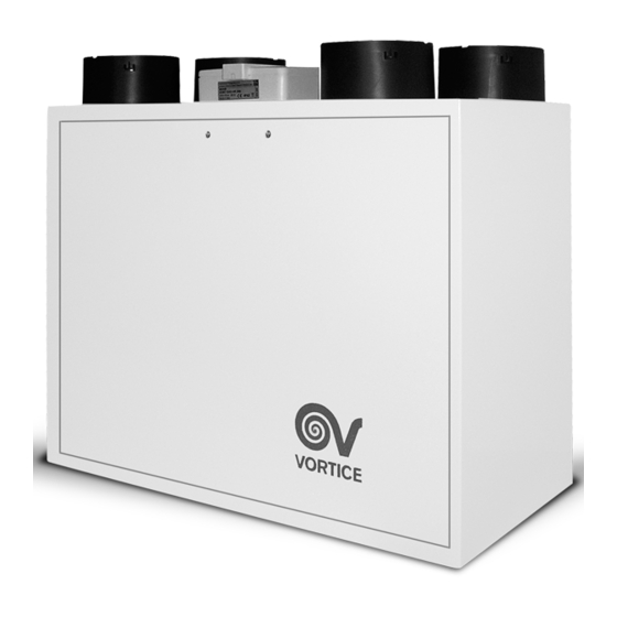
Seite 5: Struttura E Dotazione
ITALIANO Struttura e Dotazione Nel corso del normale funzionamento, sul fondo Le principali parti componenti l’apparecchio sono così dell’apparecchio si raccoglie condensa per il cui riassumibili: smaltimento è necessario applicare, in corrispondenza • involucro esterno e coperchio frontale, in lamiera dell’apposito attacco (fig. -
Seite 6: Installazione
ITALIANO Montaggio L’apparecchio è equipaggiato con 2 tasselli con gancio per il montaggio verticale a parete. Determinare l’esatta posizione destinazione dell’apparecchio, tenendo presenti i requisiti per l’installazione. Montaggio in verticale Fissare a muro i ganci, seguendo le figure successive. (fig. 4,5,6,7,8). - Seite 7 ITALIANO Montaggio in orizzontale (kit opzionale) Aspirazione aria fresca dall’esterno L’apparecchio può essere montato in orizzontale tramite (fig. 11) apposito kit opzionale. Connessione delle tubazioni (fig. 9). MANDATA ASPIRAZIONE ASPIRAZIONE MANDATA ARIA VIZIATA ARIA FRESCA ARIA VIZIATA ARIA FRESCA VERSO DALL’...
- Seite 8 ITALIANO Mandata aria fresca in casa (fig. 13) Questa bocca è utilizzata per immettere all’interno della casa l’aria fresca esterna, preventivamente trattata nello scambiatore di calore. Connessione del tubo di scarico condensa. punto connessione è posto fondo dell’apparecchio; esso deve essere predisposto secondo sequenza sotto descritta.(fig.
- Seite 9 ITALIANO Lo scarico della condensa deve essere realizzato connettendo il tubo flessibile in dotazione al raccordo scarico condensa. Per impedire la formazione di bolle d’aria occorre realizzare con il tubetto un sifone, come indicato in fig. 21...
- Seite 10 ITALIANO Montaggio scatola controllo remoto cablato: MERCATO ITA Montaggio scatola controllo remoto cablato: MERCATO NO ITA NO UK...
-
Seite 11: Schemi Di Collegamento
ITALIANO Schemi di collegamento GNYE MAINS MAINS 230V ~ 50Hz PREH PREH 230V ~50Hz Preheater (remote 230Vac relay coil ) Mains 2 poles switch BOOST BOOST Dry contact (remote switch / relay ) Remote HMI... - Seite 12 ITALIANO Funzionamento Motori L’apparecchio è equipaggiato di due motori brushless studiati per garantire bassissimi consumi, grazie alla loro elevata efficienza, azionanti due ventole centrifughe che estraggono l’aria viziata ed umida dai locali di servizio (cucine, bagni, lavanderie, ecc.) ed immettono aria fresca esterna nei locali abitativi (soggiorni, sale da pranzo, camere da letto, ecc.);...
-
Seite 13: Funzionamento
ITALIANO FUNZIONI PANNELLO COMANDI All’accensione il display visualizza il logo Vortice e dopo 10 secondi la velocità di funzionamento impostata prima dell’ultimo spegnimento. N.B. In generale, in mancanza di input utente, dopo due minuti il display torna alla schermata del logo, senza... - Seite 14 ITALIANO Tutte le altre funzioni sono raggiungibili a partire da un menu principale. Il menu principale si può visualizzare premendo nella schermata iniziale. MAIN MENU USE MENU ALARM SETUP 13 / 01 / 18 08:07 INFO M e n u principale Use menu Con questa opzione e tramite l’immissione di password nella schermata successiva si può...
- Seite 15 ITALIANO SET UP BYPASS E’ la temperatura di setpoint per il bypass. Il valore di default, modificabile, è 18°C. INSTALL SETP BYP SETUP BYP RESET FIL MBUS ID RESET FIL E’ la variabile per il reset del contatore filtri sporchi. Il valore di default è NO. Può essere impostato a SI nel caso di sostituzione dei filtri (o comunque quando si desidera) RESET FIL INSTALL...
- Seite 16 ITALIANO SPEED E’ la variabile che definisce la velocità impostata per i motori di Supply (IN) e di exhaust (OUT), con i valori 1,2,BOOST. I valori di default, modificabili in percentuale, sono: V1 I V BOOST I 100% V1 O V BOOST O 100% V2 I...
- Seite 17 ITALIANO Funzioni utente (password 013) Il menu utente presenta la seguente opzione: (per la quale è possibile selezionare “SI/NO”). ACTIVE PR - Attivazione programmazione settimanale: programmazione memorizzata (vedi “SETUP”) viene attivata...
- Seite 18 ITALIANO Alarm Con questa opzione è possibile gestire tutte le possibili voci di allarme. In caso di più errori questi dovranno essere gestiti uno per uno, a partire dal primo verificatosi. In queste situazioni viene emessa una segnalazione intermittente “Alarm!” sulla schermata iniziale, oppure i messaggi intermittenti “Alarm!”, “Block!” , “OFF” nel caso degli errori bloccanti (No Frost).
- Seite 19 ITALIANO Sonda T ext Un guasto del sensore della temperatura esterna genera questa segnalazione. Dopo aver risolto il problema (tramite intervento dell’Assistenza Tecnica) è possibile resettare l’errore (risposta “YES” su “CALL SERVICE”). ALARM MAIN MENU EXT PROBE USE MENU CALL ALARM SERVICE SETUP N.B.
- Seite 20 ITALIANO No Frost La procedura di anti congelamento viene eseguita automaticamente dall’apparecchio quando necessaria. In caso di procedura non riuscita (Preheater con temperature troppo basse) viene generata una segnalazione bloccante. Il sistema rimane inattivo per un’ora, dopo di che l’apparecchio resetta automaticamente l’errore, si riattiva e ripete il ciclo dall’inizio.
- Seite 21 ITALIANO PROGRAM Con questa opzione è possibile accedere all’impostazione della velocità di funzionamento, su sei fasce orarie (con ora di inizio e ora di fine), per ogni giorno della settimana e per due intervalli predefiniti: lunedi-venerdi e sabato- domenica. Procedere come indicato nel seguito, per tutti i giorni desiderati e per tutte le fasce desiderate: PROGRAM SETUP MONDAY...
- Seite 22 ITALIANO rimuovendo il pannello frontale ed estraendo i componenti in questione dalle sedi. La sostituzione del filtro standard G3 alloggiato nel canale di immissione dell’aria fresca con un filtro opzionale F5, assicura superiori capacità filtranti. Protezione antigelo Con l’approssimarsi delle condizioni ambientali che potrebbero favorire la fomazione di brina sulle pareti dello scambiatore, la scheda elettronica provvede automaticamente all’adeguamento della velocità...
-
Seite 23: Manutenzione/Pulizia
ITALIANO righe display); 3: uscire senza salvare e tornare alla pagina precedente 4: aumentare la velocità (OFF, 1, 2, Boost), o spostare il cursore sulla riga soprastante, o incrementare il valore; 5: diminuire la velocità o spostare il cursore sulla riga sottostante, o decrementare il valore;... - Seite 24 ITALIANO dell’impianto, con: - aumento delle perdite di carico nel circuito aria e (vedi anche paragrafo “Utilizzo”): riduzione di portata aria; - conseguente diminuzione della resa della macchina e peggioramento del confort in ambiente. Per accedere ai filtri eseguire le istruzioni seguenti: •...
- Seite 25 ENGLISH In caso di prolungato arresto dell’apparecchio si Pulizia esterna Per pulire le parti esterne dell’apparecchio rispettare le consiglia di rimuovere i filtri per prevenire i rischi di un istruzioni seguenti: loro danneggiamento indotto dalla possibile formazione • disconnettere l’apparecchio dalla rete elettrica; di condensa.
-
Seite 26: Description And Operation
Vortice expert shall be considered The incoming and outgoing air flow are perfectly improper. In this case, Vortice shall not be held separate and suitably filtered. During the cold season, responsible for any malfunction or failure. -
Seite 27: Safety
Vortice spares are used for any repairs. • Should the appliance be dropped or suffer a heavy blow, have it checked immediately by a Vortice Service Centre. • The appliance must be installed by a professionally qualified electrician. -
Seite 28: Items Supplied
ENGLISH Items supplied attached to the coupling on the underside of the appliance and connected to a drainage hose (see The main appliance components are as follows: Assembly). • an outer casing and front cover in painted sheet metal; the casing houses the intake/outlet hose connections and the electrical connection box;... - Seite 29 ENGLISH Assembly The appliance comes with 2 rawlplugs with hooks for wall-mounting. Establish exactly where the appliance is to be positioned, bearing in mind the installation requirements. Vertical mounting Fix the hooks to the wall as shown in the diagrams that follow (figs.
- Seite 30 ENGLISH Floor mounting (optional kit) Fresh air inlet The appliance can be horizontally floor mounted using (fig. 11) the special optional kit. Pipework connections (fig. 9). EXTRACT SUPPLY EXTRACT SUPPLY FROM FROM EXTERNAL EXTERNAL INTERNAL INTERNAL This inlet is used for carrying fresh air from the exterior; the duct must be thermally insulated and have devices fitted to absorb vibration.
- Seite 31 ENGLISH Air outlet (fig. 13) This outlet delivers fresh air into the house once it has been treated in the heat exchanger. Connecting the condensation drainage hose. The connection point for this hose is located on the underside of the appliance; it is to be connected following the description below (figs.14,15,16, 17,18,19,20).
- Seite 32 ENGLISH Condensation is drained away by connecting the hose provided to the condensation drainage coupling. To prevent formation of air locks a U-bend must be created with the hose as shown in fig. 21.
- Seite 33 ENGLISH Mounting the wired remote control ITA MARKET Mounting the wired remote control NO ITA NO UK MARKET...
-
Seite 34: Electrical Connections
ENGLISH Electrical connections GNYE MAINS MAINS 230V ~ 50Hz PREH PREH 230V ~50Hz Preheater (remote 230Vac relay coil ) Mains 2 poles switch BOOST BOOST Dry contact (remote switch / relay ) Remote HMI... -
Seite 35: Function
ENGLISH Function Motors INFORMATIONS The appliance is equipped with: All functions can be controlled via the wired control panel • two brushless motors specifically designed to equipped with touch screen: guarantee very low energy consumption thanks to their high efficiency. These motors drive two centrifugal fans which extract the stale damp air from service rooms (kitchens, bathrooms, washrooms, etc) and introduce fresh external air into living areas (sitting rooms, dining... - Seite 36 ENGLISH CONTROL PANEL FUNCTIONS Upon start-up, the display shows the Vortice logo for about 10 sec and then the set operating speed before the last shut-down. NOTE: in general, in the absence of user input, after two minutes the display will return to the logo screen without...
- Seite 37 ENGLISH All other functions can be reached from the main menu.The main menu can be displayed by pressing on the home screen. MAIN MENU USE MENU ALARM SETUP 13 / 01 / 18 08:07 INFO Main menu Use menu With this option and by entering the password on the next screen, you can access installer and user settings. Installer settings: password: 023 User settings: password: 13 MAIN MENU...
- Seite 38 ENGLISH SET UP BYPASS This is the setpoint temperature for bypass. The editable default value is 18°C. SETP BYP INSTALL SETUP BYP RESET FIL MBUS ID RESET FIL This is the variable for dirty filter counter reset. The default value is NO. It can be set to YES in the case of filter replacement (or however when desired) RESET FIL INSTALL...
- Seite 39 ENGLISH SPEED This is the variable that defines the speed set for Supply (IN) and exhaust (OUT) motors, with the values 1,2,BOOST and BOOST. The default values, which are editable as a percentage, are: V BOOST I 100% V1_I V1_O V BOOST O 100% V2_I...
- Seite 40 ENGLISH User functions (password 013) The user menu offers the following options: (you can select "YES/NO" for each). ACTIVE PR - Weekly programming activation: saved programming (see "SETUP") is activated.
- Seite 41 ENGLISH Alarm This option allows you to manage all possible alarm messages. Multiple errors must be managed one by one, starting from the first one that occurred. In these situations, an intermittent "Alarm!" signal will be emitted on the home screen. The intermittent messages "Alarm!", "Block!" and “OFF” will be displayed only in the event of a "No Frost"...
- Seite 42 ENGLISH T ext probe A fault on the external temperature sensor generates this signal. After having resolved the problem (through Technical Service intervention), you can reset the error (answer "YES" for "CALL SERVICE"). ALARM MAIN MENU EXT PROBE USE MENU CALL ALARM SERVICE SETUP Note: The system does not automatically call Technical Service.
- Seite 43 ENGLISH No Frost The frost protection procedure is carried out automatically by the device when necessary. A blocking signal will be generated if the procedure does not work (pre-heater with temperature too low). The system will remain inactive for an hour; after which, the device will automatically reset the error, and the cycle will reactivate and repeat from the beginning.
- Seite 44 ENGLISH PROGRAM With this option, you can access operating speed setting for six time slots (with start and end times) for each day of the week and for two pre-set intervals: Monday-Friday and Saturday-Sunday. Proceed as follows for all desired days and time slots: PROGRAM SETUP DATE&HOUR...
-
Seite 45: Maintenance/Cleaning
ENGLISH Maintenance/Cleaning Filters Recommended maintenance intervals: because levels of air pollution depend typically on geographical location and are variable, the life of the filters will be similarly variable. With this general consideration in mind, check following alarms for filter maintenance (see also “Use”): - Pre-alarm: actives the notice about filters checking and cleaning - Alarm: actives the notice about clogged filters... - Seite 46 ENGLISH If the appliance remains out of use for extended periods, we advise removing the filters to prevent any possible damage from the build-up of condensation. Heat exchanger Heat exchangers do not usually need frequent cleaning. Any need for cleaning can be determined by a high degree of air pollution (both entering and leaving the house) and by the filters being in poor condition.
- Seite 47 ENGLISH • do not use abrasive and/or corrosive products (fig. 38); • do not use a rough and/or soaking cloth; any water that gets inside the appliance could cause serious damage. Cleaning the outside To clean the outside of the appliance, follow the instructions below: •...
-
Seite 48: Description Et Mode D'employ
équilibrés ». Toute autre utilisation, si elle n’a pas reçu sont à peu près équivalents. Les flux d’air entrant et l’approbation préalable d’un expert Vortice, peut être sortant sont parfaitement séparés et filtrés. Pendant la considérée comme impropre. Dans ce cas, Vortice saison froide, la chaleur de l’air expulsé... -
Seite 49: Sécurité
Service après-vente agréé Vortice. • En cas de disfonctionnement et/ou de panne, s’adresser immédiatement à un Service après-vente agréé Vortice et exiger, en cas de réparation, l’emploi de pièces détachées d’origine. • Si l’appareil tombe ou reçoit des coups violents, le faire vérifier immédiatement par un Service après-vente... -
Seite 50: Structure De L'appareil Et Accessoires
FRANCAIS Structure de l’appareil et accessoires Pendant le fonctionnement, la condensation s’accumule en bas de l’appareil. Pour l’évacuer, appliquer au raccord Les principales pièces qui composent l’appareil sont les correspondant (fig. 2) le tuyau de série qui acheminera suivantes. l’eau vers l’évacuation (voir chapitre « Montage »). •... - Seite 51 FRANCAIS Montage L’appareil est muni de deux chevilles à crochets pour le montage vertical sur une cloison. Déterminer l’emplacement exact de l’appareil compte tenu des paramètres à respecter pour l’installation. Montage en position verticale Fixer les crochets au mur d’après les figures suivantes (fig.
- Seite 52 FRANCAIS Montage en position horizontale (kit en option) Aspiration d’air frais de l’extérieur L’appareil peut être monté en position horizontale avec le (fig. 11) kit spécial en option. Raccordement des conduites (fig. 9) REFOULEMENT ASPIRATION ASPIRATION REFOULEMENT AIR IMPUR AIR FRAIS AIR IMPUR AIR PUR VERS...
- Seite 53 FRANCAIS Refoulement d’air frais dans l’habitation (fig. 13) Cette bouche permet l’apport dans l’habitation d’air frais arrivant de l’extérieur traité par l’échangeur de chaleur. Raccordement tuyau d’évacuation condensation Le point de raccordement est situé en bas l’appareil. Il doit être préparé conformément à la procédure décrite par les figures suivantes (fig.
- Seite 54 FRANCAIS Réaliser l’évacuation de la condensation en branchant le tuyau flexible de série au raccord spécial. Pour éviter les bulles d’air, former un siphon avec le tuyau comme le montre la fig. 21.
- Seite 55 FRANCAIS Montage boîtier commande à distance câblé MARCHE’ ITA Montage boîtier commande à distance câblé MARCHE’ NON ITA NON UK...
-
Seite 56: Branchements Électriques
FRANCAIS Branchements électriques GNYE MAINS MAINS 230V ~ 50Hz PREH PREH 230V ~50Hz Preheater (remote 230Vac relay coil ) Mains 2 poles switch BOOST BOOST Dry contact (remote switch / relay ) Remote HMI... -
Seite 57: Fonctionnement
FRANCAIS Fonctionnement Utilisation Moteurs GENERALITES L’appareil est équipé de : Toutes les fonctions de l'appareil peuvent être contrôlées • deux moteurs à courant continu haute performance qui au moyen d'un clavier de commande câblé, doté d'écran ont été spécialement étudiés pour leur très faible tactile: consommation d’énergie. - Seite 58 FRANCAIS FONCTIONS CLAVIER DE COMMANDES Au démarrage, l'écran affiche le logo Vortice et après 10 s la vitesse de fonctionnement programmée avant le dernier arrêt de l'appareil. En général, sans aucune action de la part de l'utilisateur, l'écran retourne à la page du logo après deux minutes,...
- Seite 59 FRANCAIS Toutes les autres fonctions peuvent être activées sur le menu principal. Le menu principal peut être affiché en appuyant sur la page d'accueil. MAIN MENU USE MENU ALARM SETUP 13 / 01 / 18 08:07 INFO Menu principal Use nenu Avec cette option, et au moyen de la saisie d'un mot de passe sur la page d'écran successive, on peut accéder aux programmations de compétence de l'installateur et de l'utilisateur : Installateur : mot de passe : 023 Utilisateur : mot de passe 013...
- Seite 60 FRANCAIS SET UP BYPASS C'est la température de consigne pour le bypass. La valeur par défaut modifiable est 18°C INSTALL SETP BYP SETUP BYP RESET FIL MBUS ID RESET FIL C'est la variable pour la remise à zéro du compteur filtres sales. La valeur par défaut est NON. Elle peut être pro- grammée sur OUI en cas de remplacement de filtres (ou quand vous le souhaitez).
- Seite 61 FRANCAIS SPEED C'est la variable qui définit la vitesse programmée pour les moteurs Supply (IN) et Exhaust (OUT). Il y a 3 vitesses (plus OFF). Les valeurs par défaut, modifiables en pourcentage, sont : V1_I V BOOST I 100% V1_O V BOOST O 100% V2_I...
- Seite 62 FRANCAIS Fonctions utilisateur (mot de passe 013) Le menu utilisateur présente les options suivantes: (il est possible de sélectionner “OUI/NON” pour toutes les options). ACTIVE PR - Activation programmation hebdomadaire programmation mémorisée (voir “SETUP”) est activée...
- Seite 63 FRANCAIS Alarm Avec cette option, il est possible de gérer toutes les rubriques d'alarme possibles. En cas de plusieurs erreurs, celles-ci devront être gérées l'une après l'autre, en commençant par la première qui est apparue. Dans ce genre de situations, une signalisation intermittente “Alarm!” est émise sur la page d'accueil, ou les messages intermittents “Alarm!”, “Block!”, “OFF”...
- Seite 64 FRANCAIS Sonde T ext Une panne du capteur de température extérieure génère cette erreur. Après avoir résolu le problème (au moyen de l'intervention de l’assistance technique) il est possible de réinitialiser l'erreur (réponse “YES” sur “CALL SERVICE”). ALARM MAIN MENU EXT PROBE USE MENU CALL ALARM...
- Seite 65 FRANCAIS No Frost La procédure d'antigel est réalisée automatiquement par l'appareil quand nécessaire. En cas de procédure ratée (Préchauffeur avec des températures trop basses), un signal de verrouillage est généré. Le système reste désactivé pendant une heure puis l'appareil réinitialise automatiquement l'erreur, il se réactive et répète le cycle depuis le début.
- Seite 66 FRANCAIS PROGRAM Avec cette option, il est possible d'accéder à la programmation de la vitesse de fonctionnement, sur six plages horaires (avec heure de début et heure de fin), pour chaque jour de la semaine et pour deux intervalles prédéfinis : lundi-vendredi et samedi-dimanche.
-
Seite 67: Entretien Et Nettoyage
FRANCAIS Entretien et nettoyage Filtres Délais conseillés pour l'entretien: en général, le niveau de pollution de l'air varie en fonction de la zone géographique d'installation; la durée des filtres est donc elle aussi variable; on conseille toutefois de les remplacer une fois par an. En tenant compte de ces considérations, les alarmes pour l'entretien des filtres sont les suivantes: •... - Seite 68 FRANCAIS En cas d’arrêt prolongé de l’appareil, il est conseillé d’enlever les filtres pour les protéger contre les effets de la condensation. Échangeur de chaleur En temps normal, l’échangeur de chaleur ne nécessite pas de nettoyages fréquents. On peut être amené à le nettoyer plus souvent si l’air entrant ou sortant est très pollué...
- Seite 69 FRANCAIS • Ne pas utiliser de produits abrasifs ou corrosifs (fig. 38). • Ne pas utiliser de chiffon rugueux ou trop mouillé : en pénétrant dans l’appareil, l’eau pourrait gravement l’endommager. Nettoyage extérieur Pour nettoyer les pièces extérieures de l’appareil, suivre les instructions ci-dessous.
-
Seite 70: Beschreibung Und Gebrauch
Ab- und Zuluft im Wesentlichen die Waage. Zu- und gilt als unsachgemäß und zweckfremd. In einem solchen Abluftstrom sind vollkommen getrennt und werden Fall haftet Vortice nicht für allfällige Betriebsstörungen, entsprechend gefiltert. In der kalten Jahreszeit wird die Defekte und/oder Probleme. -
Seite 71: Sicherheit
DEUTSCH Sicherheit • Fällt das Gerät um oder wurde es starken Stößen ausgesetzt, muss es ehestmöglich von einem Vortice- Vertragshändler überprüft werden. Achtung: • Die Installation Gerätes darf durch dieses Symbol zeigt Vorsichtsmaßnahmen qualifiziertes Fachpersonal erfolgen. zum Schutz des Benutzers an •... -
Seite 72: Aufbau Und Ausstattung
DEUTSCH Aufbau und Ausstattung Nenndurchmesser von 125 mm haben und mit Schellen oder anderen geeigneten Dichtsystemen an den Auflistung und Beschreibung der Hauptkomponenten entsprechenden Stutzen des Gerätes befestigt werden. des Gerätes: • Das Gehäuse und die vordere Abdeckung sind aus Während des normalen Betriebs sammelt sich am lackiertem Blech. - Seite 73 DEUTSCH Montage Das Gerät wird mit 2 Dübeln mit Haken für die senkrechte Montage an der Wand geliefert. Bei der genauen Festlegung des Installationsortes die Voraussetzungen für eine korrekte Montage beachten. Senkrechte Montage an einer Wand Die Haken wie auf den folgenden Abbildungen gezeigt an der Wand befestigen (Abb.
- Seite 74 DEUTSCH Waagrechte Montage (als Sonderausstattung Ansaugung von Frischluft erhältliches Montageset) (Abb. 11) Das Gerät kann mit Hilfe eines als Sonderausstattung erhältlichen Montagesets in waagrechter Stellung installiert werden. Anschluss der Leitungen (Abb. 9). REFOULEMENT ASPIRATION ASPIRATION REFOULEMENT AIR IMPUR AIR FRAIS AIR IMPUR AIR PUR VERS...
- Seite 75 DEUTSCH Zuleitung von Frischluft in das Haus/die Wohnung (Abb. 13) Dieser Stutzen dient Zuführung Wärmeaustauscher aufbereiteter Frischluft in das Haus/die Wohnung. Anschluss für die Kondenswasserableitung Die Anschlussstelle befindet sich im Geräteboden; der Anschluss muss in der unten angegebenen Reihenfolge ausgeführt werden (Abbildungen 14,15,16,17,18,19,20).
- Seite 76 DEUTSCH Die Kondenswasserableitung muss durch Anschließen mitgelieferten Schlauchs Kondenswasserableitungsanschluss erfolgen. Um die Bildung von Luftblasen zu verhindern, muss mit der Leitung ein Sifon gebildet werden - siehe Abbildung 21.
- Seite 77 DEUTSCH Montage des Kastens mit der verkabelten Fernsteuerung ITA MARKT Montage des Kastens mit der verkabelten Fernsteuerung NICHT ITA MARKT, NICHT UK MARKT...
-
Seite 78: Stromanschlüsse
DEUTSCH Stromanschlüsse GNYE MAINS MAINS 230V ~ 50Hz PREH PREH 230V ~50Hz Preheater (remote 230Vac relay coil ) Mains 2 poles switch BOOST BOOST Dry contact (remote switch / relay ) Remote HMI... -
Seite 79: Funktionbeschreibung
DEUTSCH Funktionsbeschreibung Gebrauch Motoren ALLGEMEINES Zum Gerät gehören die folgenden Komponenten: Alle Gerätefunktionen sind über ein verkabeltes • Zwei bürstenlose Motoren, die dank ihrer hohen Bedienfeld mit Touchscreen steuerbar: Effizienz einen extrem niedrigen Verbrauch haben und zwei Zentrifugallüfter antreiben, welche verbrauchte und feuchte Luft aus den bedienten Räumen (Küchen, Badezimmern, Waschraum usw.) abziehen und Frischluft von außen in die Wohnräume... - Seite 80 DEUTSCH FUNKTIONEN DER BEDIENFELDER Bei Einschaltung zeigt das Display das Logo von Vortice und nach 10 s die Betriebsgeschwindigkeit an, die vor der letzten Ausschaltung eingestellt war. HINWEIS: In der Regel schaltet das Display nach zwei Minuten ohne Eingaben durch den Benutzer zurück zur...
- Seite 81 DEUTSCH Alle anderen Funktionen sind über das Hauptmenü zugänglich. Das Hauptmenü kann man anzeigen, indem man auf der Startseite drückt. MAIN MENU USE MENU ALARM SETUP 13 / 01 / 18 08:07 INFO Hauptmenü Use menu Nach Eingabe des Passworts auf der nächsten Seite hat man mit dieser Option Zugang zu den Einstellungen für Installateur und Benutzer: Installateur: Passwort: 023 Benutzer: Passwort 013...
-
Seite 82: Bypass-Einstellung
DEUTSCH BYPASS-EINSTELLUNG Es handelt sich um die Sollwerttemperatur für den Bypass. Die änderbare Standardeinstellung ist 18°C INSTALL SETP BYP SETUP BYP RESET FIL MBUS ID FIL RÜCK Es ist die Variable für die Rückstellung des Zählers der verschmutzten Filter. Die Standardein- stellung ist NEIN. - Seite 83 DEUTSCH SPEED Es ist die Variable mit der eingestellten Geschwindigkeit für die Motoren Supply (IN) und Exhaust (OUT). Möglich sind 3 Geschwindigkeiten (plus OFF). Die in Prozent änderbaren Standardeinstellungen sind: V1_I V BOOST I 100% V1_O V BOOST O 100% V2_I V2_O INSTALL...
- Seite 84 DEUTSCH Benutzerfunktionen (Passwort 013) Im Benutzermenü gibt es folgende Optionen: (Für alle Möglichkeiten “JA/NEIN” eingeben). ACTIVE PR Aktivierung Wochenprogramm: das gespeicherte Programm (siehe “SETUP”) wird aktiviert.
- Seite 85 DEUTSCH Alarm Mit dieser Option können alle möglichen Alarmpunkte gesteuert werden. Bei mehrere Fehlern, müssen diese ab dem zuerst aufgetretenen einzelnen, nacheinander gesteuert werden. In dieser Situation kommt es zum Blinksignal “Alarm!” auf der Startseite oder zu den blinken Meldungen “Alarm!”, “Block!” , “OFF” bei Fehler, die das Gerät blockieren.
- Seite 86 DEUTSCH Sonde T ext Ein defekter Sensor der Außentemperatur generiert diesen Fehler ohne Geräteblockierung (nur die Wärmepumpe wird blockiert). Nach der Problemlösung (durch den Kundenservice) kann der Fehler resettet werden (Antwort “YES” bei “CALL SERVICE”). ALARM MAIN MENU EXT PROBE USE MENU CALL ALARM SERVICE SETUP...
- Seite 87 DEUTSCH No Frost Das Verfahren zum Frostschutz wird bei Bedarf vom Gerät automatisch ausgeführt. Im Fall eines missglückten Ver- fahrens (Vorheizgerät mit zu niedrigen Temperaturen) wird ein blockierendes Signal ausgegeben. Das System bleibt für eine Stunde deaktiviert, danach setzt das Gerät den Fehler automatisch zurück, startet neu und führt den Zyklus wieder von Anfang an durch.
- Seite 88 DEUTSCH PROGRAM Mit dieser Option gelangt man zur Einstellung der Betriebsgeschwindigkeit in sechs Zeitspannen (mit Uhrzeit von Beginn und Ende), pro Wochentag und zwei voreingestellte Zeiträume: Montag-Freitag und Samstag-Sonntag. Wie nachstehend beschrieben mit der Einstellung für alle gewünschten Tage und Zeitspannen fortfahren. PROGRAM SETUP DATE&HOUR...
-
Seite 89: Wartung Und Reinigung
DEUTSCH Wartung und Reinigung Filter Empfohlene Wartungsintervalle: Die Lebensdauer der Filter hängt Luftverschmutzung geografischen Gebiets ab, in dem sie installiert sind, d.h. sie kann von Ort zu Ort variieren; wir empfehlen, sie einmal pro Jahr auszuwechseln. Wenn man dies berücksichtigt, ergeben sich folgende Alarme für die Wartung der Filter: •... - Seite 90 DEUTSCH Vor einer längeren Nichtbenutzung des Gerätes sollten die Filter ausgebaut werden, um eine mögliche Beschädigung durch Kondenswasserbildung verhindern. Wärmeaustauscher In der Regel muss der Wärmeaustauscher nicht allzu oft gereinigt werden. Wie oft dies erforderlich ist, hängt vom Verschmutzungsgrad der Zu- und Abluft und der Effizienz der Filter ab.
- Seite 91 DEUTSCH • Keine Scheuermittel und/oder korrosiven Produkte verwenden (Abb. 38). • Keine rauhen und/oder zu feuchten Tücher benutzen, da die Feuchtigkeit in das Geräteinnere eindringen und dort schwere Schäden verursachen könnte. Reinigung des Gehäuses Zum Reinigen des Geräteäußeren wie folgt vorgehen: •...
- Seite 92 Vortice Elettrosociali S.p.A. reserves the right to make improvements to products at any time and without prior notice. La société Vortice Elettrosociali S.p.A. se réserve le droit d'apporter toutes les variations afin d'améliorer ses produits en cours de commercialisation. Die Firma Vortice Elettrosociali S.p.A. behält sich vor, alle eventuellen Verbesserungsänderungen an den Produkten des Verkaufsangebots vorzunehmen.
- Seite 94 TAGLIANDO INTERVENTO IN GARANZIA CERTIFICATE OF WORK PERFORMED UNDER GUARANTEE COUPON INTERVENTION SOUS GARANTIE DATA INTERVENTO TIMBRO CENTRO ASSISTENZA DATE OF WORK - DATE INTERVENTION STAMP OF TECHNICAL ASSISTANCE CENTRE - CACHET SERVICE APRES-VE TAGLIANDO INTERVENTO IN GARANZIA CERTIFICATE OF WORK PERFORMED UNDER GUARANTEE COUPON INTERVENTION SOUS GARANTIE DATA INTERVENTO TIMBRO CENTRO ASSISTENZA...
- Seite 95 Company will consider written applications for transfer. Should Assistenza Tecnica autorizzati da VORTICE ELETTROSOCIALI SPA, any defect arise in any Vortice product and a claim under guarantee il cui indirizzo è disponibile sull’elenco telefonico alfabetico o become necessary, the appliance should be carefully packed and contattando il numero verde 800.555.777.
- Seite 96 GARANZIA - GUARANTEE - GARANTIE Per poter usufruire della garanzia il cliente deve compilare e rispedire a VORTICE ELETTROSOCIALI SPA, entro 8 giorni dall’acquisto, la “Parte 2” del tagliando di garanzia, all’indirizzo e con le modalità in tale parte riportate.