SAFETY INSTRUCTIONS SAVE THESE INSTRUCTIONS. This manual contains important instructions that should be followed during installation and maintenance of the UPS and batteries. UPS Tower models are considered acceptable for use in the ambient of 0 ~ 45°C; UPS RT models are considered acceptable for use in the ambient of 0 ~ 40°C; Certification standards Safety: IEC/EN 62040-1 •...
Seite 3
knowledgeable about batteries and the required precautions. - Risk of explosion if battery is replaced by an incorrect type. When replacing batteries, replace with the same type and number of batteries or battery packs. Instructions shall carry sufficient information to enable the replacement of the battery with a suitable recommended type.
Seite 4
and to the actual electrical consumption of all the equipment to be connected to the system. Never install the system near liquids or in an excessively damp environment. Never let a foreign body penetrate inside the system. Never block the ventilation grates of the system. ...
1 Introduction Thank you for selecting PowerWalker VFI ICT/ICR IoT UPS to protect your electrical equipment. We recommend that you take the time to read this manual to take full advantage of the many features of the UPS (Uninterruptible Power System).
1.2 Environmental protection Products are developed according to an eco-design approach. Substances This product does not contain CFCs, HCFCs or asbestos. Packing To improve waste treatment and facilitate recycling, separate the various packing components. The cardboard we use comprises over 50% of recycled cardboard. •...
2 Product Overview 2.1 Weight and Dimension The weights in this table is reference only, please see the labels on the carton for details. Tower models: Description Net Weights (kg) Dimensions: D x W x H (mm) Tower 1K 12.8 404 X 145 X 220 Tower 1KS 404 X 145 X 220...
Seite 9
RT models Description Net Weights (kg) Dimensions: D x W x H (mm) RT 1K 14.3 445*438*85.5 RT 1KS 445*438*85.5 RT 1.5K 15.8 445*438*85.5 RT 1.5KS 445*438*85.5 RT 2K 23.3 600*438*85.5 RT 2KS 10.6 600*438*85.5 RT 3K 26.2 600*438*85.5 RT 3KS 11.0 600*438*85.5 RT 36V EBM...
3 Installation 3.1 Inspecting the equipment If any equipment has been damaged during shipment, keep the shipping cartons and packing materials for the carrier or place of purchase and file a claim for shipping damage. If you discover damage after acceptance, file a claim for concealed damage. To file a claim for shipping damage or concealed damage: 1.
Seite 15
RT model Output cables Input cable USB cable User manual (English) Tower stands User manual (Multi-Language) (optional) RS232 cable (optional) Slot card (optional) Rail kit (optional) Cable lockers (optional)
3.3 Install the Unit Always keep 200 mm of free space behind the UPS rear panel. Check that the indications on the name plate located on the top cover of the UPS meets to the AC-power source and the true electrical consumption of the total load. 1.
Seite 17
Recommended upstream protection UPS model Upstream circuit breaker Tower 3KS C curve-20A Input terminal and output terminal connection: Terminal-block capacity Tower 3KS Minimum of section required/ Torque 4 mm² Input L, N, G · mm²/(0.3 N conductor cross section Output L, N, G 10 mm²...
Seite 18
3.3.1 RT models Rack installation Follow steps 1 to 4 for module mounting on the rails.
Tower installation 3.4 Connecting the EBM(s) A small amount of arcing may occur when connecting an EBM to the UPS. This is normal and will not harm personnel. Up to 4 EBMs can be connected to the UPS. 3.4.1 Tower models 1k/1.5k...
4 Operation 4.1 LCD panel The UPS provides useful information about the UPS itself, load status, events, measurements and settings. The following table shows the indicator status and description: Indicator Status Description The UPS is operating normally on Online or on High Efficiency mode.
The following table shows the indicator status and description: The button Function Illustration Press the Button for >100ms & < 1s can power on the UPS without utility input at the condition of Power on battery connected When the Unity is powered on, press the button Turn on for >1s can turn on the UPS Press the button >...
Seite 23
Operation status Cause Description Standby mode The UPS is Off without output. The UPS is operating normally and protecting the Online mode equipment. A utility failure has occurred, and the UPS is powering the equipment with battery. Battery mode 1 beep every 4 Prepare your equipment for shutdown.
4.3 Display functions When starting the UPS, the display is in the default UPS status summary screen. Main menu Submenu Display information or Menu function UPS mode, IoT status, date/time, battery status and UPS status current alarms Event log Displays the events and faults stored [Load] W VA A P%, [Input/Output] V Hz, Measurements [Battery] % min V EBM, [DC Bus] V, [Temperature] C...
4.6 Starting the UPS on Battery Before using this feature, the UPS must have been powered by utility power with output enabled at least once. Battery start can be disabled. Refer to the Chapter 4.4 User setting 4.7 UPS Shutdown...
5 Communication RS232 and USB 1. Communication cable to the serial or USB port on the computer. 2. Connect the other end of the communication cable to the RS232 or USB communication port on the UPS. 5.2 UPS remote control functions ...
Inner Relay specification 24Vdc/1A 5.3 IoT Built-in ethernet port and WLAN (optional accessary) port enable market-leading and easy-to-use IoT solutions for: o Winpower View mobile app which allows you to remote monitor UPS(s) and keep informed about critical UPS event always. o Remote report UPS faults and status (contact with your service for detail) from APP or registered APP account (Email address) o Automatic UPS and battery warranty alert from APP or registered APP account...
5.5 Intelligent Card (Optional) Intelligent Card allow the UPS to communicate with different types of devices in variety of networking environments. The PowerWalker VFI ICT/ICR IoT series could use the following connectivity cards, please contact your local distributor for details •...
LAN no matter how far from the UPSs. Installation procedure: 1. Go to the website: https://powerwalker.com/?page=winpower&lang=en 2. Choose the operation system you need and follow the instruction described on the website to download the software. 3. When downloading all required files from the internet, enter the serial No: 511C1- 01220-0100-478DF2A to install the software.
Seite 31
5.6.2 WinPower View APP WinPower View is a mobile app which allows you to centralized monitoring UPS(s) connected to cloud. Please download it from Google Play store or Apple APP store. Please refer to the chapter 5.3 for IoT connection.
6 UPS maintenance 6.1 Equipment care For the best preventive maintenance, keep the area around the equipment clean and dust free. If the atmosphere is very dusty, clean the outside of the system with a vacuum cleaner. For full battery life, keep the equipment at an ambient temperature of 25°C (77°F). The batteries are rated for a 3-5-year service life.
Seite 33
• Replacing the internal battery(For RT) Put the new battery pack into the UPS. Screw back the metal protection covers and the front panel. Testing new batteries. Verify that the replacement batteries have the same rating and brand as the batteries being replaced...
6.5 Recycle Contact your local recycling or hazardous waste center for information on proper disposal of the used equipment. Do not dispose of the batteries in the fire. Which may cause battery explosion. The batteries must be rightly disposed according to local regulation. Do not open or destroy the batteries.
7 Troubleshooting Typical alarms and faults: To check the UPS status and Event log: 1. Press any button on the front panel display to activate the menu options. 2. Press the button to select Event log. 3. Scroll through the listed events and faults. The following table describes typical conditions.
Seite 36
Conditions Possible cause Action Bypass mode An overload or a fault has Equipment is powered but not protected occurred, or a command has by the UPS. Check for one of the following been received and the UPS is alarms: overtemperature, overload, UPS LED is on.
8 Specifications 8.1 UPS Block Diagram 8.2 UPS Specification Model name 1.5K 1.5KS Power rating VA/Watt 1000VA/1000W 1500VA/1500W 2000VA/2000W 3000VA/3000W Line mode Efficiency ECO mode Voltage range 160-300V 100% load, 110-160V derating to 50% load linearly Rated frequency 50Hz/60Hz Input Frequency range 40Hz-70Hz (45Hz-55Hz, 54Hz-66Hz @ load>60%) performance...
Seite 38
Model name 1.5K 1.5KS 1 main outlet group (with 1 x IEC C19 + 4 x 1 main outlet group (with 4 x IEC C13) Socket (RT) IEC C13) 1 programmable outlet group (with 4 x IEC C13) 1 programmable outlet group (with 4 x IEC C13) Socket 8 x IEC C13...
Seite 39
Model name 1.5K 1.5KS Plug solid RT: Optional; Tower: NA Wheel Operating RT: 0-40⁰C Tower: 0-45⁰C, 40-45⁰C derating to 80% temperature Relative 0-95% Humidity Environment Operating 0~3000m(the load derating 1 % every up 100m @1000~3000m) Altitude Acoustic Noise <45dB at front 1m <50dB at front 1m Certification CE, IEC/EN 62040...
Seite 41
PowerWalker VFI ICT/ICR IoT Serie BENUTZERHANDBUCH Service und Unterstützung: Rufen Sie Ihren lokalen Servicevertreter an...
SICHERHEITSHINWEISE BEWAHREN SIE DIESE ANWEISUNGEN AUF. Dieses Handbuch enthält wichtige Anweisungen, die bei der Installation und Wartung der USV und der Batterien befolgt werden sollten. USV- Tower-Modelle gelten als geeignet für die Verwendung in einer Umgebung von 0 ~ 45°C; USV-RT-Modelle (Rack-Tower) gelten als geeignet für die Verwendung in einer Umgebung von 0 ~ 40°C;...
Seite 43
• Die mit dem System gelieferte Batterie enthält geringe Mengen toxischer Stoffe. Um Unfälle zu vermeiden, sind die unten aufgeführten Richtlinien zu beachten: Die Wartung von Batterien sollte von Personal durchgeführt oder beaufsichtigt werden, das über Batterien und den erforderlichen Vorsichtsmaßnahmen Kenntnisse hat.
Seite 44
• Für das 3kVA KS Modell ist ein Leistungsschutzschalter mit Nennwert 20A, Auslösekurve C erforderlich. • Der vorgeschaltete Schutzschalter für Normal AC / Bypass AC muss leicht zugänglich sein. • für PERMANENT ANGESCHLOSSENE GERÄTE muss eine leicht zugängliche Trennvorrichtung außerhalb des Gerätes eingebaut sein •...
Seite 45
Inhalt Schutz der elektronischen Ausrüstung ..........1 Umweltschutz .................... 2 2 Produkt-Übersicht ...................... 3 Gewicht und Abmessungen ..............3 Rückseiten ....................5 Installation ....................... 9 Inspektion der Inhalts ................9 Prüfung des Zubehörsatzes ..............9 Einbau der Einheit ................11 Verbindung der EBM(s) (externes Batteriemodul) ....
Seite 46
USV-Schaltdiagramm ................33 USV-Spezifikation .................. 33...
1 Einleitung Vielen Dank, dass Sie sich für eine PowerWalker VFI ICT/ICR IoT UPS zum Schutz Ihrer elektrischen Ausrüstungen entschieden haben. Wir empfehlen Ihnen, sich die Zeit zu nehmen, dieses Handbuch zu lesen, um die vielen Funktionen der USV (Unterbrechungsfreies Stromversorgungssystem) komplett nutzen zu können.
Umweltschutz Produkte werden nach einem Ökodesign-Ansatz entwickelt. Stoffe Dieses Produkt enthält weder FCKW, H-FCKW noch Asbest. Verpackung Um die Abfallverwertung zu verbessern und das Recycling zu erleichtern, trennen Sie die verschiedenen Verpackungskomponenten. • Der von uns verwendete Karton besteht zu über 50 % aus recyceltem Karton. •...
2 Produkt-Übersicht Gewicht und Abmessungen Die Gewichte in dieser Tabelle dienen nur als Referenz. Einzelheiten entnehmen Sie bitte den Etiketten auf dem Karton. Tower Modelle: Beschreibung Nettogewichte (kg) Abmessungen: T x B x H (mm) Tower 1K 12,8 404 x 145 x 220 Tower 1KS 404 x 145 x 220 Tower 1,5K...
Seite 50
RT-Modelle (Rack-Tower) Beschreibung Nettogewichte (kg) Abmessungen: T x B x H (mm) RT 1K 14,3 445 x 438 x 85,5 RT 1KS 445 x 438 x 85,5 RT 1,5K 15,8 445 x 438 x 85,5 RT 1,5KS 445 x 438 x 85,5 RT 2K 23,3 600 x 438 x 85,5...
3 Installation Inspektion der Inhalts Wenn irgendein Teil des Inhalts während des Transports beschädigt wurde, bewahren Sie die Versandkartons und Verpackungsmaterialien für den Spediteur oder den Kaufort auf und reichen Sie eine Reklamation wegen Transportschäden ein. Wenn Sie nach der Annahme einen Schaden feststellen, reichen Sie eine Reklamation aufgrund verdeckter Schäden ein.
Einbau der Einheit Halten Sie immer einen Freiraum von 200 mm hinter der Rückwand der USV ein. Prüfen Sie, ob die Angaben auf dem Typenschild auf der oberen Abdeckung der USV mit der Wechselstromquelle und dem tatsächlichen Stromverbrauch der Gesamtlast übereinstimmen. 1.
Seite 58
Empfohlener vorgeschalteter Schutz USV-Modell Vorgeschalteter Leistungsschalter Tower 3KS C-Kurve-20 A 2-poliger Schutzschalter An USV-Normal-Eingangsquelle und/oder Bypass-AC-Quelle Anschluss von Eingangs- und Ausgangsklemmen: Erforderlicher Klemmenblock-Kapazität Tower 3KS Mindestquerschnitt/Drehmoment · 4 mm² Eingabe L, N, G mm²/(0.3 N Leiterquerschnitt · Ausgang L, N, G 10 mm²...
Seite 59
3.3.1 RT-Modelle Rackeinbau Befolgen Sie die Schritte 1 bis 4 für die Modulmontage auf den Schienen.
Anbau der Towerständer Verbindung der EBM(s) (externes Batteriemodul) Beim Anschluss eines EBM an die USV kann es zu einer geringen Funkenbildung am Steckerkontakt kommen. Dies ist normal und verletzt das Personal nicht. Es können bis zu 4 EBMs an die USV angeschlossen werden. 3.4.1 Tower-Modelle 1k/1,5k...
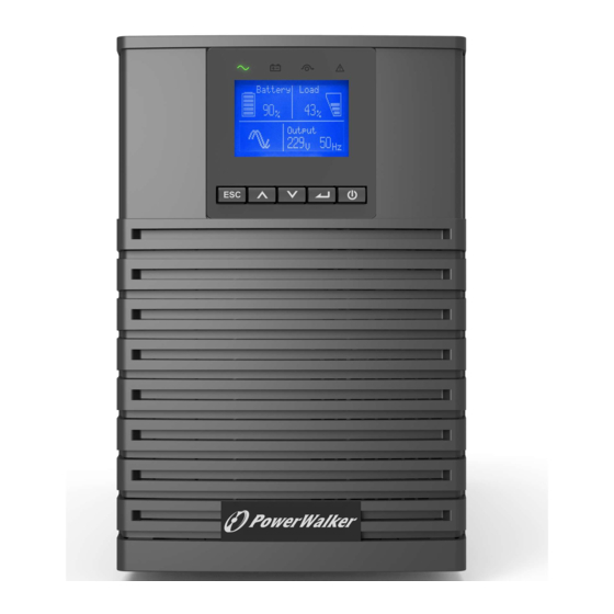
4 Betrieb LCD-Panel Das Display liefert nützliche Informationen über die USV selbst, den Laststatus, Ereignisse, Messungen und Einstellungen. Online-Modus- Störungsanzeige Anzeige (grün) (rot) Batteriemodus- Umgehung-Modus- Anzeige (orange) Anzeige (orange) Batterie Last 4 min Ausgang nach oben Nach unten Eingeben Ein/Aus-Taste Die nachfolgende Tabelle zeigt den Status und die Beschreibung des Anzeigers: Indikator Status...
Die nachfolgende Tabelle zeigt den Status und die Beschreibung der Anzeige: Taste Funktion Beschreibung Drücken der Taste für >100 ms & <1 Sek kann Aktivieren ohne Netzversorgung angeschlossener Batterie aktivieren. Wenn das Gerät aktiviert ist, kann durch Einschalten Drücken der Taste für >1 Sek die USV eingeschaltet werden.
Seite 64
Batterie-Status Last-/Ausrüstungsstatus Batterie Last 4 min Betriebsstatus Eingang/Ausgang- Ausgang Informationen Betriebsstatus Zustand Beschreibung Standby-Modus Die USV ist Aus ohne Ausgang. Online-Modus Die USV arbeitet normal und schützt die angeschlossenen Geräte. Eine Versorgungsstörung ist aufgetreten, und die Batterie-Modus USV versorgt die Ausrüstung aus der Batterie. 1 Piepton alle 4 Bereiten Sie Ihre angeschlossenen Geräte auf ein Sekunden...
Batteriefehler Die USV erkennt eine schlechte Batterie oder eine abgeklemmte Batterie Überlast Einige unnötige Lasten sollten abgetrennt werden, um die Belastung zu verringern. Störung-Modus Es gab ein/einige schwerwiegende(s) Problem(e). Anzeige-Funktionen Wenn die USV gestartet wird, erscheint der standardmäßige USV-Statuszusammenfassung-Bildschirm. Hauptmenü Untermenü...
Seite 66
Untermenü Verfügbare Einstellungen Standardeinstellungen Passwort Kann vom Benutzer geändert werden 4732 Englisch, Italienisch, Französisch, Deutsch, Sprache wechseln Englisch Spanisch, Russisch, Polnisch, 简体中文 Benutzer-Passwort [aktiviert, xxxx], [deaktiviert] aktiviert Akustische Alarme [aktiviert], [deaktiviert] aktiviert [230 V] Ausgangsspannung [200 V], [208 V], [220 V], [230 V], [240 V] [240 V] für AU Ausgangsfrequenz [Autoerkennung], [Wandler 50 Hz, 60 Hz]...
Inbetriebnahme der USV mit Netzversorgung Batterie Last Batterie Last WILLKOMME Ausgang Ausgang Eingestecktes Stromkabel Beginn 3 Sekunden Batterie Last Ausgang USV im Normalbetrieb Starten der USV im Batteriebetrieb Vor der Verwendung dieser Funktion muss die USV mindestens einmal mit Netzstrom versorgt worden sein und der Ausgang muss mindestens einmal aktiviert worden sein.
5 Kommunikation RS232 und USB- Kommunikationskabel zum seriellen oder USB-Anschluss des Computers. Schließen Sie das andere Ende des Kommunikationskabels an den RS232- oder USB-Kommunikationsanschluss der USV an. Fernsteuerungsfunktionen des USV Ferngesteuertes Ausschalten (RPO) Wenn RPO aktiviert ist, schaltet die USV den Ausgang sofort ab und setzt den Alarm fort.
Eingebauter Ethernet-Port und WLAN-Port (optionales Zubehör) ermöglichen marktführende und benutzerfreundliche IoT-Lösungen für: o WinPower View mobile App, mit der Sie die USV(s) fernüberwachen können und immer über kritische USV-Ereignisse informiert sind. o Fernmeldung von USV-Störungen und -Status (wenden Sie sich für Einzelheiten an Ihren Service) aus der APP oder einem registrierten APP- Account (E-Mail-Adresse) o Automatischer USV- und Batterie-Garantie Alarm aus der APP oder einem...
Protokolldetails an Ihren Service. Intelligente Kommunikationskarte (Optional) Die verschiedenen Kommunikationskarten Karte ermöglichen es der USV, mit verschiedenen Gerätetypen verschiedenen Netzwerkumgebungen kommunizieren. Für die PowerWalker VFI ICT/ICR IoT-Serie können die folgenden Kommunikationskarten verwendet werden. Bitte wenden Sie sich für...
USVs entfernt ist. Installationsverfahren: 1. Gehen Sie auf die Website:https://powerwalker.com/?page=winpower&lang=en 2. Wählen Sie das Betriebssystem, das Sie benötigen, und folgen Sie den Anweisungen auf der Website, um die Software herunterzuladen. 3. Bei der Installation fragt das Programm nach einer Seriennummer.
Seite 73
Installation fortzuführen. Wenn Sie die Installation beendet haben, starten Sie Ihren Computer neu, die WinPower-Software erscheint als grünes Steckersymbol in der Systemablage, in der Nähe der Uhr. 5.6.2 WinPower-View APP WinPower View ist eine mobile Anwendung, mit der Sie die mit der Cloud verbundene(n) USV(s) zentral überwachen können.
6 USV-Wartung 6.1 Pflege der Ausrüstung Für die beste vorbeugende Wartung halten Sie den Bereich um das Gerät herum sauber und staubfrei. Wenn die Umgebung sehr staubig ist, reinigen Sie die Außenseite des Systems regelmäßig mit einem Staubsauger. Um die volle Batterienutzungsdauer zu erreichen, sollten Sie die Geräte bei einer Umgebungstemperatur von 25°C (77°F) halten.
Halten Sie nicht autorisiertes Personal von den Batterien fern. Austausch der internen Batterie (Für RT) Legen Sie den neuen Akkupack in die USV ein. Schrauben Sie die Metallschutzabdeckungen und die Frontplatte wieder fest. Testen Sie die neue Batterie. Vergewissern Sie sich, dass die Ersatzbatterien denselben Nennwert und dieselbe Marke haben wie die auszutauschenden Batterien.
6.5 Wiederverwertung Wenden Sie sich an Ihr örtliches Recycling- oder Schadstoffzentrum, um Informationen zur ordnungsgemäßen Entsorgung der gebrauchten USV zu erhalten. Entsorgen Sie die Batterien nicht im Feuer. Dies kann zu einer Explosion der Batterien führen. Die Batterien müssen entsprechend den örtlichen Vorschriften ordnungsgemäß...
7 Fehlerbehebung Typische Alarme und Störungen: Um den USV-Status und das Ereignisprotokoll zu überprüfen: 1. Drücken Sie eine beliebige Taste auf der Anzeige an der Vorderseite um die Menüoptionen zu aktivieren. 2. Wählen Sie das Ereignisprotokoll aus und bestätigen Sie die Auswahl 3.
Seite 78
Bedingungen Mögliche Ursache Handlung Kundendienstvertreter. Umgehungs(Bypass)- Es ist eine Überlast oder eine Ausrüstung wird Strom Modus Störung eingetreten, oder es wurde versorgt, ist aber nicht durch die USV ein Befehl empfangen und die USV geschützt. Prüfen Sie, ob einer der befindet sich im Umgehung-Modus.
Bedingungen Mögliche Ursache Handlung die USV geht ein Bypass oder wird kontrollieren ausgeschaltet. Umgebungstemperatur. Kurzschluss am Ausgang Kurzschluss Ausgang Prüfen Sie den Ausgang der USV und aufgetreten die Lasten, stellen Sie sicher, dass der Kurzschluss vor dem Wiedereinschalten beseitigt wird. kann keine IoT ist deaktiviert...
Seite 80
>0,99 THDI <5% Steckdose (RT) 1x IEC C14 1x IEC C20 Eingangs- anschluss Steckdose (Tower) 1x IEC C14 1x IEC C20 1x Klemme Nennspannung 200/208/220/230/240 VAC (Ausgangsleistung reduziert um 10 % bei 208V und 20 % bei 200V) Nennfrequenz 50Hz/60Hz Maximaler PF PF = 1 Spannungsabweichung...
Seite 81
Anzeige Punktmatrix-LCD (optional Segment-LCD) Sprache Mehrsprachiges Menü USB 2,0 mit HID Funktion RS232 Ja (DB9) Potentialfreie Kontakte Je 1 programmierbarer potentialfreier Eingangs- und Ausgangskontakt ein/aus Steckkartenplatz Ja (für lange Karte) Netzwerkkarte Optional, NMC-Langkarte Modbus-Karte Optional, CMC-Langkarte Potentialfreie Kontakte Optional, AS400 Langkarte Karte Modul für kabellose Optional...
Seite 82
Series PowerWalker VFI ICT/ICR IoT GUIDE D’UTILISATION Service et assistance : Appelez votre représentant de service local...
CONSIGNES DE SÉCURITÉ CONSRVEZ CES CONSIGNES DE SÉCURITÉ. Le présent manuel contient d’importantes consignes lesquelles doivent être respectées lors de l’installation et la maintenance de l’onduleur (UPS) et des batteries. Les modèles d’UPS en Tour sont jugés acceptables à l’utilisation dans une température ambiante comprise entre 0°C et 45°C;...
La batterie livrée avec le système contient d’infimes quantités de matières toxiques. • Pour éviter des accidents, les directives énumérées ci-dessous doivent être respectées : L’entretien des batteries doit être effectué ou supervisé par un personnel bien informé au sujet des batteries et des précautions y relatives. Le risque d’explosion si la batterie est remplacée par une batterie inappropriée.
pour LES ÉQUIPEMENTS BRANCHÉS EN PERMANENCE, un dispositif de • déconnexion facile d’accès doit être intégré en externe à l’équipement. pour LES ÉQUIPEMENTS ENFICHABLES, le prise de courant doit être facile d’accès • et installée près de l’équipement Vérifiez que les indications sur la plaque signalétique correspondent à votre système •...
Seite 86
Table des matières Introduction ........................1 Protection des équipements électriques ............1 Protection environnementale ................2 Présentation du produit ....................3 Poids et Dimension ..................3 Panneaux arrières ..................... 5 Installation ........................9 Inspection de l’équipement ................9 Vérification de l’ensemble d’accessoires ............9 Installation de l’unité...
1 Introduction Merci d’avoir choisi l’unité IoT de l’UPS VFI ICT/ICR IoT pour protéger vos équipements électriques. Nous vous recommandons de prendre du temps et lire le présent guide pour en tirer le maximum d’avantage des nombreuses fonctionnalités de l’UPS (unité d’alimentation électrique sans interruption - onduleur).
Protection environnementale Les produits sont développés suivant une démarche d’éco-conception. Substances Le présent produit ne contient pas de CFC, HCFC ni d’asbestose. Emballage Pour améliorer le traitement des déchets et faciliter le recyclage, séparez les différentes composantes d’emballage. • Le carton que nous utilisons comprend plus de 50 % de carton recyclé. •...
2 Présentation du produit Poids et Dimension Les poids indiqués dans ce tableau sont à titre de référence. Veuillez consulter les étiquettes sur le carton pour avoir les détails. Modèles montés en tour : Description Poids nets (kg) Dimensions : P x L x H (mm) Tour 1K 12,8 404 X 145 X 220...
Seite 90
Modèles RT Description Poids nets (kg) Dimensions : P x L x H (mm) RT 1K 14,3 445*438*85,5 RT 1KS 445*438*85,5 RT 1,5K 15,8 445*438*85,5 RT 1,5KS 445*438*85,5 RT 2K 23,3 600*438*85,5 RT 2KS 10,6 600*438*85,5 RT 3K 26,2 600*438*85,5 RT 3KS 11,0 600*438*85,5...
3 Installation Inspection de l’équipement Si un quelconque équipement est endommagé au cours de l’expédition, conservez les cartons d’expédition et les matériaux d’emballage pour le transporteur ou le lieu d’achat, puis introduisez une plainte pour les dommages dus au transport. Si vous découvrez le dommage après la réception, introduisez une plainte pour dommage dissimulé.
Seite 96
Modèle RT Câbles de sortie Câble d’entrée Guide d’utilisation Câble USB Supports de tour (Anglais) Guide d’utilisation (en plusieurs langues (facultatif) Câble RS232(facultatif) Carte magnétique Ensemble Casiers à câble (facultative) (facultative) rails(facultatif)
Installation de l’unité Toujours garder un espace dégagé de 200 mm derrière le panneau arrière de l’UPS. Vérifier que les indications sur la plaque d’identification située au-dessus du couvercle de l’UPS correspondent à la source d’alimentation en CA ainsi qu’à la consommation électrique réelle de la charge totale.
Seite 98
Protection en amont recommandée Modèle d’UPS Disjoncteur en amont Tour 3KS Courbe C -20A Disjoncteur 2 pôles Vers la source d’entrée normale de l’UPS et/ou une source de CA de dérivation Connexion de la borne d’entrée et de la borne de sortie : ...
Seite 99
3.3.1 Modèles RT Installation de la baie Suivre les étapes 1 à 4 pour monter le module sur les rails.
Installation en tour Connexion des MBE(s) Un petit arc électrique peut se former lors de la connexion d’un MBE à l’UPS. C’est normal et cela ne fera de mal à personne. Jusqu’à 4 MBE peuvent être connectés à L’UPS. 3.4.1 Modèles en tour 1k/1,5k...
4 Fonctionnement Panneau LCD L’UPS fournit des renseignements utiles au sujet de l’UPS lui-même, l’état de charge, les évènements, les mesures et les paramètres. Indicateur du mode Indicateur en ligne (vert) d’anomalie (rouge) Indicateur du mode Indicateur du mode batterie (orange) dérivation (orange) Batterie Charge 4 min...
supplémentaires. Le tableau ci-dessous montre l’état de l’indicateur et la description : Le bouton Fonction Illustration Appuyer le bouton pendant >100ms et < 1s Mise sous tension peut allumer l’UPS sans tension d’entrée avec la batterie connectée Lorsque l’unité est mise sous tension, appuyer Mise en marche le bouton pendant >...
État de la batterie État de charge/de l’équipement Batterie Charge 4 min État de fonctionnement Information d’entrée/de sortie Sortie État de fonctionnement Cause Description Mode veille L’UPS est éteint sans puissance de sortie. Mode en ligne L’UPS fonctionne normalement et protège l’équipement.
Surcharge Des charges non nécessaires doivent être supprimées pour réduire la charge. Mode anomalie De graves soucis se sont produits. Fonctions d’affichage Lors du démarrage de l’UPS, l’affichage se trouve à l’état d’écran sommaire par défaut. Menu principal Menu secondaire Afficher les informations ou la fonction du menu Mode UPS, état IoT, date/heure ;...
Seite 106
Mot de passe de l’utilisateur [activé, ****], [désactivé] activé Alarmes audibles [activé], [désactivé] activé [230V] Tension de sortie [200V], [208V], [220V], [230V], [240V] [240V] pour AU [détection automatique], [convertisseur 50Hz, Fréquence de sortie détection automatique 60Hz] Mode haute efficacité [activé], [désactivé] désactivé...
4.5 Démarrage de l’UPS avec l’énergie électrique Batterie Charge Batterie Charge BIENVENU Sortie Sortie Cordon d’alimentation branché Démarrage 3 sec Batterie Charge Sortie UPS en mode normal Démarrage de l’UPS sur batterie Avant d’utiliser cette fonctionnalité, l’UPS doit avoir été alimenté par l’énergie électrique, la sortie ayant été...
5 Communication RS232 et USB- 1. Le câble de communication au port série ou USB sur l’ordinateur. 2. Connecter l’autre extrémité du câble de communication au RS232 ou au port de communication USB sur l’UPS. Fonctions de commande de l’UPS Désactivation à...
Type de connecteur 16 câbles AWG maximum Spécification du relais 24Vdc/1A interne Le port éthernet et le port WLAN (accessoire facultatif) intégrés offrent des solutions IoT innovantes et faciles d’usage pour : L’application mobile Winpower View qui permet de surveiller l’UPS à o...
- Veuillez utiliser le câble de réseau blindé CAT6. - La position du code QR sur l’UPS est à titre de référence, sous réserve de l’étiquette réelle de l’UPS. - Rassurez-vous que vos paramètres IT peuvent avoir accès au réseau public et à Microsoft Azure Cloud.
Le module sans fil est facultatif. Veuillez contacter votre distributeur local pour les détails Modbus TCP Le port éthernet intégré offre une fonctionnalité de Modbus TCP pour faciliter la surveillance à distance de l’UPS dans votre propre logiciel. Contacter votre service pour les détails de protocole.
Procédure d’installation : 1. Visiter le site Internet https://powerwalker.com/?page=winpower&lang=en 2. Choisir le système d’exploitation dont vous avez besoin et suivre l’instruction décrite sur le site Internet pour télécharger le logiciel. 3. Pendant le téléchargement de tous les fichiers requis à partir d’Internet, entrer le numéro de série : 511C1-01220-0100-478DF2A pour installer le logiciel.
6 Maintenance de l’UPS Entretien de l’équipement Pour une meilleure maintenance préventive, garder la zone autour de l’équipement propre et sans poussière. Si l’atmosphère est très poussiéreuse, nettoyer l’extérieur du système à l’aide d’un aspirateur. Pour une durée complète de la batterie, garder l’équipement à une température ambiante de 25°C (77°F).
Seite 116
bonne connaissance des batteries, ainsi que des précautions exigées. Ternir le personnel non autorisé éloigné des batteries. Remplacement de la batterie interne (pour RT) • 1. Placer le nouveau bloc batterie dans l’UPS. 2. Desserrer les couvercles de protection métallique et le panneau avant. 3.
remplacées. Recyclage Contactez votre centre local de recyclage ou traitement de déchets dangereux pour obtenir des renseignements relatifs à l’élimination correcte des équipements utilisés. N’éliminez pas les batteries dans le feu. Ceci peut causer une explosion de la batterie. Les batteries doivent être éliminées de manière appropriée, conformément à...
7 Dépannage Alarmes ordinaires et anomalies : Pour vérifier l’état de l’UPS et le journal des évènements : 1. Appuyer n’importe quel bouton sur l’afficheur du panneau avant pour activer les options du menu. 2. Appuyer le bouton pour sélectionner le journal des évènements. 3.
Seite 119
Cause possible Action Conditions Charger les batteries à l’énergie L’UPS ne fournit pas la Les batteries nécessitent la électrique pendant 48 heures. Si cette durée de sauvegarde recharge ou l’entretien. situation persiste, contactez votre attendue. représentant de service. Une surcharge ou une anomalie L’équipement est alimenté...
Cause possible Action Conditions dérivation ou est arrêté. Court-circuit en sortie Le court-circuit en sortie s’est Vérifier la sortie de l’UPS et les produit charges. Se rassurer que le court-circuit est retiré avant un nouvel allumage. L’application ne peut pas IoT est désactivé...
Seite 121
d’entrée Douille (Tour) 1x IEC C14 1x IEC C20 1x Terminal 200/208/220/230/240 VAC (réduction de puissance à 10 % à 208V, réduction de puissance à Tension nominale 20 % à 200V) Fréquence nominale 50Hz/60Hz PF maximal PF = 1 Précision de tension ±1% THDv <1 % de charge linéaire ;...
Seite 122
Langue Plusieurs langues USB 2,0 avec un dispositif d’alimentation HID RS232 Oui (DB9) Entrée/Sortie à contact 1 Entrée à contact sec programmable ; 1 Sortie à contact sec programmable Créneau intelligent Oui (pour de longue carte) Carte réseau Facultative, carte longue NMC Carte Modbus Facultative, carte longue CMC Carte du contacteur...