Herunterladen Diese Seite drucken
Dimplex SI 10MER Montage- Und Gebrauchsanweisungen

Dimplex SI 10MER Montage- Und Gebrauchsanweisungen

Sole-wasser-wärmepumpe für innenaufstellung
Vorschau ausblenden Andere Handbücher für SI 10MER:

Werbung

Verfügbare Sprachen

Verfügbare Sprachen

SI 10MER
Montage- und
Gebrauchsanweisung
Sole-Wasser-
Wärmepumpe
für Innenaufstellung
Bestell-Nr. | Order no. | No de commande: 452232.66.41
Installation and
Operating Instruction
Brine-to-Water
Heat Pump for
Indoor Installation
Glen
Dimplex
Thermal
Solutions
Instuctions d'installation
et d'utilisation
Pompe à chaleur
eau glyclée-eau pour
installation intérieure
DE | EN | FR · FD 9912
Dimplex

Werbung

loading

Inhaltszusammenfassung für Dimplex SI 10MER

  • Seite 1 Glen Dimplex Thermal Solutions Dimplex SI 10MER Montage- und Installation and Instuctions d‘installation Gebrauchsanweisung Operating Instruction et d‘utilisation Sole-Wasser- Brine-to-Water Pompe à chaleur Wärmepumpe Heat Pump for eau glyclée-eau pour für Innenaufstellung Indoor Installation installation intérieure Bestell-Nr. | Order no. | No de commande: 452232.66.41...
  • Seite 3: Inhaltsverzeichnis

    SI 10MER Deutsch Inhaltsverzeichnis Bitte sofort lesen ............................DE-2 1.1 Wichtige Hinweise ................................DE-2 1.2 Bestimmungsgemäßer Gebrauch ..........................DE-2 1.3 Gesetzliche Vorschriften und Richtlinien.........................DE-2 1.4 Energiesparende Handhabung der Wärmepumpe ....................DE-2 Verwendungszweck der Wärmepumpe ....................DE-3 2.1 Anwendungsbereich...............................DE-3 2.2 Arbeitsweise..................................DE-3 Grundgerät..............................DE-3 Zubehör .................................DE-4 4.1 Soleverteiler ..................................DE-4 4.2 Fernbedienung..................................DE-4...
  • Seite 4: Bitte Sofort Lesen

    Deutsch SI 10MER gehender Gebrauch gilt als nicht bestimmungsgemäß. Dazu Bitte sofort lesen zählt auch die Beachtung der zugehörigen Projektierungsun- terlagen. Änderungen oder Umbauten am Gerät sind zu unter- 1.1 Wichtige Hinweise lassen. 1.3 Gesetzliche Vorschriften und ACHTUNG! Für den Betrieb und die Wartung einer Wärmepumpe sind die...
  • Seite 5: Verwendungszweck Der Wärmepumpe

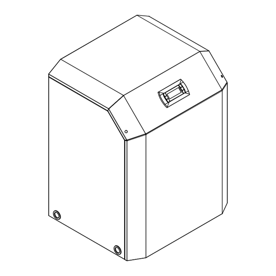
    SI 10MER Deutsch Verwendungszweck der Grundgerät Wärmepumpe Das Grundgerät besteht aus einer anschlussfertigen Wärme- pumpe für Innenaufstellung mit Blechgehäuse, Schaltkasten und integriertem Wärmepumpenmanager. Der Kältekreis ist 2.1 Anwendungsbereich „hermetisch geschlossen“ und enthält das vom Kyoto-Protokoll erfasste fluorierte Kältemittel R410A. Angaben zum GWP-Wert Die Sole/Wasser-Wärmepumpe ist ausschließlich für die Erwär-...
  • Seite 6: Zubehör

    Deutsch SI 10MER Zubehör 4.1 Soleverteiler Der Soleverteiler vereinigt die Kollektorschleifen der Wärme- quellenanlage zu einer Hauptleitung, welche an die Wärme- pumpe angeschlossen wird. Mittels der integrierten Kugel- hähne können zum Entlüften einzelne Solekreise abgesperrt werden. Abb. 4.1: Raumklimastation 4.5 Wärmemengenzähler WMZ 4.5.1 Allgemeine Beschreibung...
  • Seite 7: Transport

    SI 10MER Deutsch Transport Aufstellung Zum Transport auf ebenem Untergrund eignet sich ein Hubwa- 6.1 Allgemeine Hinweise gen. Muss die Wärmepumpe auf unebenem Untergrund oder über Treppen befördert werden, kann dies mit Tragriemen ge- Die Sole/Wasser-Wärmepumpe muss in einem frostfreien und schehen.
  • Seite 8: Montage

    Deutsch SI 10MER Mindestheizwasserdurchsatz Montage Der Mindestheizwasserdurchsatz der Wärmepumpe ist in jedem Betriebszustand der Heizungsanlage sicherzustellen. 7.1 Allgemein Dieses kann z.B. durch Installation eines doppelt differenz- drucklosen Verteilers oder eines Überströmventiles erreicht An der Wärmepumpe sind folgende Anschlüsse herzustellen: werden. Die Einstellung eines Überströmventiles ist in Kapitel Vor-/Rücklauf Sole (Wärmequellenanlage)
  • Seite 9: Temperaturfühler

    SI 10MER Deutsch 7.4 Temperaturfühler 7.4.2 Montage des Außentemperaturfühlers Folgende Temperaturfühler sind bereits eingebaut bzw. müs- sen zusätzlich montiert werden: Der Temperaturfühler muss so angebracht werden, dass sämt- liche Witterungseinflüsse erfasst werden und der Messwert  Außentemperatur (R1) beigelegt (NTC-2) nicht verfälscht wird.
  • Seite 10: Verteilsystem Hydraulik

    Deutsch SI 10MER 7.4.4 Verteilsystem Hydraulik Die 3-adrige elektrische Versorgungsleitung für den Wärmepumpenmanager (Heizungsregler N1) wird in die Kompaktverteiler und Doppelt differenzdruckloser Verteiler Wärmepumpe geführt. Anschluss der Steuerleitung am fungieren als Schnittstelle zwischen der Wärmepumpe, dem Schaltkasten der Wärmepumpe über Klemmen X2: L/N/ Heizungsverteilsystem, dem Pufferspeicher und evtl.
  • Seite 11: Anschluss Von Elektronisch Geregelten Umwälzpumpen

    SI 10MER Deutsch 8.3 Vorgehensweise bei 7.5.3 Anschluss von elektronisch geregelten Umwälzpumpen Inbetriebnahme Elektronisch geregelte Umwälzpumpen weisen hohe Anlauf- Die Inbetriebnahme der Wärmepumpe erfolgt über den ströme auf, die unter Umständen die Lebenszeit des Wärme- Wärmepumpenmanager. pumpenmanagers verkürzen können. Aus diesem Grund, ist zwischen dem Ausgang des Wärmepumpenmanagers und der...
  • Seite 12: Pflege / Reinigung

    Deutsch SI 10MER Pflege / Reinigung 10 Störungen / Fehlersuche Diese Wärmepumpe ist ein Qualitätsprodukt und sollte stö- 9.1 Pflege rungsfrei arbeiten. Tritt dennoch eine Störung auf, wird dies im Display des Wärmepumpenmanagers angezeigt. Schlagen Sie Um Betriebsstörungen durch Schmutzablagerungen in den dazu auf der Seite Störungen und Fehlersuche in der Ge-...
  • Seite 13: Geräteinformation

    SI 10MER Deutsch 12 Geräteinformation Typ- und Verkaufsbezeichnung SI 10MER Bauform Ausführung Reversibel Schutzart nach EN 60 529 IP 21 Aufstellungsort Innen Leistungsangaben Temperatur-Betriebseinsatzgrenzen: +20 bis +62 ±2 Heizwasser-Vorlauf °C Kühlen, Vorlauf °C +7 bis +20 Sole (Wärmequelle, Heizen) °C bis +25 Sole (Wärmesenke, Kühlen)
  • Seite 14 Deutsch SI 10MER Entspricht den europäischen Sicherheitsbestimmungen Sonstige Ausführungsmerkmale Wasser im Gerät gegen Einfrieren geschützt Leistungsstufen Regler intern / extern intern max. Betriebsüberdruck (Wärmequelle/Wärmesenke) 1. Diese Angaben charakterisieren die Größe und Leistungsfähigkeit der Anlage nach EN 14511. Für wirtschaftliche und energetische Betrachtungen sind Bivalenzpunkt und Re- gelung zu berücksichtigen.
  • Seite 15: Produktinformationen Gemäß Verordnung (Eu) Nr.813/2013, Anhang Ii, Tabelle 2

    Kontakt Glen Dimplex Deutschland GmbH, Am Goldenen Feld 18, 95326 Kulmbach (*) Für Heizgeräte und Kombiheizgeräte mit Wärmepumpe ist die Wärmenennleistung Prated gleich der Auslegungslast im Heizbetrieb Pdesingh und die Wärmenennleistung eines Zusatzheizgerätes Psup gleich der zusaätzlichen Heizleistung sup(Tj ).
  • Seite 16: Garantieurkunde

    Wahl instandgesetzt oder durch einwandfreie Teile Die aktuellen Pauschalen und die damit verbundenen Leistungs- ersetzt werden. Durch Art oder Ort des Einsatzes des Gerätes oder umfänge sind im Internet unter: http://www.dimplex.de/garantie- schlechte Zugänglichkeit des Gerätes bedingte außergewöhnliche verlaengerung hinterlegt. Hier ist ebenfalls eine Online-Beauftra- Kosten der Nachbesserung werden nicht übernommen.
  • Seite 17 SI 10MER English Table of contents Please Read Immediately ..........................EN-2 1.1 Important Information ..............................EN-2 1.2 Intended Use ..................................EN-2 1.3 Legal Regulations and Directives ..........................EN-2 1.4 Energy-Efficient Use of the Heat Pump ........................EN-2 Purpose of the Heat Pump........................EN-3 2.1 Application ..................................EN-3 2.2 Operating Principle................................EN-3...
  • Seite 18: Please Read Immediately

    English SI 10MER 1.2 Intended Use Please Read Immediately This device is only intended for use as specified by the manu- 1.1 Important Information facturer. Any other use beyond that intended by the manufac- turer is prohibited. This requires the user to abide by the rele- vant project planning documents.
  • Seite 19: Purpose Of The Heat Pump

    SI 10MER English Purpose of the Heat Pump Basic Device The basic device consists of a heat pump for indoor installation 2.1 Application wired ready for use with metal casing, switch box and inte- grated heat pump manager. The refrigeration circuit is "hermet- The brine-to-water heat pump is to be used exclusively for the ically sealed"...
  • Seite 20: Accessories

    English SI 10MER Accessories 4.1 Brine Circuit Manifold The brine circuit manifold merges the individual collector loops of the heat source system into a single main pipe which is con- nected to the heat pump. Integrated ball valves allow the indi- vidual brine circuits to be shut off for de-aeration purposes.
  • Seite 21: Transport

    SI 10MER English Transport Set-up A lift truck is suited for transporting the unit on a level surface. 6.1 General Information Carrying straps may be used if the heat pump needs to be transported on an uneven surface or carried up or down stairs.
  • Seite 22: Installation

    English SI 10MER Minimum heating water flow rate Installation The minimum heating water flow rate through the heat pump must be assured in all operating states of the heating system. 7.1 General Information This can be accomplished, for example, by installing either a dual differential pressureless manifold or an overflow valve.
  • Seite 23: Temperature Sensor

    SI 10MER English 7.4 Temperature sensor 7.4.2 Mounting the external temperature sensor The following temperature sensors are already installed or must be installed additionally: The temperature sensor must be mounted in such a way that all weather conditions are taken into consideration and the meas- ...
  • Seite 24: Electrical Connection

    English SI 10MER 7.4.4 Hydraulic distribution system The three-core electric supply cable for the heat pump manager (heating controller N1) is fed into the heat pump . The compact manifold and the dual differential pressureless Connection of the control line to the switch box of the heat manifold function as an interface between the heat pump, the pump via terminal X2: L/N/PE.
  • Seite 25: Connecting An Electronically Regulated Circulating Pump

    SI 10MER English 8.3 Start-up Procedure 7.5.3 Connecting an electronically regulated circulating pump The heat pump is started up via the heat pump manager. Electronically regulated circulating pumps have high starting ATTENTION! currents, which may shorten the service life of the heat pump The heat pump must be started up in accordance with the manager.
  • Seite 26: Maintenance And Cleaning

    English SI 10MER Maintenance and Cleaning 10 Faults / Trouble-Shooting This heat pump is a quality product and is designed for trouble- 9.1 Maintenance free operation. In the event that a fault should occur, it will be indicated on the heat pump manager display. Simply consult...
  • Seite 27: Device Information

    SI 10MER English 12 Device Information Type and order code SI 10MER Design Model Reversible Degree of protection according to EN 60 529 IP 21 Installation location Indoors Performance data Operating temperature limits: +20 to +62 ±2 Heating water flow °C...
  • Seite 28 English SI 10MER Complies with the European safety regulations Additional model features Water in device protected against freezing Performance levels Controller internal/external internal Max. operating overpressure (heat source/heat sink) 1. These data indicate the size and capacity of the system according to EN 14511. For an analysis of the economic and energy efficiency of the system, the bivalence point and controller should be taken into consideration.
  • Seite 29: Product Information As Per Regulation (Eu) No 813/2013, Annex Ii, Table 2

    Contact details Glen Dimplex Deutschland GmbH, Am Goldenen Feld 18, 95326 Kulmbach (*) For heat pump space heaters and heat pump combination heaters, the rated output Prated is equal to the design load for heating Pdesignh , and the rated heat output of a supplementary capacity for heating sup(Tj ).
  • Seite 30 English SI 10MER EN-14 452232.66.41 · FD 9912 www.gdts.one...
  • Seite 31 SI 10MER Français Table des matières A lire immédiatement !..........................FR-2 1.1 Remarques importantes ..............................FR-2 1.2 Utilisation conforme................................ FR-2 1.3 Dispositions légales et directives..........................FR-2 1.4 Utilisation de la pompe à chaleur pour économiser de l'énergie..............FR-3 Utilisation de la pompe à chaleur ......................FR-3 2.1 Domaine d’utilisation ..............................
  • Seite 32: Lire Immédiatement

    Français SI 10MER 1.2 Utilisation conforme A lire immédiatement ! Cet appareil ne doit être employé que selon les conditions d'uti- 1.1 Remarques importantes lisation prévues par le fabricant. Toute autre utilisation est considérée comme non conforme. La documentation accom- pagnant les projets doit également être prise en compte.
  • Seite 33: Utilisation De La Pompe À Chaleur Pour Économiser De L'énergie

    SI 10MER Français 1.4 Utilisation de la pompe à Refroidissement En mode refroidissement, le mode de fonctionnement de l’éva- chaleur pour économiser de porateur et du condenseur est inversé. l'énergie L’eau de chauffage délivre de la chaleur au fluide frigorigène via le condenseur qui fonctionne désormais en tant qu’évapora-...
  • Seite 34: Accessoires

    Français SI 10MER Station de climatisation de pièce Accessoires Lors du rafraîchissement via un système de chauffage/ rafraî- 4.1 Distributeur d'eau glycolée chissement par surfaces, la régulation a lieu en fonction de la température ambiante mesurée au niveau de la station de cli- Le distributeur d’eau glycolée réunit les boucles du collecteur...
  • Seite 35: Transport

    SI 10MER Français 4.5.2 Intégration hydraulique et électrique Installation du calorimètre 6.1 Généralités Le calorimètre a besoin de deux dispositifs de mesure pour sai- sir les données. N'installer l'appareil qu'à l'intérieur, dans des pièces non hu-  Un tube de mesure du débit mides sur une surface plane, lisse et horizontale.
  • Seite 36: Branchement Côté Installation De Chauffage

    Français SI 10MER 7.2 Branchement côté installation Débit d'eau de chauffage minimum Le débit minimum d'eau de chauffage doit être garanti dans la de chauffage pompe à chaleur quel que soit l'état de fonctionnement de l'ins- tallation de chauffage. C'est tout à fait réalisable en montant un ATTENTION ! distributeur double sans pression différentielle ou une soupape...
  • Seite 37: Sonde De Température

    SI 10MER Français 7.4 Sonde de température  ne pas monter dans un « emplacement protégé » (par ex. dans la niche d’un mur ou sous le balcon), Les sondes de températures suivantes sont déjà montées ou ne pas installer à proximité de fenêtres, portes, ouvertures ...
  • Seite 38: Branchements Électriques

    Français SI 10MER 7.5 Branchements électriques Le contacteur (K20) de la résistance immergée (E10) doit être dimensionné, sur les installations mono-énergétiques (2ème générateur de chaleur) en fonction de la puissance 7.5.1 Généralités de la résistance et fourni par le client. La commande (230 V AC) s’effectue à...
  • Seite 39: Mise En Service

    SI 10MER Français 8.3 Procédures à suivre lors de la Mise en service mise en service 8.1 Généralités La mise en service de la pompe à chaleur s’effectue via le ges- tionnaire de pompe à chaleur. Pour garantir une mise en service en règle, cette dernière doit être effectuée par un service après-vente agréé...
  • Seite 40: Entretien / Nettoyage

    Français SI 10MER Entretien / nettoyage 10 Défaillances / recherche de pannes 9.1 Entretien Cette pompe à chaleur est un produit de qualité. Si un dysfonc- Pour éviter des dysfonctionnements dus à des dépôts dans les tionnement devait quand même survenir, celui-ci sera affiché...
  • Seite 41: Informations Sur Les Appareils

    SI 10MER Français 12 Informations sur les appareils Désignation technique et commerciale SI 10MER Forme Version Réversible Type de protection selon EN 60 529 IP 21 Emplacement en intérieur Indications de puissance Température - limites d’exploitation : de +20 à +62 ±2 Départ eau de chauffage...
  • Seite 42 Français SI 10MER Courant de démarrage avec démarreur progressif Courant nominal B0 W35 / cos A / --- 10,4 / 0,95 Conforme aux dispositions de sécurité européennes Autres caractéristiques techniques Eau de chauffage dans l’appareil protégée du gel Niveaux de puissance Régulateur interne / externe...
  • Seite 43: Informations Sur Le

    Glen Dimplex Deutschland GmbH, Am Goldenen Feld 18, 95326 Kulmbach Coordonnées de contact (*) Pour les dispositifs de chauffage des locaux par pompe à chaleur et les dispositifs de chauffage mixtes par pompe à chaleur, la puissance thermique nominale Prated est égale à...
  • Seite 44 Français SI 10MER FR-14 452232.66.41 · FD 9912 www.gdts.one...
  • Seite 45: Anhang / Appendix / Annexes

    SI 10MER Anhang · Appendix · Annexes Anhang / Appendix / Annexes Maßbilder / Dimension Drawings / Schémas cotés ................A-II 1.1 Maßbild / Dimension Drawing / Schéma coté......................A-II Diagramme / Diagrams / Diagrammes ....................A-III 2.1 Kennlinie Heizbetrieb / Characteristic curves for heating operation / Courbes caractéristiques mode chauffage....................................A-III...
  • Seite 46: Maßbilder / Dimension Drawings / Schémas Cotés

    Anhang · Appendix · Annexes SI 10MER 1 Maßbilder / Dimension Drawings / Schémas cotés 1.1 Maßbild / Dimension Drawing / Schéma coté A-II 452232.66.41 · FD 9912 www.gdts.one...
  • Seite 47: Diagramme / Diagrams / Diagrammes

    SI 10MER Anhang · Appendix · Annexes 2 Diagramme / Diagrams / Diagrammes 2.1 Kennlinie Heizbetrieb / Characteristic curves for heating operation / Courbes caractéristiques mode chauffage Heizleistung in [kW] Wasseraustrittstemperatur in [°C] Heating capacity in [kW] Water outlet temperature in [°C] Puissance de chauffage en [kW] Température de sortie de l'eau en [°C]...
  • Seite 48: Kennlinie Kühlbetrieb / Characteristic Curve Cooling Operation / Courbes Caractéristiques Mode Refroidissement

    Anhang · Appendix · Annexes SI 10MER 2.2 Kennlinie Kühlbetrieb / Characteristic curve cooling operation / Courbes caractéristiques mode refroidissement Kühlleistung in [kW] Wasseraustrittstemperatur in [°C] Cooling capacity in [kW] Water outlet temperature in [°C] Température de sortie de l'eau en [°C] Puissance de refroidissement en [kW] Bedingungen ·...
  • Seite 49: Einsatzgrenzendiagramm Heizen / Operating Limits Diagram Heating / Diagramme Des Seuils D'utilisation Chauffage

    SI 10MER Anhang · Appendix · Annexes 2.3 Einsatzgrenzendiagramm Heizen / Operating limits diagram heating / Diagramme des seuils d'utilisation chauffage Wasseraustritt (+/- 2 K) Water outlet (+/- 2 K) Sortie d'eau (+/- 2 K) Wärmequelleneintrittstemperatur [°C] Heat source inlet temperature [°C] Température d'entrée de la source de chaleur [°C]...
  • Seite 50: Einsatzgrenzendiagramm Kühlen / Operating Limits Diagram Cooling / Diagramme Des Seuils D'utilisation Rafraîchissement

    Anhang · Appendix · Annexes SI 10MER 2.4 Einsatzgrenzendiagramm Kühlen / Operating limits diagram cooling / Diagramme des seuils d'utilisation rafraîchissement Wasseraustritt (+/- 2 K) Water outlet (+/- 2 K) Sortie d'eau (+/- 2 K) Wärmesenkeneintrittstemperatur [°C] Heat sink inlet temperature [°C] Température d'entrée de dissipation thermique [°C]...
  • Seite 51: Stromlaufpläne / Circuit Diagrams / Schémas Électriques

    SI 10MER Anhang · Appendix · Annexes 3 Stromlaufpläne / Circuit Diagrams / Schémas électriques 3.1 Steuerung Standardregler / Control via the standard controller / Commande régulateur standard www.gdts.one 452232.66.41 · FD 9912 A-VII...
  • Seite 52: Steuerung Kühlregler / Control Via The Cooling Controller / Commande Régulateur Refroidissement

    Anhang · Appendix · Annexes SI 10MER 3.2 Steuerung Kühlregler / Control via the cooling controller / Commande régulateur refroidissement A-VIII 452232.66.41 · FD 9912 www.gdts.one...
  • Seite 53: Last / Load / Charge

    SI 10MER Anhang · Appendix · Annexes 3.3 Last / Load / Charge www.gdts.one 452232.66.41 · FD 9912 A-IX...
  • Seite 54: Anschlussplan Standardregler / Terminal Diagram For Standard Controller / Schéma De Branchement Du Régulateur Standard

    Anhang · Appendix · Annexes SI 10MER 3.4 Anschlussplan Standardregler / Terminal diagram for standard controller / Schéma de branchement du régulateur standard 452232.66.41 · FD 9912 www.gdts.one...
  • Seite 55: Anschlussplan Kühlregler / Terminal Diagram For Cooling Controller / Schéma De Branchement Du Régulateur De Refroidissement

    SI 10MER Anhang · Appendix · Annexes 3.5 Anschlussplan Kühlregler / Terminal diagram for cooling controller / Schéma de branchement du régulateur de refroidissement www.gdts.one 452232.66.41 · FD 9912 A-XI...
  • Seite 56: Legende / Legend / Légende

    Anhang · Appendix · Annexes SI 10MER 3.6 Legende / Legend / Légende Brücke EVU-Sperre, muss eingelegt werden, Utility block (EVU) bridge must be inserted if no Pont de blocage de la société d'électricité, à insérer wenn kein EVU-Sperrschütz vorhanden ist utility blocking contactor is present en absence de contacteur de blocage de la société...
  • Seite 57 SI 10MER Anhang · Appendix · Annexes Vorlauffühler Primärkreis Flow sensor for primary circuit Sonde aller circuit primaire Codierwiderstand 19k6 Coding resistor 19.6 kOhm Résistance de codage 19k6 Frostschutzfühler Kühlen Flow sensor, cooling Sonde antigel refroidissement Vorlauffühler Heizkreis Flow sensor for heating circuit...
  • Seite 58: Hydraulisches Einbindungsschema / Hydraulic Integration Diagram / Schéma D'intégration Hydraulique

    Anhang · Appendix · Annexes SI 10MER 4 Hydraulisches Einbindungsschema / Hydraulic integration diagram / Schéma d’intégration hydraulique 4.1 Monoenergetische Anlage mit dynamischer Kühlung und Warmwasserbereitung / Mono energy system with dynamic cooling and domestic hot water preparation /Installation mono-énergétique avec rafaîchissemant dynamique et production d'eau chaude sanitaire...
  • Seite 59: Legende / Legend / Légende

    SI 10MER Anhang · Appendix · Annexes 4.2 Legende / Legend / Légende Rückschlagventil Check valve Clapet anti-retour Absperrventil Shutoff valve Robinet d’arrêt Schmutzfänger Dirt trap Filtre Umwälzpumpe Circulating pump Circulateur Ausdehnungsgefäß Expansion vessel Vase d´expansion Vanne commandée par Raumtemperaturgesteuertes Ventil Room temperature-controlled valve température ambiante...
  • Seite 60: Konformitätserklärung / Declaration Of Conformity / Déclaration De Conformité

    Anhang · Appendix · Annexes SI 10MER 5 Konformitätserklärung / Declaration of Conformity / Déclaration de conformité Die aktuelle CE-Konformitätserklärung finden sie als Download unter: You can find and download the current CE conformity declaration at: Vous pouvez télécharger la déclaration de conformité CE actuelle sous : https://gdts.one...
  • Seite 61 SI 10MER Anhang · Appendix · Annexes www.gdts.one 452232.66.41 · FD 9912 A-XVII...
  • Seite 62 Anhang · Appendix · Annexes SI 10MER A-XVIII 452232.66.41 · FD 9912 www.gdts.one...
  • Seite 63 SI 10MER Anhang · Appendix · Annexes www.gdts.one 452232.66.41 · FD 9912 A-XIX...
  • Seite 64 Glen Dimplex Deutschland GmbH Irrtümer und Änderungen vorbehalten. Geschäftsbereich GDTS Subject to alterations and errors. Am Goldenen Feld 18 Sous réserve d’erreurs et modifications. D-95326 Kulmbach +49 (0) 9221 709 924545 www.gdts.one...