Dimplex SI 5US Gebrauchsanweisung
Verfügbare Sprachen
Verfügbare Sprachen
Quicklinks
SI 5US
SI 7US
SI 9US
SI 11US
SI 14US
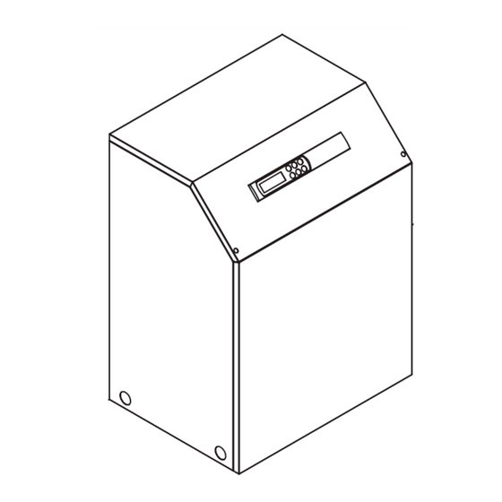
Sole/Wasser-
Wärmepumpe für
Innenaufstellung
Bestell-Nr. / Order no. / N
Brine-to-Water
Heat Pump for
Indoor Installation
o
de commande : 452232.66.01
Montage- und
Gebrauchsanweisung
Installation and
Operating Instructions
Instructions d'installation
et d'utilisation
Pompe à chaleur
eau glycolée-eau
pour installation
intérieure
FD 8611
Kapitel

Verwandte Anleitungen für Dimplex SI 5US


Inhaltszusammenfassung für Dimplex SI 5US
- Seite 1 SI 5US SI 7US SI 9US Montage- und SI 11US Gebrauchsanweisung SI 14US Installation and Operating Instructions Instructions d’installation et d’utilisation Sole/Wasser- Brine-to-Water Pompe à chaleur Wärmepumpe für Heat Pump for eau glycolée-eau Innenaufstellung Indoor Installation pour installation intérieure Bestell-Nr. / Order no. / N de commande : 452232.66.01...
-
Seite 3: Inhaltsverzeichnis
Pflege / Reinigung ........................D-6 9.1 Pflege..............................D-6 9.2 Reinigung Heizungsseite ........................D-6 9.3 Reinigung Wärmequellenseite........................D-6 10 Störungen / Fehlersuche ......................D-6 11 Außerbetriebnahme / Entsorgung ....................D-6 12 Geräteinformation ........................D-7 13 Garantieurkunde........................... D-8 Anhang / Appendix / Annexes ......................A-I www.dimplex.de... -
Seite 4: Bitte Sofort Lesen
Bitte sofort lesen 1.2 Gesetzliche Vorschriften und Richtlinien 1.1 Wichtige Hinweise Die Wärmepumpe entspricht allen relevanten DIN-/VDE-Vor- schriften und EG-Richtlinien. Diese können der CE-Erklärung im ACHTUNG! Anhang entnommen werden. Die Wärmepumpe ist nicht am Holzrost befestigt. Der elektrische Anschluss der Wärmepumpe muss nach den gül- tigen VDE-, EN- und IEC-Normen ausgeführt werden. -
Seite 5: Grundgerät
Zum Anheben des Gerätes ohne Palette sind die seitlich im Rah- men vorgesehenen Bohrungen zu benutzen. Die seitlichen Ver- kleidungsbleche sind dabei abzunehmen. Als Tragehilfe kann ein handelsübliches Rohr dienen. ACHTUNG! Gerät nicht an den Bohrungen in den Verkleidungsblechen anheben! www.dimplex.de... -
Seite 6: Aufstellung
Aufstellung Montage 6.1 Allgemeine Hinweise 7.1 Allgemein Das Gerät ist grundsätzlich in Innenräumen auf einer ebenen, An der Wärmepumpe sind folgende Anschlüsse herzustellen: glatten und waagrechten Fläche aufzustellen. Dabei sollte der Vor-/Rücklauf Soleanlage Rahmen rundum dicht am Boden anliegen, um eine geeignete Vor-/Rücklauf Heizung Schallabdichtung zu gewährleisten. -
Seite 7: Elektrischer Anschluss
Der Schmutzfänger muss im Soleeintritt der Wärmepumpe eingebaut sein. Im Sole- und Heizkreislauf müssen alle Schieber, die den korrekten Fluss behindern könnten, geöffnet sein. Der Wärmepumpenregler muss gemäß seiner Gebrauchs- anweisung auf die Heizungsanlage abgestimmt sein. www.dimplex.de... -
Seite 8: Pflege / Reinigung
Pflege / Reinigung 10 Störungen / Fehlersuche Diese Wärmepumpe ist ein Qualitätsprodukt und sollte störungs- 9.1 Pflege frei arbeiten. Tritt dennoch eine Störung auf, wird diese im Dis- play des Wärmepumpenmanagers angezeigt. Schlagen Sie Die Wärmepumpe arbeitet wartungsfrei. Um Betriebsstörungen dazu auf der Seite Störungen und Fehlersuche in der Ge- durch Schmutzablagerungen in den Wärmeaustauschern zu ver- brauchsanweisung des Wärmepumpenmanagers nach. -
Seite 9: Geräteinformation
12 Geräteinformation Geräteinformation für Sole/Wasser-Heiz-Wärmepumpen Typ- und Verkaufsbezeichnung SI 5US SI 7US SI 9US SI 11US SI 14US Bauform Schutzart nach EN 60 529 IP 20 IP 20 IP 20 IP 20 IP 20 Aufstellungsort Innen Innen Innen Innen Innen... -
Seite 10: Garantieurkunde
Teile ersetzt werden. Durch Art oder Ort des Einsatzes des Systemtechnik-Kundendienst erfahren Sie über die zentrale Ser- Gerätes oder schlechte Zugänglichkeit des Gerätes bedingte au- vicehotline der Glen Dimplex Deutschland GmbH. ßergewöhnliche Kosten der Mängelbeseitigung werden nicht übernommen. Der freie Gerätezugang muss durch den Endab- Glen Dimplex Deutschland GmbH nehmer gestellt werden. -
Seite 35: Last / Load / Charge
3.2 Last / Load / Charge www.dimplex.de A-IX... -
Seite 37: Legende / Legend / Légende
Heat pump controller Régulateur de pompe à chaleur Sanftanlaufsteuerung (nicht in SI 5US und SI 7US Soft start control (not in SI 5US and SI 7US) Commande de démarrage progressif (ne concerne Geräten pas les appareils SI 5US et SI 7US) -
Seite 38: Hydraulisches Prinzipschema / Hydraulic Plumbing Diagram / Schéma Hydraulique
4 Hydraulisches Prinzipschema / Hydraulic Plumbing Diagram / Schéma hydraulique 4.1 Darstellung / Schematic View / Représentation A-XII... -
Seite 39: Legende / Legend / Légende
Hot water circulating pump Circulateur d’eau chaude Außenwandfühler External wall sensor Sonde extérieure Rücklauffühler Return flow sensor Sonde circuit retour Warmwasserfühler Hot water sensor Sonde d’eau chaude sanitaire Kaltwasser Cold water Eau froide Warmwasser Domestic hot water Eau chaude www.dimplex.de A-XIII... -
Seite 40: Konformitätserklärung / Declaration Of Conformity / Déclaration De Conformité
5 Konformitätserklärung / Declaration of Conformity / Déclaration de conformité A-XIV... - Seite 41 A-XV...
- Seite 42 A-XVI...
- Seite 43 A-XVII...
- Seite 44 Glen Dimplex Deutschland GmbH Irrtümer und Änderungen vorbehalten. Geschäftsbereich Dimplex Subject to alterations and errors. Am Goldenen Feld 18 Sous réserve d’erreurs et modifications. D-95326 Kulmbach +49 (0) 9221 709 565 www.dimplex.de...