Dimplex SI 10MER Montage- Und Gebrauchsanweisung
Sole/wasserwärmepumpe
für innenaufstellung
Inhaltsverzeichnis
Verfügbare Sprachen
Verfügbare Sprachen
Quicklinks
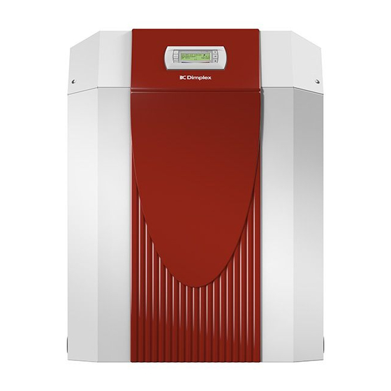
SI 10MER
Sole/Wasser-
Wärmepumpe für
Innenaufstellung
Bestell-Nr. / Order no. / N
Brine-to-Water
Heat Pump for
Indoor Installation
o
de commande : 452232.66.38
Montage- und
Gebrauchsanweisung
Installation and
Operating Instructions
Instructions d'installation
et d'utilisation
Pompe à chaleur
eau glycolée-eau
pour installation
intérieure
FD 9408
Kapitel
Inhaltsverzeichnis

Verwandte Anleitungen für Dimplex SI 10MER


Inhaltszusammenfassung für Dimplex SI 10MER
- Seite 1 SI 10MER Montage- und Gebrauchsanweisung Installation and Operating Instructions Instructions d’installation et d’utilisation Sole/Wasser- Brine-to-Water Pompe à chaleur Wärmepumpe für Heat Pump for eau glycolée-eau Innenaufstellung Indoor Installation pour installation intérieure Bestell-Nr. / Order no. / N de commande : 452232.66.38...
-
Seite 3: Inhaltsverzeichnis
SI 10MER Inhaltsverzeichnis Bitte sofort lesen ........................DE-2 1.1 Wichtige Hinweise ..........................DE-2 1.2 Bestimmungsgemäßer Gebrauch......................DE-2 1.3 Gesetzliche Vorschriften und Richtlinien ..................... DE-2 1.4 Energiesparende Handhabung der Wärmepumpe ................DE-2 Verwendungszweck der Wärmepumpe ..................DE-3 2.1 Anwendungsbereich ..........................DE-3 2.2 Arbeitsweise ............................ -
Seite 4: Bitte Sofort Lesen
SI 10MER Bitte sofort lesen 1.3 Gesetzliche Vorschriften und Richtlinien 1.1 Wichtige Hinweise Diese Wärmepumpe ist gemäß Artikel 1, Abschnitt 2 k) der EG- Richtlinie 2006/42/EC (Maschinenrichtlinie) für den Gebrauch im ACHTUNG! häuslichen Umfeld bestimmt und unterliegt damit den Anforde- Für den Betrieb und die Wartung einer Wärmepumpe sind die rechtlichen... -
Seite 5: Verwendungszweck Der Wärmepumpe
SI 10MER Verwendungszweck der Grundgerät Wärmepumpe Das Grundgerät besteht aus einer anschlussfertigen Wärme- pumpe für Innenaufstellung mit Blechgehäuse, Schaltkasten und integriertem Wärmepumpenmanager. Der Kältekreis ist „herme- 2.1 Anwendungsbereich tisch geschlossen“ und enthält das vom Kyoto-Protokoll erfasste fluorierte Kältemittel R410A mit einem GWP-Wert von 1975. Es Die Sole/Wasser-Wärmepumpe ist ausschließlich für die Erwär-... -
Seite 6: Zubehör
SI 10MER Zubehör 4.1 Soleverteiler Der Soleverteiler vereinigt die Kollektorschleifen der Wärmequel- lenanlage zu einer Hauptleitung, welche an die Wärmepumpe angeschlossen wird. Mittels der integrierten Kugelhähne können zum Entlüften einzelne Solekreise abgesperrt werden. Abb. 4.1: Raumklimastation 4.5 Wärmemengenzähler WMZ 4.5.1 Allgemeine Beschreibung Der Wärmemengenzähler (WMZ 25/32) dient dazu, die angege-... -
Seite 7: Transport
SI 10MER Transport Aufstellung Zum Transport auf ebenem Untergrund eignet sich ein Hubwa- 6.1 Allgemeine Hinweise gen. Muss die Wärmepumpe auf unebenem Untergrund oder über Treppen befördert werden, kann dies mit Tragriemen ge- Die Sole/Wasser-Wärmepumpe muss in einem frostfreien und schehen. -
Seite 8: Montage
SI 10MER Montage Sofern Wärmepumpenmanager und Heizungsumwälzpumpen betriebsbereit sind, arbeitet die Frostschutzfunktion des Wärme- pumpenmanagers. Bei Außerbetriebnahme der Wärmepumpe 7.1 Allgemein oder Stromausfall ist die Anlage zu entleeren. Bei Wärmepum- penanlagen, an denen ein Stromausfall nicht erkannt werden An der Wärmepumpe sind folgende Anschlüsse herzustellen: kann (Ferienhaus), ist der Heizungskreis mit seinem geeigneten ... -
Seite 9: Temperaturfühler
SI 10MER 7.4 Temperaturfühler 7.4.2 Montage des Außentemperaturfühlers Folgende Temperaturfühler sind bereits eingebaut bzw. müssen zusätzlich montiert werden: Der Temperaturfühler muss so angebracht werden, dass sämtli- che Witterungseinflüsse erfasst werden und der Messwert nicht Außentemperatur (R1) beigelegt (NTC-2) verfälscht wird. -
Seite 10: Elektrischer Anschluss
SI 10MER 7.5 Elektrischer Anschluss Das Schütz (K21) für die Flanschheizung (E9) im Warmwasserspeicher entsprechend Heizkörperleistung auszulegen und bauseits beizustellen. 7.5.1 Allgemein Die Ansteuerung (230 V AC) erfolgt aus dem WPM über die Klemmen X2/N und N1-J16/NO 10. Sämtliche elektrische Anschlussarbeiten dürfen nur von einer Elektrofachkraft oder einer Fachkraft für festgelegte Tätigkeiten... -
Seite 11: Inbetriebnahme
SI 10MER Inbetriebnahme 8.3 Vorgehensweise bei Inbetriebnahme 8.1 Allgemeine Hinweise Die Inbetriebnahme der Wärmepumpe erfolgt über den Wärme- pumpenmanager. Um eine ordnungsgemäße Inbetriebnahme zu gewährleisten, sollte diese von einem vom Werk autorisierten Kundendienst ACHTUNG! durchgeführt werden. Unter bestimmten Bedingungen ist damit Die Inbetriebnahme der Wärmepumpe muss gemäß... -
Seite 12: Pflege / Reinigung
SI 10MER Pflege / Reinigung 10 Störungen / Fehlersuche Diese Wärmepumpe ist ein Qualitätsprodukt und sollte störungs- 9.1 Pflege frei arbeiten. Tritt dennoch eine Störung auf, wird dies im Display des Wärmepumpenamanagers angezeigt. Schlagen Sie dazu Um Betriebsstörungen durch Schmutzablagerungen in den Wär- auf der Seite Störungen und Fehlersuche in der Gebrauchsan-... -
Seite 13: Geräteinformation
SI 10MER 12 Geräteinformation Typ- und Verkaufsbezeichnung SI 10MER Bauform Ausführung Reversibel Schutzart nach EN 60 529 IP 21 Aufstellungsort Innen Leistungsangaben Temperatur-Betriebseinsatzgrenzen: +20 bis +62 ±2 Heizwasser-Vorlauf °C Kühlen, Vorlauf °C +7 bis +20 Sole (Wärmequelle, Heizen) °C bis +25 Sole (Wärmesenke, Kühlen) - Seite 14 SI 10MER Entspricht den europäischen Sicherheitsbestimmungen Sonstige Ausführungsmerkmale Wasser im Gerät gegen Einfrieren geschützt Leistungsstufen Regler intern / extern intern max. Betriebsüberdruck (Wärmequelle/Wärmesenke) 1. Diese Angaben charakterisieren die Größe und Leistungsfähigkeit der Anlage nach EN 14511. Für wirtschaftliche und energetische Betrachtungen sind Bivalenzpunkt und Rege- lung zu berücksichtigen.
-
Seite 15: Garantieurkunde
Die aktuellen Inbetriebnahmepauschalen und der in der Inbetrieb- land oder Österreich erbracht werden können. nahmepauschale enthaltene Leistungsumfang sind im Internet unter: www.dimplex.de/garantieverlaengerung hinterlegt. Hier ist ebenfalls Die Behebung der von uns als garantiepflichtig anerkannter Mängel eine Online-Beauftragung integriert. geschieht dadurch, dass die mangelhaften Teile unentgeltlich nach... - Seite 16 SI 10MER DE-14 452232.66.38 · FD 9408 www.dimplex.de...
- Seite 49 SI 10MER 3.3 Last / Load / Charge www.dimplex.de 452232.66.38 · FD 9408 A-IX...
- Seite 51 SI 10MER 3.5 Anschlussplan Kühlregler / Terminal diagram for cooling controller / Schéma de branchement du régulateur de refroidissement www.dimplex.de 452232.66.38 · FD 9408 A-XI...
- Seite 52 SI 10MER 3.6 Legende / Legend / Légende Brücke EVU-Sperre, muss eingelegt werden, Utility block (EVU) bridge must be inserted if no Pont de blocage de la société d'électricité, à insérer wenn kein EVU-Sperrschütz vorhanden ist utility blocking contactor is present en absence de contacteur de blocage de la société...
- Seite 53 SI 10MER Vorlauffühler Heizkreis Flow sensor for heating circuit Sonde aller circuit de chauffage R13* Fühler regenerativ, Raumfühler, Renewable sensor, room sensor, Sonde mode régénératif, sonde d'ambiance, sonde Fühler 3. Heizkreis sensor for heating circuit 3 3ème circuit de chauffage R20* Schwimmbadfühler...
-
Seite 54: Hydraulisches Einbindungsschema / Hydraulic Integration Diagram / Schéma D'intégration Hydraulique
SI 10MER 4 Hydraulisches Einbindungsschema / Hydraulic integration diagram / Schéma d’intégration hydraulique 4.1 Monoenergetische Anlage mit dynamischer Kühlung und Warmwasserbereitung / Mono energy system with dynamic cooling and domestic hot water preparation /Installation mono-énergétique avec rafaîchissemant dynamique et production d'eau chaude sanitaire A-XIV 452232.66.38 ·... - Seite 55 SI 10MER 4.2 Legende / Legend / Légende Rückschlagventil Check valve Clapet anti-retour Absperrventil Shutoff valve Robinet d’arrêt Schmutzfänger Dirt trap Filtre Umwälzpumpe Circulating pump Circulateur Ausdehnungsgefäß Expansion vessel Vase d´expansion Vanne commandée par Raumtemperaturgesteuertes Ventil Room temperature-controlled valve température ambiante Absperrventil mit Rückschlagventil...
-
Seite 56: Konformitätserklärung / Declaration Of Conformity / Déclaration De Conformité
5 Konformitätserklärung / Declaration of Conformity / Déclaration de conformité EG - Konformitätserklärung EC Declaration of Conformity Déclaration de conformité CE Der Unterzeichnete Glen Dimplex Deutschland GmbH The undersigned Geschäftsbereich Dimplex L’entreprise soussignée, Am Goldenen Feld 18 D - 95326 Kulmbach bestätigt hiermit, dass das (die) - Seite 57 SI 10MER www.dimplex.de 452232.66.38 · FD 9408 A-XVII...
- Seite 58 SI 10MER A-XVIII 452232.66.38 · FD 9408 www.dimplex.de...
- Seite 59 SI 10MER www.dimplex.de 452232.66.38 · FD 9408 A-XIX...
- Seite 60 Glen Dimplex Deutschland GmbH Irrtümer und Änderungen vorbehalten. Geschäftsbereich Dimplex Subject to alterations and errors. Am Goldenen Feld 18 Sous réserve d’erreurs et modifications. D-95326 Kulmbach +49 (0) 9221 709 565 www.dimplex.de...