R&G LP0290BK Montageanleitung
Verfügbare Sprachen
Verfügbare Sprachen
Page 1 of 21
LP0290BK
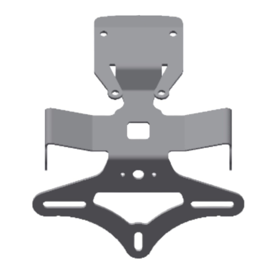
FITTING INSTRUCTIONS FOR LP0290BK LICENCE PLATE BRACKET
FOR KAWASAKI Z900 2020-
FOR ORIGINAL AND AFTERMARKET M8 INDICATORS
T
.
HIS KIT CONTAINS THE ITEMS PICTURED AND LABELLED OVER PAGE
S
.
OME PARTS MAY BE SHOWN FOR CLARITY OF INSTRUCTIONS ONLY
D
.
O NOT PROCEED UNTIL YOU ARE SURE ALL PARTS ARE PRESENT
P
.
LEASE READ ALL INSTRUCTIONS BEFORE PROCEEDING
IF IN ANY DOUBT WHEN FITTING OUR PRODUCTS, CONSULT ONE OF OUR DEALERS
OR HAVE FITTED BY A QUALIFIED TECHNICIAN.
P
LEASE NOTE THAT THE WAY THE KIT IS PACKED DOES NOT NECESSARILY REPRESENT THE WAY OF
.
MOUNTING TO THE BIKE
I
,
N THE EVENT OF RUBBER WASHERS BEING USED TO HOLD COMPONENTS ONTO BOLTS
.
THESE RUBBER WASHERS CAN BE THROWN AWAY
DIGITAL COPIES OF THESE INSTRUCTIONS ARE AVAILABLE FROM:
WWW.RG-RACING.COM
R&G
Unit 1, Shelley's Lane, East Worldham, Alton, Hampshire, GU34 3AQ
Tel: +44 (0)1420 89007 Fax: +44 (0)1420 87301
www.rg-racing.com
Email:
info@rg-racing.com
Inhaltsverzeichnis

Verwandte Anleitungen für R&G LP0290BK


Inhaltszusammenfassung für R&G LP0290BK
- Seite 18 Page 18 of 21 LP0290BK SIE BENÖTIGEN FOLGENDES WERKZEUG ALLGEM. ANZUGSDREHMOMENT • M4 SCHRAUBE = 8Nm Satz Inbusschlüssel inkl. 4 & 5mm A/F M5 SCHRAUBE = • 6 und 8mm Schraubenschlüssel oder Steckschlüssel M6 SCHRAUBE = • M8 SCHRAUBE = 20Nm...
- Seite 19 Page 19 of 21 LP0290BK Zusammenbau – Zeichnung 1 MONTAGEANLEITUNG • Um den R&G Kennzeichenhalter montieren zu können, entfernen Sie zuerst den Soziussitz (der Schlüssel wird hierfür benötigt). • Die Verriegelung des Fahrersitzes in die Richtung schieben wie in Abbildung 2 abgebildet und den Fahrersitz entfernen.
- Seite 20 Page 20 of 21 LP0290BK Wenn Sie die Originalblinker verwenden • Entfernen Sie Mutter an der Halterung für den Rückstrahler, die in Abbildung 12 markiert ist. • Entfernen Sie die zwei Schrauben, die in den Abbildungen 13 und 14 gekennzeichnet sind, um den Halter in zwei Teilen trennen zu können wie in Abbildung 15 abgebildet.
- Seite 21 Page 21 of 21 LP0290BK • Führen Sie die Kabel der neuen R&G Kennzeichenbeleuchtung (Artikel 10) durch die mittlere Öffnung im neuen Kennzeichenhalter (Artikel 1) wie in den Abbildungen 25 and 26 abgebildet. • Mit den Unterlegscheiben und Mutter vom Kit befestigen wie in Abbildung 26 abgebildet.