LD Systems IPA 412 T Bedienungsanleitung
Installation dsp power amplifier

Verwandte Anleitungen für LD Systems IPA 412 T


Inhaltszusammenfassung für LD Systems IPA 412 T
-
Seite 2: Inhaltsverzeichnis
CONTENTS / INHALTSVERZEICHNIS ENGLISH DEUTSCH SAFETY INFORMATION SICHERHEITSHINWEISE INTRODUCTION EINFÜHRUNG FEATURES EIGENSCHAFTEN PACKAGING CONTENT LIEFERUMFANG CONNECTIONS, CONTROLS AND DISPLAY ELEMENTS ANSCHLÜSSE, BEDIEN- UND ANZEIGEELEMENTE ASSIGNMENT OF THE TERMINAL BLOCK CONNECTIONS AND SETUP EXAMPLES 11 BELEGUNG DER KLEMMBLOCKANSCHLÜSSE UND SETUP-BEISPIELE TECHNICAL DATA TECHNISCHE DATEN MANUFACTURER´S DECLARATIONS HERSTELLERERKLÄRUNGEN... -
Seite 15: Deutsch
Dieses Gerät wurde unter hohen Qualitätsanforderungen entwickelt und gefertigt, um viele Jahre einen reibungslosen Betrieb zu gewährleisten. Dafür steht LD Systems mit seinem Namen und der langjährigen Erfahrung als Hersteller hochwertiger Audioprodukte. Bitte lesen Sie diese Bedie- nungsanleitung sorgfältig, damit Sie Ihr neues Produkt von LD Systems schnell optimal einsetzen können. -
Seite 16: Einführung
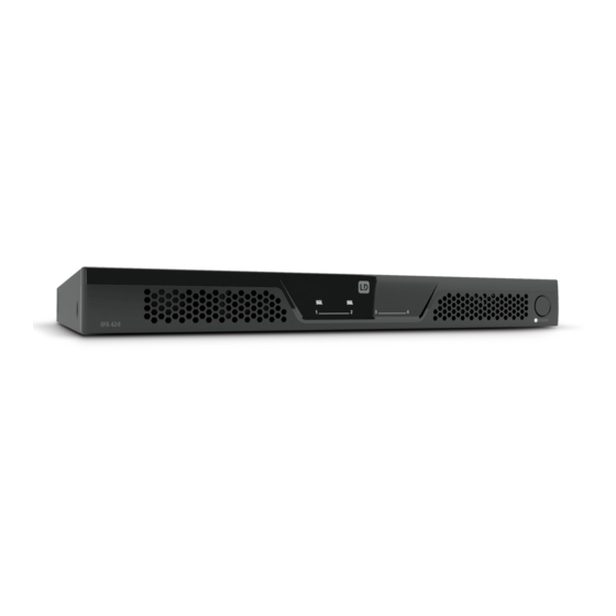
EINFÜHRUNG IPA 424 T und IPA 412 T sind DSP-basierte 4-Kanal-Installationsverstärker im 19-Zoll-Rack-Format, die speziell für professionelle Audioinstallationen entwickelt wurden. Sie verfügen über integrierte Transformatoren pro Kanal und bieten Anschlüsse für 100 V / 70 V und Low-Z-Systeme bis zu 4 Ohm. -
Seite 17: Eigenschaften
EIGENSCHAFTEN • Professionelle 4-Kanal DSP-basierte Class D Endstufe • 4 x 240W (IPA 424 T) bzw. 4 x 120W (IPA 412 T) @ 4 Ohm / 100V / 70V • 4 symmetrische Line-Eingänge und 4 Lautsprecherausgänge mit Klemmenblockanschlüssen • Benutzerfreundliches Frontpanel-Design mit Signal-, Limit-, Protection-, Mute- und Bridge-Modus-Anzeigen pro Kanal •... -
Seite 18: Eingangssektion
REMOTE IN / OUT RJ45-Anschlüsse für LD Systems REMOTE-Bus-Zubehör. Das Zubehör wird in Reihe am REMOTE IN angeschlossen. Ein RJ45-Busabschlussstecker befin- det sich im Lieferumfang, dieser sollte standardmäßig an REMOTE OUT angeschlossen sein und unter normalen Umständen nicht von dieser Buchse entfernt werden. -
Seite 19: Ausgangssektion
Die Micro-USB-Schnittstelle ist reserviert für Servicezwecke. Versuchen Sie nicht, eine Verbindung zu einem externen Gerät herzustellen. AUSGANGSSEKTION LAUTSPRECHERAUSGÄNGE CH1 - CH4 Vier 4-polige Klemmblockanschlüsse CH1 bis CH4 für den Anschluss von Lautsprechern in der vorgewählten Betriebsart (100V, 70V, 4 Ohm). Entneh- men Sie die des Lautsprechersystems entsprechende Pinbelegung dem Aufdruck zwischen den Klemmblockanschlüssen. -
Seite 20: Beschreibung
Schalten Sie während der Phase unter Punkt F den Verstärker nicht aus und nehmen keine Einstellungsänderungen vor! DIP-SCHALTER 3 REM MODE (REMOTE MODE) Der DIP-Schalter 3 REM MODE ist für die Integration von zukünftigem LD Systems Remote-Bus-Zubehör reserviert. Detaillierte Informationen dazu entnehmen Sie bitte der Anleitung des zusätzlichen Remote-Bus-Zubehörs. Derzeit ist der DIP-Schalter ohne Funktion. - Seite 21 FAULT 1-2 UND FAULT 3-4 Fehlerrelais zum Übermitteln des Gerätebetriebszustands an ein angeschlossenes Überwachungs- bzw. Redundanzsystem. FAULT 1-2: Wenn das Gerät ausgeschaltet ist, sich im Wartezustand befindet (Standby), oder die Protect-Schaltung eines der beiden Verstärkerkanäle 1 und 2 aktiv ist, wird der Kontakt NC zu C geschlossen und der Kontakt NO zu C geöffnet. Im Normalbetrieb ist der Kontakt NC geöffnet und der Kontakt NO geschlossen.
- Seite 22 ANZEIGEFELDER FÜR DEN KANALSTATUS KANAL 1 - 4 PROT (Protect) - Das Anzeigefeld Protect zeigt unterschiedliche Betriebszustände an. Informationen dazu entnehmen Sie bitte untenstehender Tabelle. LED Status Beschreibung Mögliche Ursachen Protect aus Das Verstärker-Modul des entsprechenden Kanals arbeitet normal. Protect blinkt langsam Das Gerät hat eine hohe Temperatur am Verdeckte Lüftungsschlitze, verstaubte Lüfter, (ca.
-
Seite 23: Belegung Der Klemmblockanschlüsse Und Setup-Beispiele
BELEGUNG DER KLEMMBLOCKANSCHLÜSSE UND SETUP-BEISPIELE... -
Seite 24: Technische Daten
TECHNISCHE DATEN Artikelbezeichnung: LDIPA424T LDIPA412T Produkttyp: Leistungsverstärker für Festinstallationen Allgemeine Daten Audiokanäle: Ausgangsschaltung: Class D Stromversorgung: Weitbereichs-Schaltnetzteil mit PFC (Leistungsfaktorkorrekturfilter) Netzanschluss: 3-Pol-Kaltgerätebuchse (IEC) Auto-Standby-Modus: Ja. Umschaltbar (Ein-Aus) Zeit bis zum Auto-Standby: 20 Min. ohne Audioeingangssignal DSP: Remote-Bus: Anzeigeelemente: Rückseite: 4 x Eingangssignal-Clip-LEDs, Remote-Sperr-LED (rot). Vorderseite: „PROT“, „LIMIT“, „SIG“, „BRIDGE“... - Seite 25 Artikelbezeichnung: LDIPA424T LDIPA412T Tiefe: 425 mm (mit Klemmblockanschlüssen) Gewicht: 11,36 kg 8,7 kg Rack-Abstand zum nächsten 1 HE Gerät (Höhe): Rack-Tiefe (erforderlich): 500 mm Ausgangsspezifikationen des Verstärkers, alle Ausgänge angesteuert und belastet Ausgangsleistung (1 kHz bei 4 x 240 W (1,5 Sekunden Sinus-Burst) 4 x 120 W (1,5 Sekunden Sinus-Burst) 4 Ohm): Ausgangsleistung (1 kHz bei...
-
Seite 26: Herstellererklärungen
Artikelbezeichnung: LDIPA424T LDIPA412T Auflösung AD/DA-Wandler: 24 Bit PCM1865 (AD), 24 Bit PCM1690 (DA) Abtastrate AD/DA-Wandler: 48 kHz Remote-Bus-Spezifikationen, gemessen zwischen REM In und SPK Out Eingangsempfindlichkeit, 20 dBu nominal: Eingangsübersteuerung, 20 dBu nominal: Klirrfaktor (THD+N): <0,006 % (Low-Z SPK OUT, +18 dBu, 20 Hz – 20 kHz) Frequenzgang: 20 Hz –... - Seite 28 ld-systems.com Adam Hall GmbH | Adam-Hall-Str. 1 | 61267 Neu-Anspach | Germany Phone: +49 6081 9419-0 | adamhall.com REV: 02...