Herunterladen Inhalt Inhalt Diese Seite drucken
Garbin 25GE VAP Installationsanleitungen

Garbin 25GE VAP Installationsanleitungen

Lektrische umluftöfen
Inhaltsverzeichnis

Werbung

Verfügbare Sprachen
  • DE

Verfügbare Sprachen

  • DEUTSCH, seite 80
manuale d'istruzione
operating instructions
notice d'entretien
installationsanleitungen
manual de instrucciones
REV03-FE004-01/2011
25GE VAP - 25GL VAP - 45GE VAP
45GL VAP - 46PE VAP - 46PL VAP
61GE VAP - 61GL VAP - 64PE VAP
64PL VAP - 101GE VAP - 101GL VAP
104PE VAP - 104PL VAP
FORNI ELETTRICI VENTILATI
ELECTRIC VENTILATED OVENS
FOURS ÉLECTRIQUES VENTILES
ELEKTRISCHE UMLUFTÖFEN
HORNOS ELÉCTRICOS VENTILADOS
IT
GB
FR
DE
ES

Werbung

Inhaltsverzeichnis
loading

Inhaltszusammenfassung für Garbin 25GE VAP

  • Seite 1 REV03-FE004-01/2011 25GE VAP - 25GL VAP - 45GE VAP 45GL VAP - 46PE VAP - 46PL VAP 61GE VAP - 61GL VAP - 64PE VAP 64PL VAP - 101GE VAP - 101GL VAP 104PE VAP - 104PL VAP...
  • Seite 3: Inhaltsverzeichnis

    3.2.1 - Pannello di controllo digitale ........................13 3.2.1a - Modelli 25GE VAP / 45GE VAP / 46PE VAP / 61GE VAP / 64PE VAP / 101GE VAP / 104PE VAP ..... 13-19 3.3.1 - Pannelli comandi forni con encoder ......................20 3.3.1a - Modelli 25GL VAP / 45GL VAP / 46PL VAP / 61GL VAP / 64PL VAP / 101GL VAP / 104PL VAP ....
  • Seite 4 3.1 - Einleitende Hinweise ........................... 88 3.2.1 - Digitales Steuerpaneel ..........................88 3.2.1a - Modelle 25GE VAP / 45GE VAP / 46PE VAP / 61GE VAP / 64PE VAP / 101GE VAP / 104PE VAP .... 88-94 3.3.1 - BefehlSpaneel Öfen mit ENCODER ......................95 3.3.1a - Modelle 25GL VAP / 45GL VAP / 46PL VAP / 61GL VAP / 64PL VAP / 101GL VAP / 104PL VAP ....
  • Seite 5: Parte Prima

    PARTE PRIMA 1.1 - INTRODUZIONE Nel ringraziare per la fiducia accordataci nell’acquisto di un nostro prodotto, raccomandiamo, prima di mettere in funzione i forni, di leggere attentamente questo manuale. Questa pubblicazione contiene tutte le informazioni necessarie per l’uso corretto e la manutenzione del forno.
  • Seite 6 • Per questo motivo Vi raccomandiamo di rivolgerVi sempre al Concessionario che ha effettuato la ° vendita, specificando l’inconveniente, il modello e n matricola del forno in Vostro possesso. • In caso di riparazione e/o sostituzione di componenti, di manutenzione straordinaria, di guasto o di funzionamento anomalo, rivolgersi solo a personale autorizzato dalla Ditta produttrice e dotato dei ne- cessari requisiti professionali.
  • Seite 7: Caratteristiche Tecniche E Targhetta Dati

    1.4 - Caratteristiche tecniche e targhetta dati Modello 25GE / 25GL VAP 45GE / 45GL VAP 46PE / 46PL VAP Potenza elettrica 3300 W 7000 W 7000 W Alimentazione 230V~; 50/60 Hz 400V~ 3N; 50/60 Hz 400V~ 3N; 50/60 Hz Connessione elettrica tipo “X”...
  • Seite 8 1.4.1 - Caratteristiche tecniche e targhetta dati Modello 61GE / 61GL VAP 64PE / 64PL VAP Potenza elettrica 9400 W 9400 W Alimentazione 400V~ (3N); 50/60 Hz 400V~ (3N); 50/60 Hz Connessione elettrica tipo “X” tipo “X” Peso 70 kg 70 kg Dimensioni (mm) 965 x 830 x 770...
  • Seite 9 1.5 - Movimentazione, trasporto e scarico • L’imballo del forno è realizzato dall’azienda conformemente agli accordi siglati, di volta in volta, o co- munque in funzione del Paese di destinazione, o del mezzo di trasporto utilizzato. • Dopo l’installazione, l’imballo può essere riutilizzato od avviato allo smaltimento nel rispetto delle norme vigenti nel Paese dell’acquirente.
  • Seite 10: Istruzioni Per L'installazione E La Manutenzione

    PARTE SECONDA 2.0 - Istruzioni per l’installazione e la manutenzione 2.1 - Luogo d’installazione e posizionamento AVVERTENZA L’installazione e la manutenzione ordinaria o straordinaria del forno devono essere eseguite esclusivamente da installatori autorizzati o comunque da personale qualificato ed in confor- mità...
  • Seite 11: Collegamento Elettrico

    Prima di avviare il forno, togliere la pellicola protettiva dalle pareti esterne; gli eventuali resi- dui di collante che possono rimanere sulle superfici vanno rimossi con idoneo solvente. • I forni possono essere installati su banco fisso (piedini) o su apposito cavalletto d’appoggio fornito dal costruttore come accessorio.
  • Seite 12: Messa A Terra

    2.3 - Messa a terra • Il forno deve essere collegato ad un efficace impianto di terra. • A tale scopo, la morsettiera di alimentazione è accessibile sulla parte posteriore del forno. • Il filo giallo/verde del cavo d’alimentazione, deve essere fissato al morsetto contrassegnato con il sim- bolo di terra (vedi fig.
  • Seite 13: Messa In Funzione

    2.6 - Messa in funzione Controllare: • La corretta installazione del forno, la sua stabilità e la perfetta messa a bolla. • La corretta realizzazione dell’allacciamento elettrico, conformità del cavo elettrico, presenza ed efficacia dell’interruttore onnipolare e dell’impianto elettrico. • L’efficienza dell’impianto di alimentazione dell’acqua e di scarico dei vapori (assenza di perdite). •...
  • Seite 14 Ricordarsi di ripristinare le guarnizioni, i sigillanti e le guaine inserite, prima di terminare il lavoro. 2.9.1 - Sostituzione del termostato di sicurezza • Il bulbo del termostato si trova a destra della cella di cottura, dietro il supporto teglie: 1) Aprire il fianco destro del forno;...
  • Seite 15 2.9.3 - Guarnizione della porta • La guarnizione è inserita a pressione, quindi deve essere estratta tirandola e inserita nuovamente a pressione. Tale operazione deve essere eseguita a mano per non danneggiare la guarnizione. 2.9.4 - Ventola e motore fig. 10 •...
  • Seite 16: Avvertenze Preliminari

    PARTE TERZA ISTRUZIONI PER L’USO 3.1 - Avvertenze preliminari • L’apparecchiatura è destinata ad un uso professionale e deve essere utilizzata da personale addestrato. • Il forno deve essere adibito esclusivamente alla cottura di cibi, ogni altro impiego è da ritenersi improprio. É...
  • Seite 17: Pannello Di Controllo Digitale

    3.2.1 - PANNELLO DI CONTROLLO DIGITALE 25GE VAP / 45GE VAP / 46PE VAP / 61GE VAP / 64PE VAP / 101GE VAP / 104PEVAP Interruttore generale Display temperatura LED temperatura Tasto temperatura Display tempo LED sonda al cuore Sonda al cuore Tasto tempo Display umidità...
  • Seite 18 3.2.1a - MODELLI 25GE VAP / 45GE VAP / 46PE VAP / 61GE VAP / 64PE VAP / 101GE VAP / 104PEVAP ON/OFF ACCENSIONE E SPEGNIMENTO Quando viene collegata la tensione, la scheda per alcuni se- condi mostra la scritta versione del software. Quindi il forno si porta in stato di OFF e si accende sul display tempo il led e resta in attesa.
  • Seite 19 3.2.1b - MODELLI 25GE VAP / 45GE VAP / 46PE VAP / 61GE VAP / 64PE VAP / 101GE VAP / 104PEVAP TASTO START/STOP Premendo START/STOP: Parte il ciclo di cottura, si attiva la luce interna, (la partenza non avviene mai né durante il settaggio né alla fine del settaggio senza il comando esplicito START).
  • Seite 20: Tempo Di Cottura

    3.2.1c - MODELLI 25GE VAP / 45GE VAP / 46PE VAP / 61GE VAP / 64PE VAP / 101GE VAP / 104PEVAP TASTO TEMPERATURA Impostabile da 0 °C a 270 °C Valore di default per temperatura: 100 °C Durante un ciclo di cottura si possono variare i dati impostati ripremendo il tasto temperatura a questo punto il display lam- peggia e si ripete l‘operazione inserimento dati.
  • Seite 21 3.2.1d - MODELLI 25GE VAP / 45GE VAP / 46PE VAP / 61GE VAP / 64PE VAP / 101GE VAP / 104PEVAP TASTO UMIDITÀ Impostabile da 0 a 99 Default 00 Esempio tempi: 100% uguale 60 sec on 50% uguale 30 sec on e 30 sec off 10% 6 sec on 54 sec off Il display lampeggia valore di default 0, con i tasti più...
  • Seite 22 3.2.1e - MODELLI 25GE VAP / 45GE VAP / 46PE VAP / 61GE VAP / 64PE VAP / 101GE VAP / 104PEVAP PROGRAMMI (FASE) Il forno deve trovarsi nella posizione di scheda accesa con il display temperatura che lampeggia (fase iniziale) Premendo il tasto P si entra in programmazione ed il relativo display lam- peggia in attesa di inserimento dati.
  • Seite 23 3.2.1f - MODELLI 25GE VAP / 45GE VAP / 46PE VAP / 61GE VAP / 64PE VAP / 101GE VAP / 104PEVAP COMANDI PARTICOLARI TASTO UMIDIFICAZIONE MANUALE Funzione solo con un ciclo attivo. Premendo il tasto viene visualizzato sul display umidità il tem- po in secondi per un massimo di 10 secondi, si attiva il relativo relè, una volta rilasciato il display ritorna a visualizzare il dato...
  • Seite 24: Pannelli Comandi Forni Con Encoder

    3.3.1 - PANNELLO COMANDI FORNI CON ENCODER 25GL VAP / 45GL VAP / 46PL VAP / 61GL VAP / 64PL VAP / 101GL VAP / 104PL VAP Display temperatura Manopola temperatura Display tempo Manopola tempo Display umidità Manopola umidità Display sonda al cuore* Manopola sonda al cuore* Interruttore generale Tasto START/STOP...
  • Seite 25 3.3.1a - MODELLI 25GL VAP / 45GL VAP / 46PL VAP / 61GL VAP / 64PL VAP / 101GL VAP / 104PL VAP ON/OFF ACCENSIONE E SPEGNIMENTO Quando viene collegata la tensione, la scheda per alcuni se- condi mostra la scritta versione del software. Quindi il forno si porta in stato di OFF e si accende sul display tempo il led e resta in attesa.
  • Seite 26 3.3.1b - MODELLI 25GL VAP / 45GL VAP / 46PL VAP / 61GL VAP / 64PL VAP / 101GL VAP / 104PL VAP TASTO START/STOP Premendo START/STOP: Parte il ciclo di cottura, si attiva la luce interna. Il display temperatura passa dalla visualizzazione set point im- postato a set temperatura camera e il relativo led si accende fino al raggiungimento del set point impostato, si spegne oltre il set point impostato e si riaccende al di sotto del set point impo-...
  • Seite 27 3.3.1c - MODELLI 25GL VAP / 45GL VAP / 46PL VAP / 61GL VAP / 64PL VAP / 101GL VAP / 104PL VAP MANOPOLA TEMPERATURA Impostabile da 0 °C a 270 °C Valore di default per temperatura: 100 °C Durante un ciclo di cottura si possono variare i dati impostati ruotando la manopola temperatura a questo punto il display lampeggia e si ripete l‘operazione inserimento dati.
  • Seite 28 3.3.1d - MODELLI 25GL VAP / 45GL VAP / 46PL VAP / 61GL VAP / 64PL VAP / 101GL VAP / 104PL VAP MANOPOLA UMIDITÀ Impostabile da 0 a 99 Default 00 Esempio tempi: 100% uguale 60 sec on 50% uguale 30 sec on e 30 sec off 10% 6 sec on 54 sec off Il display lampeggia valore di default 0, ruotando la manopola inserisco il dato.
  • Seite 29 3.4 - Operazioni dopo l’uso 1) Spegnere il forno. 2) Chiudere i rubinetti di alimentazione dell’acqua. Disinserire l’interruttore generale di alimentazione elet- trica. 3.5 - Pulizia e manutenzione ordinaria del forno • I forni devono essere puliti quotidianamente per garantire la migliore funzionalità, igiene e rendimento. In caso di guasto, non tentare di risolvere il problema ma rivolgersi all’assistenza tecnica che provvede- rà...
  • Seite 30: First Part

    FIRST PART 1.1 - INTRODUCTION Congratulations on your purchase of this product. We thank you for your patronage whilst reminding you to read this manual carefully before operating the ovens. This publication contains all the information you will need to use and service the ovens properly. The purpose of this manual is to allow the user, and above all the direct user, to take every step and to arrange all the means, human resources and materials necessary for safe and lasting use of the ovens.
  • Seite 31 • Consequently, you are strongly advised to always contact the Dealer who sold the appliance, specifying the problem, the model and serial number of the appliance you have. • Only contact personnel authorized by the Manufacturer, with the necessary professional qualifications, for repairs and replacement of parts, and non-routine maintenance, or if the appliance breaks down or malfunctions.
  • Seite 32: Technical Specifications And Rating Plate

    1.4 - Technical specifications and rating plate Model 25GE/25GL VAP 45GE/45GL VAP 46PE/46PL VAP Power 3300 W 7000 W 7000 W Power supply 230V~; 50/60 Hz 400V~ 3N; 50/60 Hz 400V~ 3N ; 50/60 Hz Electrical connection Type “X” Type “X” Type “X”...
  • Seite 33 1.4.1 - Technical specifications and rating plate Model 61GE/61GL VAP 64PE/64PL VAP Power 9400 W 9400 W Power supply 400V~ (3N); 50/60 Hz 400V~ (3N); 50/60 Hz Electrical connection Type “X” Type “X” Weight 70 kg 70 kg Dimensions (mm) 965 x 830 x 770 965 x 830 x 770 Capacity...
  • Seite 34 1.5 - Handling, transportation and unloading • The appliances’ packaging is produced by the company in accordance with the arrangements signed case by case or, nonetheless, depending on what country the appliance is being sent to, or on the means of transport used. •...
  • Seite 35: Installation Instructions And Maintenance

    SECOND PART 2.0 - Installation instructions and maintenance 2.1 - Installation site and positioning WARNING The oven’s installation, transformation and non-routine maintenance must be performed only by authorized installers or by the electricity company in conformity with the safety regulations in force.
  • Seite 36: Wiring

    Before starting the oven, remove the protective film from the external walls; remove any residuals of glue from the surfaces using a suitable solvent. • The oven can be installed on a fixed counter (with feet) or on a special support stand supplied by the Manufacturer as an accessory.
  • Seite 37 2.3 - Mains’ earth line • The appliance must be connected to the mains’ earth line. • For this purpose, the power terminal board is accessible on the back of the oven, and the yellow/green wire of the power cord must be fastened to the terminal marked (see pict.
  • Seite 38: Putting Into Operation

    2.6 - Putting into operation Check that: • The oven has been installed correctly, is stable and perfectly level. • The electrical connection has been made correctly, the electrical cable complies and the multiple pole switch and the electrical system are present and effective. •...
  • Seite 39 Remember to restore and put back the seals, sealants and sheathing inserted, before finishing the work. 2.9.1 - Replacing the safety thermostat • The thermostat bulb is located on the right of the cooking chamber, behind the baking-pan support: 1) Open the right-hand side of the oven; 2) Remove the bulb inside the oven chamber;...
  • Seite 40 2.9.3 - Door seal • The seal is pressed into place, therefore it must be pulled out and pressed back into place. This operation must be done by hand so as not to damage the seal. 2.9.4 - Fan and motor •...
  • Seite 41: Preliminary Warnings

    THIRD PART OPERATING INSTRUCTIONS 3.1 - Preliminary warnings • The appliance is designed for professional use and must be used by trained personnel. • The oven must be used for cooking food only. Any other use shall be considered improper. NEVER clean the inside of the oven or the door glass with jets of cold water when still at °...
  • Seite 42: Digital Control Panel

    3.2.1 - DIGITAL CONTROL PANEL 25GE VAP / 45GE VAP / 46PE VAP / 61GE VAP / 64PE VAP / 101GE VAP / 104PEVAP Main switch Temperature display Temperature LED Temperature button Time display Core probe LED Core probe Time button...
  • Seite 43 3.2.1a - MODELS 25GE VAP / 45GE VAP / 46PE VAP / 61GE VAP / 64PE VAP / 101GE VAP / 104PEVAP SWITCHING ON/OFF When power is connected, the panel shows the software version message for a few seconds. Then the oven switches itself OFF, the LED on the time display lights up and the oven remains in standby.
  • Seite 44 3.2.1b - MODELS 25GE VAP / 45GE VAP / 46PE VAP / 61GE VAP / 64PE VAP / 101GE VAP / 104PEVAP START/STOP BUTTON Pressing START/STOP: starts the cooking cycle. The internal light comes on, (the cycle never starts during or at the end of setting without the explicit START command).
  • Seite 45: Cooking Time

    3.2.1c - MODELS 25GE VAP / 45GE VAP / 46PE VAP / 61GE VAP / 64PE VAP / 101GE VAP / 104PEVAP TEMPERATURE BUTTON Can be set from 0 °C to 270 °C Default value for temperature: 100 °C During a cooking cycle, it is possible to vary the data set by pressing the temperature button again.
  • Seite 46 3.2.1d - MODELS 25GE VAP / 45GE VAP / 46PE VAP / 61GE VAP / 64PE VAP / 101GE VAP / 104PEVAP HUMIDITY BUTTON Can be set from 0 to 99 Default 00 Example of times: 100% = 60 sec. on 50% = 30 sec.
  • Seite 47 3.2.1e - MODELS 25GE VAP / 45GE VAP / 46PE VAP / 61GE VAP / 64PE VAP / 101GE VAP / 104PEVAP PROGRAMS (PHASE) The oven must have the panel on with the temperature display flashing (initial phase). Pressing the P button gives access to programming and the corresponding display flashes, waiting for data entry.
  • Seite 48: Special Controls

    3.2.1f - MODELS 25GE VAP / 45GE VAP / 46PE VAP / 61GE VAP / 64PE VAP / 101GE VAP / 104PEVAP SPECIAL CONTROLS MANUAL HUMIDIFICATION BUTTON Only operates with an active cycle. Pressing the button shows the time in seconds for a maximum of 10 seconds on the humidity display.
  • Seite 49: Oven Control Panel With Encoder

    3.3.1 - OVEN CONTROL PANEL WITH ENCODER 25GL VAP / 45GL VAP / 46PL VAP / 61GL VAP / 64PL VAP / 101GL VAP / 104PL VAP Temperature display Temperature knob Time display Time knob Humidity display Humidity knob Core probe display * Core probe knob* Main switch START/STOP button...
  • Seite 50: Switching On/Off

    3.3.1a - MODELS 25GL VAP / 45GL VAP / 46PL VAP / 61GL VAP / 64PL VAP / 101GL VAP / 104PL VAP SWITCHING ON/OFF When power is connected, the panel shows the software version message for a few seconds. Then the oven switches itself OFF, the LED on the time display lights up and the oven remains in standby.
  • Seite 51 3.3.1b - MODELS 25GL VAP / 45GL VAP / 46PL VAP / 61GL VAP / 64PL VAP / 101GL VAP / 104PL VAP START/STOP BUTTON Pressing START/STOP: starts the cooking cycle. The internal light comes on. The temperature display changes from showing the set point to showing the chamber temperature and the corresponding LED lights up until the set point is reached.
  • Seite 52 3.3.1c - MODELS 25GL VAP / 45GL VAP / 46PL VAP / 61GL VAP / 64PL VAP / 101GL VAP / 104PL VAP TEMPERATURE KNOB Can be set from 0 °C to 270 °C Default value for temperature: 100 °C During a cooking cycle, it is possible to vary the data set by turning the temperature knob.
  • Seite 53 3.3.1d - MODELS 25GL VAP / 45GL VAP / 46PL VAP / 61GL VAP / 64PL VAP / 101GL VAP / 104PL VAP HUMIDITY KNOB Can be set from 0 to 99 Default 00 Example of times: 100% = 60 sec. on 50% = 30 sec.
  • Seite 54: Cleaning The Fan And Heating System

    3.4 - Operations after use 1) Switches off the oven. 2) Turn off the water supply taps. Disconnect the main electrical power switch. 3.5 - Oven cleaning and routine maintenance • Ovens must be cleaned daily if high levels of performance, hygiene and efficiency are to be maintained. If you encounter a fault, do not attempt to solve the problem - contact the technical service centre instead, which will deal with the problem.
  • Seite 55: Première Partie

    PREMIÈRE PARTIE 1.1 - INTRODUCTION Nous vous remercions de la confiance que vous nous avez accordée en achetant un de nos produits. Avant d’utiliser les fours, il est vivement recommandé de lire avec attention le présent manuel. Il contient toutes les informations nécessaires à l’utilisation et à l’entretien des fours. Le but de ce manuel est de permettre à...
  • Seite 56 • L’installation ainsi que toute intervention de réparation ou de mise au point qui s’avéreraient nécessaires doivent être effectuées avec le plus grand soin et confiées à un personnel qualifié. Il est dans ce cas vivement recommandé de s’adresser au revendeur en mentionnant à cette occasion la nature de l’anomalie, le modèle et numéro de série de four.
  • Seite 57: Caractéristiques Techniques Et Plaques Des Données

    1.4 - Caractéristiques techniques et plaques des données Modèle 25GE/25GL VAP 45GE/45GL VAP 46PE/46PL VAP Puissance électrique 3300 W 7000 W 7000 W Alimentation 230V~; 50/60 Hz 400V~ 3N; 50/60 Hz 400V~ 3N; 50/60 Hz Connexion électrique Type “X” Type “X” Type “X”...
  • Seite 58 1.4.1 - Caractéristiques techniques et plaques des données Modèle 61GE/61GL VAP 64PE/64PL VAP Puissance électrique 9400 W 9400 W Alimentation 400V~ (3N); 50/60 Hz 400V~ (3N); 50/60 Hz Connexion électrique Type “X” Type “X” Poids 70 kg 70 kg Dimensions (mm) 965 x 830 x 770 965 x 830 x 770 Capacité...
  • Seite 59 1.5 - Transport, déplacement et déchargement • L’emballage des appareils est assuré par le fabricant conformément aux accords pris avec le client et dans tous les cas en fonction du pays de destination et/ou du moyen de transport utilisé. • Une fois l’installation effectuée, l’emballage peut être réutilisé ou éliminé dans le respect des normes en vigueur dans le pays de l’acheteur.
  • Seite 60: Lieu D'installation Et Positionnement

    DEUXIÈME PARTIE 2.0 - Instructions d’installation et d’entretien 2.1 - Lieu d’installation et positionnement RECOMMANDATION L’installation, la transformation et les opérations d’entretien exceptionnel du four doivent être confiées exclusivement aux installateurs agréés ou à la société assurant la fourniture d’énergie électrique conformément aux normes de sécurité...
  • Seite 61: Branchement Électrique

    Avant de mettre en marche le four, enlever le film de protection des parois extérieures; les éventuels résidus de colle qui peuvent rester sur les surfaces doivent être enlevés avec un solvant approprié. Les fours peuvent être installés sur un banc fixe (avec des pieds) ou sur un chevalet d’appui prévu à cet effet fourni par le constructeur comme accessoire.
  • Seite 62: Mise À Terre

    2.3 - Mise à terre • L’appareil doit être raccordé à la ligne de terre du secteur. • Pour cela, le bornier d'alimentation est accessible dans la partie postérieure du four; le fil jaune-vert du câble d’alimentation doit être fixé à la borne marquée du symbole (fig.
  • Seite 63: Mise En Service

    2.6 - Mise en service Contrôler: • S’assurer de la bonne installation du four, de sa stabilité et de sa parfaite horizontalité; • S'assurer que le branchement électrique soit correctement réalisé, de la conformité du câble électrique, de la présence et de l'efficacité de l'interrupteur unipolaire et de l'installation électrique. •...
  • Seite 64 Rappelez-vous de remplacer les joints, les mastics, et les gaines insérées, avant de terminer le travail. 2.9.1 - Remplacement du thermostat de sécurité • Le bulbe du thermostat se trouve à droite de la chambre de cuisson, derrière le support plaques: 1) Ouvrir le côté...
  • Seite 65 2.9.3 - Joints de la porte • Le joint est inséré sous pression, il doit donc être extrait en étant tiré et inséré de nouveau sous pression. Cette opération doit être exécuté à la main pour ne pas endommager le joint. 2.9.4 - Ventilateur et moteur fig.
  • Seite 66: Recommandations Préalables

    TROISIÈME PARTIE INSTRUCTIONS D’UTILISATION 3.1 - Recommandations préalables • L’appareil est exclusivement destiné à un usage professionnel et doit être utilisé par un personnelqualifié à cet effet. • Le four est exclusivement prévu pour la cuisson d’aliments; toute autre utilisation doit être considérée comme impropre.
  • Seite 67: Panneau De Commande Numerique

    3.2.1 - PANNEAU DE COMMANDE NUMÉRIQUE 25GE VAP / 45GE VAP / 46PE VAP / 61GE VAP / 64PE VAP / 101GE VAP / 104PEVAP Interrupteur général Écran température Voyant température Bouton température Écran temps Voyant sonde au cœur Sonde au cœur Bouton temps Écran humidité...
  • Seite 68 3.2.1a - MODÈLES 25GE VAP / 45GE VAP / 46PE VAP / 61GE VAP / 64PE VAP / 101GE VAP / 104PEVAP ON/OFF MARCHE ET ARRÊT Quand l'appareil est mis sous tension, la carte affiche pendant quelques secondes la version du logiciel. Puis le four se place en état de OFF, le voyant s'allume sur l'écran temps et reste en...
  • Seite 69 3.2.1b - MODÈLES 25GE VAP / 45GE VAP / 46PE VAP / 61GE VAP / 64PE VAP / 101GE VAP / 104PEVAP BOUTON START/STOP En appuyant sur START/STOP: Le cycle de cuisson s'active, la lumière interne s'allume, (le départ n'a lieu ni pendant la configuration ni à la fin de la configuration sans la commande explicite START).
  • Seite 70: Temps De Cuisson

    3.2.1c - MODÈLES 25GE VAP / 45GE VAP / 46PE VAP / 61GE VAP / 64PE VAP / 101GE VAP / 104PEVAP BOUTON TEMPÉRATURE Configurable de 0 °C à 270 °C Valeur de défaut pour température: 100 °C Pendant un cycle de cuisson, il est possible de modifier les données configurées en appuyant à...
  • Seite 71 3.2.1d - MODÈLES 25GE VAP / 45GE VAP / 46PE VAP / 61GE VAP / 64PE VAP / 101GE VAP / 104PEVAP BOUTON HUMIDITÉ Configurable de 0 à 99 Valeur de défaut 00 Exemple temps: 100% égal 60 s on 50% égal 30 s on et 30 s off...
  • Seite 72 3.2.1e - MODÈLES 25GE VAP / 45GE VAP / 46PE VAP / 61GE VAP / 64PE VAP / 101GE VAP / 104PEVAP PROGRAMMES (PHASE) Le four doit se trouver dans la position de carte allumée avec l'écran température qui clignote (phase initiale). En appuyant sur le bouton P on entre dans la programmation et l'écran...
  • Seite 73 3.2.1f - MODÈLES 25GE VAP / 45GE VAP / 46PE VAP / 61GE VAP / 64PE VAP / 101GE VAP / 104PEVAP COMMANDES PARTICULIÈRES BOUTON HUMIDIFICATION MANUELLE Fonction uniquement avec un cycle actif. En appuyant sur le bouton, l'écran humidité affiche le temps en secondes pendant un maximum de 10 secondes, le relais correspondant s'active, une fois le bouton relâché...
  • Seite 74: Panneau De Commande Fours Avec Encodeur

    3.3.1 - PANNEAU DE COMMANDE FOURS AVEC ENCODEUR 25GL VAP / 45GL VAP / 46PL VAP / 61GL VAP / 64PL VAP / 101GL VAP / 104PL VAP Écran température Bouton température Écran temps Bouton temps Écran humidité Bouton Humidité Écran sonde au cœur* Bouton sonde au cœur* Interrupteur général...
  • Seite 75 3.3.1a - MODÈLES 25GL VAP / 45GL VAP / 46PL VAP / 61GL VAP / 64PL VAP / 101GL VAP / 104PL VAP ON/OFF MARCHE ET ARRÊT Quand l'appareil est mis sous tension, la carte affiche pendant quelques secondes la version du logiciel. Puis le four se place en état de OFF, le voyant s'allume sur l'écran temps et reste en attente.
  • Seite 76 3.3.1b - MODÈLES 25GL VAP / 45GL VAP / 46PL VAP / 61GL VAP / 64PL VAP / 101GL VAP / 104PL VAP BOUTON START/STOP En appuyant sur START/STOP: Le cycle de cuisson s'active, la lumière interne s'allume. L'écran température passe de l'affichage du point de réglage configuré...
  • Seite 77 3.3.1c - MODÈLES 25GL VAP / 45GL VAP / 46PL VAP / 61GL VAP / 64PL VAP / 101GL VAP / 104PL VAP BOUTON TEMPÉRATURE Impostabile da 0 °C a 270 °C Valore di default per temperatura: 100 °C Pendant un cycle de cuisson, il est possible de modifier les données configurées en tournant le bouton température, l'écran se met alors à...
  • Seite 78 3.3.1d - MODÈLES 25GL VAP / 45GL VAP / 46PL VAP / 61GL VAP / 64PL VAP / 101GL VAP / 104PL VAP BOUTON HUMIDITÉ Configurable de 0 à 99 Valeur de défaut 00 Exemple temps: 100% égal 60 s on 50% égal 30 s on et 30 s off 10% 6 s on et 54 s off L'écran clignote à...
  • Seite 79 3.4 - Opérations à effectuer après l'utilisation 1) Éteindre le four. 2) Fermer les robinets d'alimentation de l'eau. Retirer l'interrupteur général d'alimentation électrique. 3.5 - Nettoyage et entretien courant du four • Les fours doivent être nettoyés chaque jour pour garantir bon fonctionnement, hygiène et performances maximum.
  • Seite 80: Erster Teil

    ERSTER TEIL 1.1 - EINLEITUNG Wir gratulieren Ihnen zum Kauf eines unserer Geräte und danken Ihnen für das Vertrauen, das Sie unserem Unternehmen entgegengebracht haben. Bitte lesen Sie dieses Handbuch vor der Inbetriebnahme des Gerätes aufmerksam durch. Dieses Handbuch enthält alle für eine sachgemäße Bedienung und Wartung des Gerätes erforderlichen Informationen.
  • Seite 81 • Im Falle einer Reparatur oder eines Austauschs von Komponenten, eines außerordentlichen Wartungseingriffs, einer Störung oder einer nicht einwandfreien Funktionsweise hat man sich an von der Herstellerfirma autorisierte und qualifizierte Fachkräfte zu wenden. • Nur Originalersatzteile verwenden. • Vor der Installierung überprüfen, dass die Werte der Elektrizitäts- und der Wasserversorgung mit den auf dem Typenschild angegebenen Werten kompatibel sind.
  • Seite 82: Technische Eigenschaften Und Geräteschild

    1.4 - Technische Eigenschaften und Geräteschild Modell 25GE/25GL VAP 45GE/45GL VAP 46PE/46PL VAP Elektrische Leistung 3300 W 7000 W 7000 W Versorgung 230V~; 50/60 Hz 400V~ 3N; 50/60 Hz 400V~ 3N; 50/60 Hz Elektrischer Anschluss Typ “X” Typ “X” Typ “X” Gewicht 50 kg 60 kg...
  • Seite 83 1.4.1 - Technische Eigenschaften und Geräteschild Modell 61GE/61GL VAP 64PE/64PL VAP Elektrische Leistung 9400 W 9400 W Versorgung 400V~ (3N); 50/60 Hz 400V~ (3N); 50/60 Hz Elektrischer Anschluss Typ “X” Typ “X” Gewicht 70 kg 70 kg Abmessungen (mm) 965 x 830 x 770 965 x 830 x 770 Kapazität N.
  • Seite 84: Beförderung, Transport Und Abladen Des Gerätes

    1.5 - Beförderung, Transport und Abladen des Gerätes • Das Gerät wird gemäß den von Mal zu Mal getroffenen Vereinbarungen oder je nach den im Bestimmungsland geltenden Richtlinien oder dem zur Anwendung kommendem Transportmittel verpackt. • Nach der Installation kann die Verpackung entweder wieder verwendet oder gemäß den im Land des Käufers geltenden Richtlinien entsorgt werden.
  • Seite 85: Zweiter Teil

    ZWEITER TEIL 2.0 - Installierungs- und wartungsanleitung 2.1 - Installationsort und Aufstellung des Gerätes HINWEIS Die Installation, die elektrische Umrüstung und die außergewöhnliche Wartung des Gerätes dürfen ausschließlich von hierzu befugten Installateuren oder von Technikern des Elektrizitätswerks unter Berücksichtigung der geltenden Sicherheitsvorschriften vorgenommen werden.
  • Seite 86: Elektrischer Anschluss

    Vor der Inbetriebnahme des Gerätes ist der Schutzfilm von den Oberflächen abzuziehen. Eventuelle Kleberrückstände können mit einem geeigneten Lösungsmittel entfernt werden. Mann kann die Öfen auf einem befestigen Arbeitstisch (mit StützFüsse) oder auf einer staffel, die von dem Baukostruktion beliefert wird, installieren Auf jeden Fall: a) muss der Ofen perfekt stabil sein b) ist der Ofen nicht zum Einbau oder zur serienweisen Installierung mehrerer Geräte geeignet.
  • Seite 87: Anschluss An Das Wasserversorgungsnetz

    2.3 - Erdleiter des Versorgungsnetzes • Das Gerät ist an den Erdleiter des Versorgungsnetzes anzuschließen. • Zu diesem Zweck ist die Versorgungsklemmleiste an der Rückseite des Ofens zugänglich. • Danach ist das gelb-grüne Speisekabel an die mit dem Symbol gekennzeichnete Klemme zu befestigen.
  • Seite 88: Sicherheitseinrichtungen

    2.6 - Inbetriebnahme Kontrollieren: • Dessen korrekte Installation, Stabilität und Nivellierung. • Die korrekte Ausführung des Stromanschlusses, die Konformität des Stromkabels, das Vorhandensein und die Funktionstüchtigkeit des allpoligen Schalters und der elektrischen Anlage. • Die Funktionstüchtigkeit der Wasserversorgungsanlage und der Dampfableitung (es dürfen keine Leckagen auftreten).
  • Seite 89: Auswechseln Des Sicherheitsthermostates

    Denken Sie daran, die Dichtungen, Versiegelungen und Hüllen wiederanzubringen, bevor Sie die Arbeit beenden. 2.9.1 - Auswechseln des Sicherheitsthermostates • Die Kugel des Thermostates befindet sich rechts von der Backzelle, hinter dem Blechträger: 1) Die rechte Seite des Ofens öffnen; 2) Die Kugel im Inneren der Ofenzelle lösen;...
  • Seite 90: Dichtung Der Tür

    2.9.3 - Dichtung der Tür • Die Dichtung wurde mit Druck eingesetzt und muss daher herausgezogen und später wieder eingedrückt werden. Dieser Vorgang muss per Hand erfolgen, damit die Dichtung nicht beschädigt wird. 2.9.4 - Gebläse und Motor Abb . 9 •...
  • Seite 91: Dritter Teil- Bedienungsanleitung

    DRITTER TEIL BEDIENUNGSANLEITUNG 3.1 - Einleitende Hinweise • Das Gerät ist für den gewerblichen Gebrauch bestimmt und darf nur von Personal bedient werden, das in dessen Funktionsweise eingewiesen wurde. • Das Gerät ist ausschließlich für das Garen von Speisen bestimmt. Jeder Gebrauch, der über die beschriebene Verwendung hinausgeht, ist nicht zulässig.
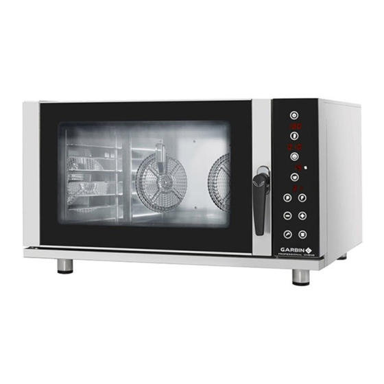
  • Seite 92: Digitales Steuerpaneel

    3.2.1 - DIGITALES STEUERPANEEL 25GE VAP / 45GE VAP / 46PE VAP / 61GE VAP / 64PE VAP / 101GE VAP / 104PEVAP Hauptschalter Display Temperatur LED Temperatur Temperaturtaste Display Zeit LED Kerntemperaturfühler Kerntemperaturfühler Taste Zeit Display Feuchtigkeit LED Feuchtigkeit...
  • Seite 93 3.2.1a - MODELLE 25GE VAP / 45GE VAP / 46PE VAP / 61GE VAP / 64PE VAP / 101GE VAP / 104PEVAP ON/OFF ANSCHALTEN UND ABSCHALTEN Wenn das Gerät mit Spannung versorgt wird, zeigt die Leiterplatte für einige Sekunden die Aufschrift der Software an. Dann geht der Ofen in den OFF Status und auf dem Display leuchtet das Led auf und bleibt in Warteposition.
  • Seite 94 3.2.1b - MODELLE 25GE VAP / 45GE VAP / 46PE VAP / 61GE VAP / 64PE VAP / 101GE VAP / 104PEVAP TASTE START/STOP Wenn man START/STOP drückt: Die Backzeit startet, das Licht innen schaltet sich ein, (der Start erfolgt nie weder während des Einstellens noch am Ende der Einstellung ohne den ausdrücklichen Befehl START).
  • Seite 95: Vorwärmen

    3.2.1c - MODELLE 25GE VAP / 45GE VAP / 46PE VAP / 61GE VAP / 64PE VAP / 101GE VAP / 104PEVAP TEMPERATURTASTE Einstellbar von 0 °C bis 270 °C Defaultwert für Temperatur: 100 °C Während eines Backvorganges können sich die eingestellten Daten ändern, wenn man die Taste Temperatur drückt, blinkt...
  • Seite 96: Taste Feuchtigkeit

    3.2.1d - MODELLE 25GE VAP / 45GE VAP / 46PE VAP / 61GE VAP / 64PE VAP / 101GE VAP / 104PEVAP TASTE FEUCHTIGKEIT Einstellbar von 0 bis 99 Default 00 Beispiel Zeiten: 100% gleich 60 Sek on; 50% gleich 30 Sek on und 30 Sek off;...
  • Seite 97 3.2.1e - MODELLE 25GE VAP / 45GE VAP / 46PE VAP / 61GE VAP / 64PE VAP / 101GE VAP / 104PEVAP PROGRAMME (PHASE) Der Ofen muss sich in der Position ”Leiterplatte angeschaltet” befinden, mit dem blinkenden Display Temperatur (Startphase).
  • Seite 98: Taste Manuelle Befeuchtung

    3.2.1f - MODELLE 25GE VAP / 45GE VAP / 46PE VAP / 61GE VAP / 64PE VAP / 101GE VAP / 104PEVAP BESONDERE BEFEHLE TASTE MANUELLE BEFEUCHTUNG Funktion nur mit einem aktiven Zyklus. Wenn man die Taste drückt, wird auf dem Display Feuchtigkeit die Zeit in Sekunden ausgedrückt für maximal 10 Sekunden...
  • Seite 99: Befehlspaneel Öfen Mit Encoder

    3.3.1 - BEFEHLSPANEEL ÖFEN MIT ENCODER 25GL VAP / 45GL VAP / 46PL VAP / 61GL VAP / 64PL VAP / 101GL VAP / 104PL VAP Display Temperatur Drehknopf Temperatur Display Zeit Drehknopf Zeit Display Feuchtigkeit Drehknopf Feuchtigkeit Display Kerntemperaturfühler* Drehknopf Kerntemperaturfühler* Hauptschalter...
  • Seite 100: On/Off Anschalten Und Abschalten

    3.3.1a - MODELLE 25GL VAP / 45GL VAP / 46PL VAP / 61GL VAP / 64PL VAP / 101GL VAP / 104PL VAP ON/OFF ANSCHALTEN UND ABSCHALTEN Wenn das Gerät mit Spannung versorgt wird, zeigt die Leiterplatte für einige Sekunden die Aufschrift der Software an. Dann geht der Ofen in den OFF Status und auf dem Display leuchtet das Led auf und bleibt in Warteposition.
  • Seite 101 3.3.1b - MODELLE 25GL VAP / 45GL VAP / 46PL VAP / 61GL VAP / 64PL VAP / 101GL VAP / 104PL VAP TASTE START/STOP Wenn man START/STOP drückt: Die Backzeit startet, das Licht innen schaltet sich ein. Das Display Temperatur geht von der Anzeige des eingestellten Set Points auf die Set Temperatur Kammer über und das entsprechende Led leuchtet solange auf bis der eingegebene Set Point erreicht ist, es schaltet ab, wenn der eingegebene...
  • Seite 102 3.3.1c - MODELLE 25GL VAP / 45GL VAP / 46PL VAP / 61GL VAP / 64PL VAP / 101GL VAP / 104PL VAP DREHKNOPF TEMPERATUR Einstellbar von 0 °C bis 270 °C Defaultwert für Temperatur: 100 °C Während eines Backzyklus können die eingegebenen Werte geändert werden, indem der Drehknopf Temperatur gedreht wird, an dieser Stelle blinkt das Display und der Vorgang der Dateneingabe wiederholt sich.
  • Seite 103: Drehknopf Feuchtigkeit

    3.3.1d - MODELLE 25GL VAP / 45GL VAP / 46PL VAP / 61GL VAP / 64PL VAP / 101GL VAP / 104PL VAP DREHKNOPF FEUCHTIGKEIT Einstellbar von 0 bis 99 Default 00 Beispiel Zeiten: 100% gleich 60 Sek on 50% gleich 30 Sek on und 30 Sek off 10% 6 Sek on 54 Sek off Das Display blinkt Defaultwert 0, wenn man den Drehknopf dreht, gebe ich den Wert ein.
  • Seite 104: Reinigung Und Ordentliche Wartung Des Gerätes

    3.3 - Nach dem Betrieb 1) Den Ofen ausschalten. 2) Schließen Sie die Wasserversorgungshähne. Schalten Sie die Stromversorgung mit dem Hauptschalter 3.4 - Reinigung und ordentliche Wartung des Gerätes • Zur Gewährleistung einer einwandfreien Funktionsweise, Hygiene und Leistung ist das Gerät täglich zu reinigen.
  • Seite 105: Primera Parte

    PRIMERA PARTE 1.1 - INTRODUCCIÓN Agradecemos la confianza que ha demostrado al adquirir uno de nuestros productos. Le aconsejamos que lea atentamente este manual antes de poner en marcha los hornos, ya que contiene toda la información necesaria para usarlos correctamente y para las operaciones de mantenimiento. La finalidad del presente manual es la de permitir al usuario, sobre todo al directo utilizador, de tomar todas las medidas y predisponer todos los medios, los recursos humanos y los materiales necesarios para una utilización segura y duradera de los hornos.
  • Seite 106 • Por este motivo les aconsejamos que se dirijan siempre al Concesionario que ha efectuado la venta, especificando el tipo de inconveniente, número de serie y el modelo de su equipo. • La instalación, así como cualquier reparación o puesta a punto que haya que realizar a continuación deberá...
  • Seite 107: Características Tècnicas Y Placa De Datos

    1.4 - Características tècnicas y placa de datos Modelo 25GE/25GL VAP 45GE/45GL VAP 46PE/46PL VAP Potencia eléctrica 3300 W 7000 W 7000 W Alimentación 230V~; 50/60 Hz 400V~ 3N; 50/60 Hz 400V~ 3N; 50/60 Hz Conexión eléctrica tipo “X” tipo “X” tipo “X”...
  • Seite 108 1.4.1 - Características tècnicas y placa de datos Modelo 61GE/61GL VAP 64PE/64PL VAP Potencia eléctrica 9400 W 9400 W Alimentación 400V~ (3N); 50/60 Hz 400V~ (3N); 50/60 Hz Conexión eléctrica tipo “X” tipo “X” Peso 70 kg 70 kg Dimensiones (en mm) 965 x 830 x 770 965 x 830 x 770 Capacidad...
  • Seite 109: Conformidad Con Las Directivas

    1.5 - Desplazamiento, transporte y descarga • La empresa realiza el embalaje de las máquinas en función de los acuerdos tomados y dependiendo del país de destinación y del medio de transporte utilizado. • Despuès de la instalación, el embalaje puede ser reutilizado o eliminado respetando las normas vigentes en el país del comprador.
  • Seite 110: Lugar De Instalación Y Colocación

    SEGUNDA PARTE 2.0 - Instrucciones para la instalación y el mantenimiento 2.1 - Lugar de instalación y colocación ADVERTENCIA La instalación, la transformación y el mantenimiento extraordinario del horno deben ser realizados exclusivamente por instaladores autorizados o por el Ente suministrador de la energía y en conformidad con las normativas de seguridad en vigor.
  • Seite 111: Conexión Eléctrica

    Antes de poner en funcionamiento el horno, quitar la película protectiva de las partes externas del horno; los eventuales residuos de cola que pueden quedar sobre las superficies tienen que ser eliminados con un disolvente adecuado. Los hornos pueden ser instalan sobre un banco fijo (con soportes) o bien sobre un adecuado caballete de apoyo proporcionado por el fabricante como accesorio.
  • Seite 112: Conexión A La Red Hídrica

    2.3 - LINEA DE TIERRA • El equipo debe estar conectado a la línea de tierra de la red. • A tal fin, se puede acceder al tablero de bornes de alimentación desde la parte posterior del horno. • El hilo amarillo/ verde del cable de alimentación tiene que quedar fijado a la bornera marcada con el símbolo (véase fig.
  • Seite 113: Puesta En Marcha

    2.6 - Puesta en marcha Controlar: • La correcta instalación del horno, su estabilidad y que estè perfectamente nivelado. • La correcta realización de la conexión elèctrica, conformidad del cable elèctrico, presencia y eficacia del interruptor omnipolar y de la instalación elèctrica. •...
  • Seite 114 Recordarse de restablecer los prensaestopas, los sellantes y las vainas introducidas antes de terminar el trabajo. 2.9.1 - Sustitución del termostato de seguridad • 1) Abrir el lateral derecho del horno; 2) Desenroscar el bulbo del interior de la celda del horno; 3) Extraer los cables del termostato y desenroscar la fijación (B - fig.
  • Seite 115 2.9.3 - Prensaestopas de la puerta • El prensaestopas se introduce a presión y debe sacarse tirándolo y colocarse nuevamente a presión. Dicha operación debe realizarse a mano para no dañar el prensaestopas. fig . 10 2.9.4 - Ventilador y motor •...
  • Seite 116: Advertencias Preliminares

    TERCERA PARTE INSTRUCCIONES DE USO 3.1 - Advertencias preliminares • La máquina está destinada a un uso profesional y debe ser utilizada por personal preparado. • El horno debe emplearse exclusivamente para la cocción de alimentos. Cualquier otro uso se considera impropio.
  • Seite 117: Panel De Control Digital

    3.2.1 - PANEL DE CONTROL DIGITAL 25GE VAP / 45GE VAP / 46PE VAP / 61GE VAP / 64PE VAP / 101GE VAP / 104PEVAP Interruptor general Pantalla temperatura LED temperatura Tecla temperatura Pantalla tiempo LED sonda al corazón Sonda al corazón...
  • Seite 118 3.2.1a - MODELOS 25GE VAP / 45GE VAP / 46PE VAP / 61GE VAP / 64PE VAP / 101GE VAP / 104PEVAP ON/OFF ENCENDIDO Y APAGADO Cuando se conecta la tensión, la tarjeta muestra durante algunos segundos la versión del software. Después el horno se pone en estado de OFF y se enciende en la pantalla tiempo el Led y permanece en espera.
  • Seite 119 3.2.1b - MODELOS 25GE VAP / 45GE VAP / 46PE VAP / 61GE VAP / 64PE VAP / 101GE VAP / 104PEVAP Tecla START-STOP Presionando la tecla START-STOP: inicia el ciclo de cocción, se activa la luz interna (el inicio de la cocción no se produce jamás durante la programación ni...
  • Seite 120: Tiempo De Cocción

    3.2.1c - MODELOS 25GE VAP / 45GE VAP / 46PE VAP / 61GE VAP / 64PE VAP / 101GE VAP / 104PEVAP TECLA TEMPERATURA Se puede configurar de 0 °C a 270 °C Valor predeterminado para la temperatura: 100 °C Durante un ciclo de cocción se pueden modificar los datos...
  • Seite 121 3.2.1d - MODELOS 25GE VAP / 45GE VAP / 46PE VAP / 61GE VAP / 64PE VAP / 101GE VAP / 104PEVAP TECLA HUMEDAD Se puede configurar de 0 a 99 Predeterminado 00 Ejemplo de tiempos: 100% igual a 60 seg on 50% igual 30 seg on y 30 seg.
  • Seite 122 3.2.1e - MODELOS 25GE VAP / 45GE VAP / 46PE VAP / 61GE VAP / 64PE VAP / 101GE VAP / 104PEVAP PROGRAMAS (FASE) El horno debe encontrarse en la posición de tarjeta encendida con la pantalla de temperatura que parpadea (fase inicial).
  • Seite 123 3.2.1f - MODELOS 25GE VAP / 45GE VAP / 46PE VAP / 61GE VAP / 64PE VAP / 101GE VAP / 104PEVAP MANDOS PARTICULARES TECLA HUMIDIFICACIÓN MANUAL Función sólo con un ciclo activo. Presionando la tecla se visualiza en la pantalla humedad el tiempo en segundos durante un máximo de 10 segundos, se...
  • Seite 124: Panel De Mandos Hornos Con Codificador

    3.3.1 - PANEL DE MANDOS HORNOS CON CODIFICADOR 25GL VAP / 45GL VAP / 46PL VAP / 61GL VAP / 64PL VAP / 101GL VAP / 104PL VAP Pantalla temperatura Pomo de la temperatura Pantalla tiempo Pomo del tiempo Pantalla humedad Pomo de la humedad Pantalla sonda al corazón* Pomo de la sonda al...
  • Seite 125 3.3.1a - MODELOS 25GL VAP / 45GL VAP / 46PL VAP / 61GL VAP / 64PL VAP / 101GL VAP / 104PL VAP ON/OFF ENCENDIDO Y APAGADO Cuando se conecta la tensión, la tarjeta muestra durante algunos segundos la versión del software. Después el horno se pone en estado de OFF y se enciende en la pantalla tiempo el Led y permanece en espera.
  • Seite 126 3.3.1b - MODELOS 25GL VAP / 45GL VAP / 46PL VAP / 61GL VAP / 64PL VAP / 101GL VAP / 104PL VAP Tecla START-STOP Presionando la tecla START-STOP: inicia el ciclo de cocción, se activa la luz interna. La pantalla temperatura pasa desde la visualización set point programado a set temperatura cámara y el relativo LED se enciende hasta alcanzar el punto de ajuste programado;...
  • Seite 127 3.3.1c - MODELOS 25GL VAP / 45GL VAP / 46PL VAP / 61GL VAP / 64PL VAP / 101GL VAP / 104PL VAP POMO DE LA TEMPERATURA Se puede configurar de 0 °C a 270 °C Valor predeterminado para la temperatura: 100 °C Durante un ciclo de cocción se pueden modificar los datos programados, girando el pomo de temperatura.
  • Seite 128 3.3.1d - MODELOS 25GL VAP / 45GL VAP / 46PL VAP / 61GL VAP / 64PL VAP / 101GL VAP / 104PL VAP POMO DE LA HUMEDAD Se puede configurar de 0 a 99 Predeterminado 00 Ejemplo de tiempos: 100% igual a 60 seg. on 50% igual 30 seg on y 30 seg.
  • Seite 129 3.4 - Operaciones después del uso 1) Apagar el horno 2) Cerrar las llaves de alimentación del agua. Desarmar el interruptor general de alimentación eléctrica. 3.5 - Limpieza y mantenimiento rutinario del horno • Los hornos deben limpiarse cotidianamente para garantizar la máxima funcionalidad, higiene y rendimiento.
  • Seite 130 4.0 - Schemi elettrici - Wiring diagrams - Schémas électriques Schaltpläne - Esquemas eléctricos 25GE VAP 25GL VAP...
  • Seite 131 4.0 - Schemi elettrici - Wiring diagrams - Schémas électriques Schaltpläne - Esquemas eléctricos 46PE VAP 45GE VAP 45GL VAP...
  • Seite 132 4.0 - Schemi elettrici - Wiring diagrams - Schémas électriques Schaltpläne - Esquemas eléctricos 61GE VAP 61GL VAP 64PE VAP...
  • Seite 133 4.0 - Schemi elettrici - Wiring diagrams - Schémas électriques Schaltpläne - Esquemas eléctricos 101GE VAP 101GL VAP 104PE VAP...
  • Seite 134 4.0 - Schemi elettrici - Wiring diagrams - Schémas électriques Schaltpläne - Esquemas eléctricos 46PL VAP...
  • Seite 135 4.0 - Schemi elettrici - Wiring diagrams - Schémas électriques Schaltpläne - Esquemas eléctricos 64PL VAP...
  • Seite 136 4.0 - Schemi elettrici - Wiring diagrams - Schémas électriques Schaltpläne - Esquemas eléctricos 104PL VAP...
  • Seite 137 AVVERTENZA IL COSTRUTTORE DECLINA OGNI RESPONSABILITÁ PER LE POSSIBILI INESATTEZZE CONTENUTE NEL PRESEN- TE OPUSCOLO IMPUTABILI AD ERRORI DI TRASCRIZIONE O STAMPA. SI RISERVA INOLTRE IL DIRITTO DI APPORTARE AL PRODOTTO QUELLE MODIFICHE CHE RITIENE UTILI O NECES- SARIE, SENZA PREGIUDICARNE LE CARATTERISTICHE ESSENZIALI. IL COSTRUTTORE DECLINA OGNI E QUALSIASI RESPONSABILITÁ...
  • Seite 138 Garbin srl Via Fontanelle 6 36050 Monteviale (Vicenza) Italy Ph. +39 0444.552221 Fax +39 0444.952619 garbin@garbinovens.eu www.garbinovens.com...

Inhaltsverzeichnis