Herunterladen Inhalt Inhalt Diese Seite drucken

Werbung

Verfügbare Sprachen
  • DE

Verfügbare Sprachen

(EN) J4C 20 TO 300 INSTALLATION INSTRUCTIONS
(ES) INSTUCCIONES PUESTA EN MARCHA J4C 20 A 300
(FR) INTRUCTIONS D'INSTALLATION J4C 20 A 300
(IT) ISTRUZIONI DI INSTALLAZIONE J4C DA 20 A 300
(DE) KURZANLEITUNG J4C S20-S300

Werbung

Inhaltsverzeichnis
loading

Inhaltszusammenfassung für J+J J4C S Serie

  • Seite 1 (EN) J4C 20 TO 300 INSTALLATION INSTRUCTIONS (ES) INSTUCCIONES PUESTA EN MARCHA J4C 20 A 300 (FR) INTRUCTIONS D’INSTALLATION J4C 20 A 300 (IT) ISTRUZIONI DI INSTALLAZIONE J4C DA 20 A 300 (DE) KURZANLEITUNG J4C S20-S300...
  • Seite 2: Inhaltsverzeichnis

    INDEX J4C 20 TO 300 INSTALLATION INSTRUCTIONS (ENGLISH) 1. VOLTAGE ..................................2. ELECTRICAL CONNECTORS ..........................3. LOCAL VISUAL POSITION INDICATOR ......................4. EMERGENCY MANUAL OVERRIDE FACILITY ..................... 5. EXTERNAL LED LIGHT STATUS ........................... 6. BSR - NC/NO SET-UP ............................7. DPS ....................................
  • Seite 3: Voltage

    ENGLISH - J4C 20 TO 300 INSTALLATION INSTRUCTIONS READ THESE INSTRUCTIONS BEFORE CONNECTING THE ACTUATOR. DAMAGE CAUSED BY NON COMPLIANCE OF THESE INSTRUCTIONS IS NOT COVERED BY OUR WARRANTY. J4C Electric actuators operate with the use of live electricity. It is recommended that only qualified electrical engineers be allowed to connect or adjust these actuators.
  • Seite 4: Local Visual Position Indicator

    ENGLISH - J4C 20 TO 300 INSTALLATION INSTRUCTIONS Electrical connection: All models. ON - OFF VAC The power supply is connected to the grey “A” DIN plug (Fig.3). Neutral PIN 1 + Phase PIN 2 = Close actuator Neutral PIN 1 + Phase PIN 3= Open actuator Earth/ground connection - Flat PIN on top.
  • Seite 5: Emergency Manual Override Facility

    ENGLISH - J4C 20 TO 300 INSTALLATION INSTRUCTIONS 4. EMERGENCY MANUAL OVERRIDE FACILITY The J4C has 2 operating modes, automatic and manual, the required mode is selected by using a lever on the lower half of the actuator housing (Fig 7). The 2 positions are marked: AUTO = Automatic operation MAN = Manual operation...
  • Seite 6: External Led Light Status

    ENGLISH - J4C 20 TO 300 INSTALLATION INSTRUCTIONS 5. EXTERNAL LED LIGHT STATUS The LED status light provides visual communication between the actuator and the user. The current operational status of the actuator is shown by either solid lit, or different flashing sequences of the LED light: Fig.8 6.
  • Seite 7: Dps

    ENGLISH - J4C 20 TO 300 INSTALLATION INSTRUCTIONS 7. DPS Use the configuration you need by moving the DIPs: In order to set the actuator up, use the DIPs shown in picture . Fig.10 External adjustment B. plug - Connect a cable between PIN 1 (on the right side) and PIN Earth (on the bottom) (Fig.
  • Seite 8: Mounting To Component Being Actuated

    ENGLISH - J4C 20 TO 300 INSTALLATION INSTRUCTIONS 9. MOUNTING TO COMPONENT BEING ACTUATED (EX:1/4 TURN VALVE) It is vital that the mounting kit used to connect the electric actuator to the component (ex: valve) is correctly manufactured and assembled. The mounting bracket’s holes must be drilled to ensure that the centerline of the actuator’s drive is perfectly in line with the component’s drive-centerline, and that the drive coupling/ adaptor rotates around this centerline.
  • Seite 9: Voltaje

    LEA ATENTAMENTE ESTAS INSTRUCCIONES ANTES DE LA CONEXIÓN DEL ACTUADOR. EL INCUMPLIMIENTO DE ESTAS INSTRUCCIONES DEJA SIN EFECTO TODO TIPO DE GARANTÍA. Los actuadores J+J series J4C 20 a 300 utilizan energía eléctrica para su funcionamiento. Recordamos que tan solo personal especializado efectúe las conexiones o ajustes del actuador.
  • Seite 10: Indicador Visual

    ESPAÑOL - INSTUCCIONES PUESTA EN MARCHA J4C 20 A 300 Conexiones Eléctricas estándares, para todos los modelos. ON - OFF VAC Conectar el voltaje al conector gris “A” (Fig.3). PIN 1 neutro + PIN 2 fase = Actuador cierra PIN 1 neutro + PIN 3 fase = Actuador abre Conectar el cable tierra en el PIN ↓...
  • Seite 11: Mando Manual De Emergencia

    ESPAÑOL - INSTUCCIONES PUESTA EN MARCHA J4C 20 A 300 4. MANDO MANUAL DE EMERGENCIA En una de las caras exteriores del actuador se encuentra la palanca selectora (Fig 7). AUTO = Operación Automática. MAN = Operación Manual. ATENCIÓN, no desatornillar nunca el tornillo de seguridad de la palanca selectora, ni utilizar ningu- na herramienta para moverla, ya que pueden producirse importantes daños en el sistema mecánico.
  • Seite 12: Indicador Luminoso

    ESPAÑOL - INSTUCCIONES PUESTA EN MARCHA J4C 20 A 300 5. INDICADOR LUMINOSO Es un sistema de comunicación entre el actuador y el usuario. Según el tipo de lumínica nos informa de (Fig.8): Fig.8 6. BSR-CONFIGURACIÓN BSR NC - BSR NO Si la unidad dispone de un sistema BSR, en caso de fallo de alimentación, el actuador irá...
  • Seite 13: Dps

    ESPAÑOL - INSTUCCIONES PUESTA EN MARCHA J4C 20 A 300 7. DPS Configuraciones posibles dependiendo de la señal de instrumentación a trabajar. Situar los DIPS (Fig.10), en la posición indicada en la parte inferior, Fig.10 dependiendo de la señala a trabajar. Autoajuste externo: Conector B - Hacer un cruce entre el PIN1 (PIN derecha) y el PIN TIERRA (PIN inferior).
  • Seite 14: Montaje De Los Componentes Al Actuador

    ESPAÑOL - INSTUCCIONES PUESTA EN MARCHA J4C 20 A 300 9. MONTAJE DE LOS COMPONENTES AL ACTUADOR Es vital que el “KIT” de montaje para ensamblar el actuador a la válvula esté correctamente mecani- zado y montado. Los taladros de las torretas/soportes deben de estar perfectamente mecanizados y alineados para asegurar precisamente el perfecto alineamiento entre el actuador, las piezas de conexión y la válvula.
  • Seite 15: Tension

    LIRE ATTENTIVEMENT CES INSTRUCTIONS AVAN LE RACCORDEMENT DE L’ACTIONNEUR LE NON-RESPECT DE CES INSTRUCTIONS ANNULE TOUT TYPE DE GARANTIE Les actionneurs J+J Séries J4C 20 à 300 utilisent de l’énergie électrique pour leur fonctionnement. Nus rappelons que, seul, le personnel spécialisé peut effectuer les branchements ou les réglages de l’actionneur.
  • Seite 16: Indicateur Visuel

    FRANÇAIS - INTRUCTIONS D’INSTALLATION J4C 20 A 300 Raccordements électriques standard pour tous les modèles ON - OFF VAC Raccorder l’alimentation au connecteur gris “A” (Fig. 3) BORNE 1 neutre + BORNE 2 phase = l’actionneur se ferme BORNE 1 neutre + BORNE 3 phase = l'actionneur s’ouvre Raccorder le câble à...
  • Seite 17: Commande Manualle D'urgence

    FRANÇAIS - INTRUCTIONS D’INSTALLATION J4C 20 A 300 4. COMMANDE MANUALLE D'URGENCE Le levier (Fig. 7) se trouve sur l’une des faces extérieures de l’actionneur AUTO = opération automatique MAN = opération manuelle ATTENTION : ne jamais deviser la vis de sécurité du levier sélecteur, ni utiliser d’outils pour le déplacer. Cela pourrait produire d’importants dommages dans le système mécanique.
  • Seite 18: Indicateur Lumineux

    FRANÇAIS - INTRUCTIONS D’INSTALLATION J4C 20 A 300 5. INDICATEUR LUMINEUX Système de communication entre l’actionneur et l’utilisateur (Fig.8) Fig.8 6. BSR: CONFIGURATION BSR NC - BSR NO Si l’unité dispose d’un système BSR (max. 3 minutes), en cas de panne de courant, l’actionneur ira en position prédéterminée “NO”...
  • Seite 19: Dps

    FRANÇAIS - INTRUCTIONS D’INSTALLATION J4C 20 A 300 7. DPS Configurations possibles en fonction du signal analogique à travailler Situer les DIPS (Fig.10) dans la position indiquée sur la partie inferieur, en fonction du signal à utiliser Fig.10 Auto-régulation externe Connecteur centrale “B”...
  • Seite 20: Montage Des Composants De L'actionneur

    FRANÇAIS - INTRUCTIONS D’INSTALLATION J4C 20 A 300 9. MONTAGE DES COMPOSANTS DE L’ACTIONNEUR Il est indispensable que le “KIT” de montage, pour assembler l’actionneur à la vanne, soit usiné et monté correctement. Les trous des supports doivent être parfaitement alignés pour assurer un alignement parfait entre l'actionneur, les pièces de raccordement et la vanne.
  • Seite 21: Tensione

    IL MANCATO RISPETTO DI QUESTE ISTRUZIONI COMPORTA L'ANNULLAMENTO DI QUALSIASI GARANZIA. Per il loro funzionamento, gli attuatori J+J serie J4C da 20 a 300 utilizzano energia elettrica. Ricordiamo che soltanto personale specializzato deve effettuare i collegamenti o le regolazioni dell'attuatore.
  • Seite 22: Indicatore

    ITALIANO - ISTRUZIONI DI INSTALLAZIONE J4C DA 20 A 300 Collegamenti elettrici standard, per tutti i modelli ON - OFF VAC Collegare la tensione al connettore grigio “A” (Fig. 3). PIN 1 neutro + PIN 2 fase = l'attuatore si chiude. PIN 1 neutro + PIN 3 fase = l'attuatore si apre.
  • Seite 23: Comando Manuale D'emergenza

    ITALIANO - ISTRUZIONI DI INSTALLAZIONE J4C DA 20 A 300 4. COMANDO MANUALE D'EMERGENZA La leva selettrice (Fig. 7) si trova su uno dei lati esterni dell'attuatore. AUTO = Funzionamento automatico. MAN = Funzionamento manuale. ATTENZIONE: non svitare mai la vite di sicurezza della leva selettrice, né utilizzare alcun utensile per spostarla.
  • Seite 24: Spia Luminosa

    ITALIANO - ISTRUZIONI DI INSTALLAZIONE J4C DA 20 A 300 5. SPIA LUMINOSA Si tratta di un sistema di comunicazione tra l'attuatore e l'operatore: a seconda del tipo di luce fornisce le seguenti informazioni (Fig.8) Fig.8 6. BSR: CONFIGURAZIONE BSR NC - BSR NO Se l'unità...
  • Seite 25: Dps

    ITALIANO - ISTRUZIONI DI INSTALLAZIONE J4C DA 20 A 300 7. DPS Configurazioni possibili in funzione del segnale della strumentazione su cui agire. Collocare i DIPS (Fig.10) nella posizione indicata in basso, a seconda Fig.10 del segnale da utilizzare. Auto-regolazione esterna Connettore centrale “B”...
  • Seite 26: Montaggio Dei Componenti All'attuatore

    ITALIANO - ISTRUZIONI DI INSTALLAZIONE J4C DA 20 A 300 9. MONTAGGIO DEI COMPONENTI ALL'ATTUATORE È fondamentale che il kit fornito per l'assemblaggio dell'attuatore alla valvola sia montato corretta- mente. I fori delle torrette/supporti devono essere perfettamente allineati per garantire un perfetto allineamento tra l'attuatore, le parti di collegamento e la valvola.
  • Seite 27: Produktbeschreibung

    Anderenfalls können langfristig Beschädigungen oder ein Funktionsausfall entstehen. Umfeld und Einbaulage J+J Antriebe dürfen nicht über Kopf (Flansch nach oben) eingebaut werden. Es ist immer auf die Zugänglichkeit der Handnotbe- tätigung und Sichtbarkeit von Stellungsanzeiger und Status-LED zu achten. Bei Anwendungen mit Vibrationen in der Rohrleitung sind Leitungskompensatoren vorzusehen.
  • Seite 28: Elektrischer Anschluss

    Jeder Stecker wird mit einer Schraube am Schwenkantrieb befestigt, diese darf nicht überdreht werden. J+J Schwenkantriebe sind einphasig anzuschließen und müssen über Relais oder Schalter angesteuert werden. Für die Ansteuerung stehen je nach Bedarf drei verschiedene Beschaltungsmethoden ohne Umkonfiguration zur Verfügung.
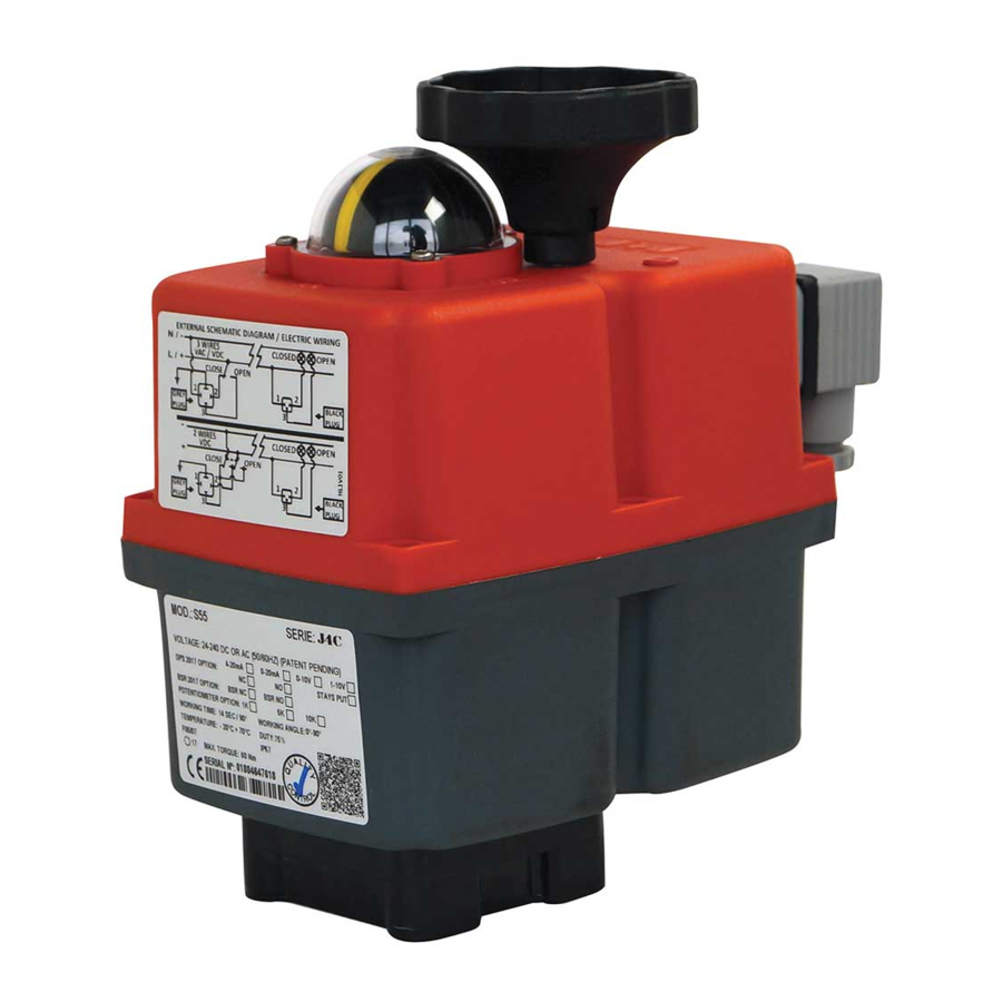
  • Seite 29: Modellübergreifend

    Kurzanleitung J4C S20-S300 Übersicht Bezeichnung 140-300 20-35-55-85 A Umschalter Handbetätigung B Handrad C DOME Stellungsanzeiger D Status LED E Schaltplan F Typenschild Modellübergreifend: Temperaturbereich Einschaltdauer Leistung Heizung Schutzart IEC60529 2x Endlagenschalter ED= 75% -20°C - +70°C 3,5 W IP67 SPST NO 5A 125VAC / 3A 250VAC Optional 0,1A 30VDC (siehe Seite 1) Modellspezifisch: Stromaufnahme bei max.
  • Seite 30: Nockensystem Einstellanleitung

    Kurzanleitung J4C S20-S300 Nockensystem Einstellanleitung Mit Hilfe des Nockensystems können der Schwenkwinkel, sowie die Endlagenrückmeldung des Antriebs eingestellt werden. Der Antrieb ist ab Werk vorjustiert (siehe Typenschild). Abhängig von Anwendung, Armatur oder mangelndem Fluchten von Armaturenverbindungen oder Adaptern kann es notwendig sein, dass der Antrieb in seinem Verfahrweg angepasst werden muss. Sämtliche Arbeiten am geöffneten Antrieb dürfen nur unter Schutzkleinspannung oder im spannungslosen Zustand und von entsprechend qualifiziertem Fachpersonal durchgeführt werden.

Inhaltsverzeichnis