ECOLAB MULTILINE 1000 Kurz- Betriebsanleitung
Elektro-pneumatisches dosiergerät

Verwandte Anleitungen für ECOLAB MULTILINE 1000


Inhaltszusammenfassung für ECOLAB MULTILINE 1000
- Seite 1 Kurzbetriebsanleitung Short operating instructions MULTILINE Elektro-pneumatisches Dosiergerät Electro-pneumatic metering unit DEUTSCH ENGLISH KBA Multiline 417102603 Rev. 1-02.2020 20.02.2020...
-
Seite 3: Übersicht Der Betriebsanleitungen
Übersicht der Betriebsanleitungen Pumpentyp Sprache Artikel Nr. QR - Code Links https://www.ecolab-engineering.de/fileadmin/ download/bedienungsanleitungen/ads/ Multiline 1000 417101357 Bedienungsanleitungen-ADS/ 417101357_Multiline1000.pdf https://www.ecolab-engineering.de/fileadmin/ Deutsch / download/bedienungsanleitungen/ads/ Multiline 1000 S Englisch / 417101439 Bedienungsanleitungen-ADS/ Französisch 417101439_Multiline1000_S.pdf https://www.ecolab-engineering.de/fileadmin/ download/bedienungsanleitungen/ads/ Multiline 6000 417101369 Bedienungsanleitungen-ADS/ 417101369_Multiline_6000.pdf 417102603 Rev. 1-02.2020... - Seite 4 Rufen sie den "Google Play Store" mit Ihrem Smartphone /Tablet auf. Geben Sie den Namen „Ecolab DocuAPP“ im Suchfeld ein. Wählen Sie anhand des Suchbegriffes Ecolab DocuAPP in Verbindung mit diesem Symbol die „Ecolab DocuApp“ aus. Betätigen Sie den Button [installieren].
- Seite 5 Die Überlassung dieser Anleitung an Dritte, Vervielfältigungen in jeglicher Art und Form, auch auszugsweise, sowie die Verwertung und/oder Mitteilung des Inhaltes sind ohne schriftliche Genehmigung von Ecolab Engineering (im folgenden "Hersteller”) außer für interne Zwecke nicht gestattet. Zuwiderhandlungen verpflichten zu Schadenersatz.
-
Seite 6: Allgemeine Sicherheitshinweise
Sicherheit Sicherheit Allgemeine Sicherheitshinweise GEFAHR! Wenn anzunehmen ist, dass ein gefahrloser Betrieb nicht mehr möglich ist, so ist das Gerät unverzüglich außer Betrieb zu nehmen und gegen unabsichtlichen Betrieb zu sichern. Das ist der Fall: – wenn sichtbare Beschädigungen auftreten, –... - Seite 7 Sicherheit VORSICHT! Zur bestimmungsgemäßen Verwendung gehört auch die Einhaltung aller vom Hersteller vorgeschriebenen Bedienungs- und Betriebsanweisungen sowie alle Wartungs- und Instandhaltungsbedingungen. Siehe Ä Kapitel 1.1 „Hinweis zur Betriebsanleitung“ auf Seite 2. Eigenmächtige Umbauten oder Veränderungen sind nur nach Absprache und mit Genehmigung des Herstellers zulässig. Originalersatzteile und vom Hersteller autorisiertes Zubehör dienen der Sicherheit.
- Seite 8 Aufbau Aufbau Aufbau des MULTILINE 1000 Abb. 1: Aufbau des MULTILINE 1000 LC-Display Funktion: Anzeige „Alarm“ (rot) Das Betätigen dieser Taste bewirkt eine Umschaltung Funktion: zwischen Automatik und Dauerbetrieb. Die Blinkt, wenn eine Störung vorliegt oder die entsprechend zugehörige LED leuchtet auf.
-
Seite 9: Aufbau Des Multiline 1000 S
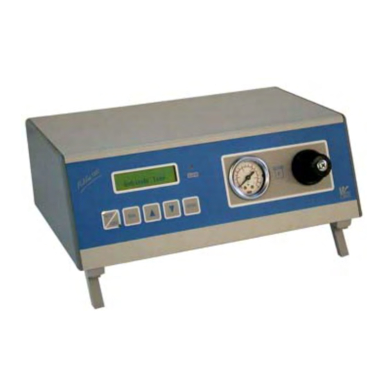
Aufbau Aufbau des Multiline 1000 S Abb. 2: Frontansicht LC-Display Verstellung Dosierzeit bzw. Eingabe nach oben LED Anzeige „Alarm“ (rot): Taste für Manuellbetrieb „MAN“ : Blinkt bei Störung oder Leermeldung. Genauere Aktivierung manueller Betrieb Anzeige im Display Umschalttaste Dauer- Manometer: Automatikbetrieb „AUTO / CONT“... -
Seite 10: Aufbau Des Multiline 6000
Aufbau Aufbau des Multiline 6000 Abb. 4: Aufbau Optionale Steuerdruckeinheit Optionaler Steuerausgang Ventile (max. 6 Stück) Optionale Behälterdruckeinheit Optionaler Behälterdruckanschluss Netzschalter Optionaler Druckluftanschluss Netzanschluss Bedientasten Optionaler Schalldämpfer 10 Display 417102603 Rev. 1-02.2020... - Seite 11 Schutzbrille Sicherheitsschuhe Installationsarbeiten 4.1.1 Multiline 1000 und Multiline 1000 S VORSICHT! Das Gerät ist auf 230 V Netzspannung voreingestellt! Liegt 115 V Netzspannung vor, so muss der Spannungswähleinsatz (Pos. 1) um 180° gedreht und die Sicherung (Pos. 2) gegen die beiliegende 115 V Sicherung (250 mA) ausgetauscht werden.
- Seite 12 Installation und Erstinbetriebnahme 4.1.1.1 Anschluss des Startsignalkabels Bei der Verwendung eines Fußschalters als Startsignalgeber sind die Kabel bereits mit den entsprechenden Steckern vorkonfektioniert. Bei Anschluss an eine Steuerung muss der Stecker kundenseitig konfektioniert werden. Anschlussstecker kabelseitig: Abb. 6: Anschlussstecker kabelseitig Startsignal Common (gemeinsamer Anschluss zu Alarmausgang Alarmausgang (max.
- Seite 13 Der erforderliche Ventilsteuerdruck muss mindestens 0,5 MPa (5 bar) betragen. Die Druckluft muss frei von Feuchtigkeit und Öl sein, da sonst die Eigenschaften der Klebstoffe stark verändert werden können. Inbetriebnahme 4.2.1 Multiline 1000 und Multiline 1000 S Richtwerte Angabe Wert Einheit Viskosität bis 150 mPa.s (cp): 0,02 (0,2) MPa (bar) Viskosität bis 2 000 mPa.s (cp):...
- Seite 14 Installation und Erstinbetriebnahme 4.2.1.2 Inbetriebnahme Multiline 1000 S Druckluftausgang 1a des Multiline 1000-S über einen externen Druckregler mit dem Druckbehälter verbinden. Druckregler auf Minimaldruck einstellen. VORSICHT! Ausgang 1a ist ein direkter Abzweig vom Druckluftanschluss 12 des Multiline 1000-S. Der Druckbehälter darf nicht ohne Druckregler an das Druckluftnetz angeschlossen werden.
- Seite 28 / revision: Letze Änderung: 20.02.2020 last changing: Copyright Ecolab Engineering GmbH, 2020 Alle Rechte vorbehalten All rights reserved Nachdruck, auch auszugsweise, nur mit Genehmigung der Firma Ecolab Engineering GmbH Reproduction, also in part, only with permission of Ecolab Engineering GmbH...