SMA SUNNY HIGHPOWER PEAK1 Installationsanleitung
Vorschau ausblenden
Andere Handbücher für SUNNY HIGHPOWER PEAK1:
- Installationsanleitung (192 Seiten) ,
- Technische information (62 Seiten) ,
- Bedienungsanleitung (16 Seiten)
Inhaltsverzeichnis
Werbung
Verfügbare Sprachen
Verfügbare Sprachen
Werbung
Inhaltsverzeichnis
Fehlerbehebung

Verwandte Anleitungen für SMA SUNNY HIGHPOWER PEAK1


Inhaltszusammenfassung für SMA SUNNY HIGHPOWER PEAK1
- Seite 1 Installation Guide / Installationsanleitung / Instrucciones de instalación / Istruzioni per l’installazione / Instructions d’installation SUNNY HIGHPOWER PEAK1 SUNNY TRIPOWER 60 SHP75-10-STP60-10-IA-xx-19 | 139R0183 | Version 1.9...
-
Seite 3: Inhaltsverzeichnis
SMA Solar Technology AG ENGLISH - Table of Contents 1 Notes on this Document....... 13 1.1 Validity. - Seite 4 SMA Solar Technology AG 5.11 PV Connection ......... . 29 5.11.1 External PV Array Junction Boxes.
- Seite 5 SMA Solar Technology AG DEUTSCH - Inhaltsverzeichnis 1Hinweise zum Dokument ....... 52 1.1 Gültigkeitsbereich .
- Seite 6 SMA Solar Technology AG 5.10 Ethernet-Anschlüsse ........70 5.11 PV-Anschluss .
- Seite 7 SMA Solar Technology AG ESPAÑOL - Índice 1 Indicaciones sobre el documento ..... . . 96 1.1 Área de validez ......... 96 1.2 Grupo de destinatarios .
- Seite 8 SMA Solar Technology AG 5.10 Conexiones de ethernet........114 5.11 Conexión fotovoltaica .
- Seite 9 SMA Solar Technology AG ITALIANO - Indice 1 Note relative al documento......144 1.1 Ambito di validità.
- Seite 10 SMA Solar Technology AG 5.11 Collegamento dell’impianto FV ......161 5.11.1 Quadri di parallelo stringhe esterni ......161 5.11.2 Requisiti dei cavi .
- Seite 11 SMA Solar Technology AG FRANÇAIS - Table des matières 1 Remarnues relatives au document ..... 190 1.1 Champ d’application........190 1.2 Groupe cible .
- Seite 12 SMA Solar Technology AG 5.10 Raccordements Ethernet ....... . . 208 5.11 Raccordement photovoltaïque.
-
Seite 13: Notes On This Document
1 Notes on this Document The information contained in these documents is the property of 1.1 Validity SMA Solar Technology AG. No part of this document may be reproduced, stored in a retrieval system, or transmitted, in any This document is valid for: form or by any means, be it electronic, mechanical, •... -
Seite 14: Symbols In The Document
1 Notes on this Document SMA Solar Technology AG Abbreviat Description Symbol Explanation Indicates a situation which, if Hard Disk Drive not avoided, can result in International Electrotechnical property damage Commission international standards 1.5 Symbols in the Document organization Isolated Terra... -
Seite 15: Additional Information
1.8 Additional Information 30 m and an own power transformer is used. Additional information is available at Use SMA products only in accordance with the www.SMA-Solar.com: information provided in the enclosed documentation • Quick reference guide for the installation of the... -
Seite 16: Important Safety Instructions
2 Safety SMA Solar Technology AG compliance or non-compliance with such laws or codes in connection with the installation of the product. Danger to life due to electric shock when live The type label must remain permanently attached to components or DC cables are touched the product. - Seite 17 SMA Solar Technology AG 2 Safety Danger to life due to fre or explosion Danger to life due to electric shock from destruction of the measuring device due to In rare cases, an explosive gas mixture can be overvoltage generated inside the inverter under fault conditions. In...
-
Seite 18: Product Overview
Damage to the enclosure seal in subfreezing Prior to recommissioning SMA inverters after conditions the installation of SMA components or power If you open the inverter when temperatures are assemblies which cannot be replaced below freezing, the enclosure seals can be intuitively, ensure that the grounding conductor damaged. -
Seite 19: Dc Load-Break Switch
SMA Service Line. You will fnd the following Danger information on the type label: This symbol indicates that the •... -
Seite 20: System Overview
The PV array junction box enables the bundling and servicing of the inverter via the of the necessary number of PV strings for the SMA Inverter Manager. The LCS-Tool is the inverter. Each inverter requires a PV array primary user interface for the PV system. -
Seite 21: Unpacking
• Accessories bag containing: drive. The PC must be connected to the system 6 wall plugs 8 x 50 mm network of the SMA Inverter Manager. For setup via the LCS-Tool, refer to Section 6.2, page 34. 6 mounting screws 6 x 60 mm 10. - Seite 22 5 Installation SMA Solar Technology AG Figure 8: Ensure adequate air fow Figure 9: Mount on non-fammable surface Figure 10: Mount upright on vertical surface A backward tilt of ten degrees is allowed. Figure 11: Avoid dust and ammonia gases INFORMATION When selecting the installation site, ensure that the product and warning messages on the inverter are visible at all times.
-
Seite 23: Mounting The Wall Mounting Bracket
SMA Solar Technology AG 5 Installation 5.3 Mounting the wall mounting bracket Figure 12: Safety clearances in mm INFORMATION Use of the wall mounting bracket delivered with the inverter is mandatory. Warranty claims will expire if the inverter is operated without the wall mounting bracket. -
Seite 24: Mounting The Inverter
5 Installation SMA Solar Technology AG 3. Locate the slots on the side of the wall mounting bracket. Figure 14: Position of the anchoring points (screws and wall plugs) 5.4 Mounting the Inverter Risk of injury due to weight of product Injuries may result if the product is lifted incorrectly or dropped while being transported or mounted. -
Seite 25: Opening The Installation Area
SMA Solar Technology AG 5 Installation 5.6 Opening the Installation Area Danger to life due to electric shock when live components or cables of the inverter are touched High voltages are present in the conductive components or cables of the inverter. Touching live parts and cables of the inverter results in death or lethal injuries due to electric shock. -
Seite 26: Enclosure Opening
5 Installation SMA Solar Technology AG Opening the installation area with two-piece enclosure lid: 1. Disconnect the inverter. 2. Loosen the three front screws (TX30) on the cover of the installation area. The screws are captive screws and cannot fall out. -
Seite 27: Installation Area Overview
SMA Solar Technology AG 5 Installation 5.8 Installation Area Overview 5.9 AC Connection Figure 20: Terminals in the installation area PELV (safe to touch) IMI Detection The inverter has a built-in IMI/RCMU (Insulation Device grounding Monitoring Interrupter / Residual Current Monitoring Ethernet interface x 2 Unit). - Seite 28 5 Installation SMA Solar Technology AG Cable renuirements STP 60-10 Figure 21: Installation area Figure 23: AC cable SHP 60-10 Cable renuirements SHP 75-10 Fuses and residual-current device (RCD) For fuse and RCD information, refer to Section 9, page 44. AC fuse rating must not exceed the ampacity of the conductors used.
-
Seite 29: Ethernet Connections
SMA Solar Technology AG 5 Installation Strip off the insulation of all four AC cable Procedure: conductors. The protective conductor (PE) must be 1. Do not remove the RJ45 connector on the longer than the grid wires. Ethernet cable. 1. Verify that the nominal voltage of the inverter 2. -
Seite 30: Cable Requirements
5 Installation SMA Solar Technology AG 5.11.2 Cable Renuirements 5.11.3 Connecting PV Cable renuirements SHP 75-10 Danger to life due to electric shock when live components or DC cables are touched When exposed to light, the PV modules generate high DC voltage which is present in the DC cables. -
Seite 31: Close
SMA Solar Technology AG 5 Installation Figure 31: Cables with different conductors (from top to bottom): multi-strand, fne-strand and extra fne-strand 1. Switch the DC load-break switch on the inverter to "Off" and, if available, also on the PV array junction box. -
Seite 32: Initial Setup And Start
6 Initial Setup and Start SMA Solar Technology AG 2. Position the lower edge of the enclosure lid on • Local display, for all inverter variants. The local the lower rim of the inverter. The opening of the display shows status information of the inverter. It... -
Seite 33: Display
SMA Solar Technology AG 6 Initial Setup and Start also monitors the grid parameters. If the grid parameters are within the specifcations during the required period (depending on the grid code), the inverter starts feeding into the utility grid. On grid (green LED glowing) The inverter is connected to the utility grid and feeds into the grid. -
Seite 34: Initial Setup Via Lcs-Tool
Starting takes a few minutes. 6.2 Initial Setup via LCS-Tool During this period, the inverter performs a self-test. The inverter and the SMA inverter manager must be Observe the specifed sequence for commissioning commissioned via the local commissioning and for the respective device type. -
Seite 35: Grid Code File
3. Disconnect the DC power supply in the distribution board (DC-Combiner). Customer-specifc grid code f les with adjusted set values can be obtained from SMA Solar 4. Use a current clamp to ensure that no current is Technology AG. present in the DC cables. Information: Depending on the model, several positive and 6.6 Confguring the Fallback... - Seite 36 7 Disconnecting from Voltage Sources SMA Solar Technology AG 2. Disconnect the DC power supply in the distribution board (DC-Combiner). 3. Use a current clamp to ensure that no current is present in the DC cables. Information: Depending on the model, several positive and negative pole lines are connected to the inverter.
-
Seite 37: Service
SMA Solar Technology AG 8 Service 8 Service 8.1 Troubleshooting and Repair The information is organized in tables showing messages appearing in the LCS-Tool, known as events. The tables contain descriptions of events as well as explanations of which actions to take when an event occurs. - Seite 38 8 Service SMA Solar Technology AG Status Description Measures SMA S message ervice Line 28 30 Grid frequency change Check deviation of the grid exceeded. frequency. 31 33 DC current share in utility For repeated daily occurrences, grid is too high.
- Seite 39 SMA Solar Technology AG 8 Service PV-related events Status Description Measures SMA S message ervice Line PV current Too many PV modules Check number of strings in is too connected in parallel. parallel and current ratings. high/ Should only appear on...
- Seite 40 8 Service SMA Solar Technology AG System-Related Events Status Description Measures SMA S message ervice Line 2000 Communication assembly is booting. 2010, The software update of the 2011 main CPU has started / has fnished. 2012 - The software update failed. Restart the software update. If...
- Seite 41 SMA Solar Technology AG 8 Service Internal Events Status Description Measures SMA S message ervice Line The internal temperature of Verify that no objects or dust the inverter is too high. are on top of the inverter and make sure that the air ducts are clear and not blocked.
- Seite 42 8 Service SMA Solar Technology AG Status Description Measures SMA S message ervice Line Too many RCMU events Wait up to 24 hours. If event 34 during the past 24 hours. recurs, follow the action for Only four automatic event 34.
-
Seite 43: Maintenance
SMA Solar Technology AG 8 Service Description Measures SMA S ervice Li AC surge protection device error. Replace AC surge protection Inverter will continue operation device. See SPD replacement without overvoltage protection. instructions for details. Overvoltage protection device Restart the inverter. If the event status unknown. -
Seite 44: Technical Data
9 Technical Data SMA Solar Technology AG 9 Technical Data 9.1 Specifcations Parameters SHP 75-10 STP 60-10 Nominal apparent power 75000 VA 60000 VA Nominal active power 75000 W 60000 W Reactive power range 0 to 75000 var 0 to 60000 var Nominal AC voltage 3 / grounding conductor;... - Seite 45 SMA Solar Technology AG 9 Technical Data Parameters SHP 75-10 STP 60-10 Number of independent MPP 1/1 (split up by external PV array 1/1 (split up by external PV array inputs / junction box) junction box) strings per MPP input...
-
Seite 46: Specifcations
9 Technical Data SMA Solar Technology AG Parameters SHP 75-10 STP 60-10 Islanding detection - grid failure • Active frequency shift • Active frequency shift • Disconnection • Disconnection • Three-phase monitoring • Three-phase monitoring • ROCOF/SFS • ROCOF/SFS RCD compatibility... - Seite 47 Prevent dust and ammonia gases. * Potential power reduction above 45°C (for further information see technical information "Efciencies and Derating") ** Installation at altitudes > 2000 m are possible on request; contact SMA Solar Technology AG for this. Installation Guide...
-
Seite 48: Torque Specifcations
9 Technical Data SMA Solar Technology AG 9.4 Tornue Specifcations Overview of inverter with torque indications Tornues SHP 75-10 Parameters Tools Tornue M63 cable gland Wrench 65/68 mm 11 Nm Swivel nut of the M63 cable gland Wrench 65/68 mm 9.5 Nm... -
Seite 49: Specifcations For Grid Protection
SMA Solar Technology AG 9 Technical Data Tornues STP 60-10 Parameters Tools Tornue M63 cable gland Wrench 65/68 mm 6 Nm Swivel nut of the M63 cable gland Wrench 65/68 mm 3 Nm AC terminals TX 30 x 50 14 Nm (conductor cross-section= 35 mm²... -
Seite 50: Technical Data Of The Communication Interface
Star connection, ring connection and daisy chain Cable Max. cable length between 100 m inverters Max. number of inverters Per SMA Inverter Manager 42 (see Section 5.10 "Ethernet Connections", page 29) Color standard assignment 9.7 Ethernet Connections Cat. 5 Cat. 5 Ethernet... -
Seite 51: Network Topology
Flashi Action 10 Contact If you have technical problems with our products, please contact the SMA Service Line. We require the following information in order to provide you with the necessary assistance: • Inverter device type • Inverter serial number •... -
Seite 52: Rechtliche Bestimmungen
1 Hinweise zum Dokument Die in diesen Unterlagen enthaltenen Informationen sind Eigentum 1.1 Gültigkeitsbereich der SMA Solar Technology AG. Kein Teil dieses Dokuments darf vervielfältigt, in einem Datenabrufsystem gespeichert oder in einer Dieses Dokument gilt für: anderen Art und Weise (elektronisch, mechanisch durch Fotokopie oder Aufzeichnung) ohne die vorherige schriftliche Genehmigung •... -
Seite 53: Symbole Im Dokument
SMA Solar Technology AG 1 Hinweise zum Dokument 1.7 Abkürzungen Symbol Erklärung Warnhinweis, dessen Abkürzun Beschreibung Nichtbeachtung zum Tod oder zu schwerer Verletzung cat5e Kategorie 5 Kabel (mit verbesserten führen kann Eigenschaften) mit verdrillten Warnhinweis, dessen Adernpaaren (Twisted-Pair) zur Nichtbeachtung zu einer Datenübertragung... -
Seite 54: Weiterführende Informationen
Informationen zur Anschlusspunkt Inbetriebnahme sowie zur Einrichtung der Der Punkt, an dem das PV-System an Kommunikation. das öffentliche Stromnetz • Installationsanleitung des SMA Inverter angeschlossen ist. Manager und der I/O Box enthält Power [W], Leistung bei Informationen zur Inbetriebnahme sowie zur Standardtestbedingungen Einrichtung der Kommunikation. -
Seite 55: Wichtige Sicherheitshinweise
Vorschriften und Normen ein. Ein anderer Einsatz Berühren spannungsführender Teile oder kann zu Personen- oder Sachschäden führen. Kabel des Wechselrichters Eingriffe in SMA Produkte, z. B. Veränderungen und An spannungsführenden Teilen oder Kabeln des Umbauten, sind nur mit ausdrücklicher schriftlicher Wechselrichters liegen hohe Spannungen an. Das Genehmigung von SMA Solar Technology AG Berühren spannungsführender Teile oder Kabel des... - Seite 56 2 Sicherheit SMA Solar Technology AG Lebensgefahr durch Stromschlag beim Lebensgefahr durch Feuer und Explosion Berühren spannungsführender DC-Kabel In seltenen Einzelfällen kann im Fehlerfall im Die PV-Module erzeugen bei Lichteinfall hohe Inneren des Wechselrichters ein zündfähiges Gleichspannung, die an den DC-Kabeln anliegt.
- Seite 57 SMA Solar Technology AG 2 Sicherheit Verletzungsgefahr durch giftige Substanzen, Verbrennungsgefahr durch heiße Bauteile Gase und Stäube Einige Bauteile (z. B. Kühlkörper) im Inneren des In seltenen Einzelfällen können, durch Wechselrichters können während des Betriebs heiß Beschädigungen an elektronischen Bauteilen, werden.
-
Seite 58: Produktübersicht
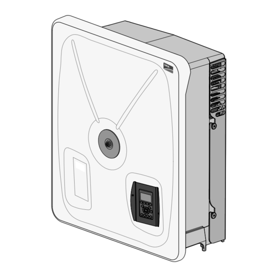
HINWEIS Home Back Alarm Schutzleiterprüfung vor Wiederinbetriebnahme Vor der Wiederinbetriebnahme von SMA Abbildung 1: Wechselrichter mit 2-teiligem Wechselrichtern nach Einbau von nicht intuitiv Gehäusedeckel zu tauschenden SMA Komponenten oder Der obere Teil des 2-teiligen Gehäusedeckels ist fest Leistungsbaugruppen sicherstellen, dass der montiert. -
Seite 59: Dc-Lasttrennschalter
SMA Solar Technology AG 3 Produktübersicht Der 1-teilige Gehäusedeckel ist mit einer Schraube Symbol Erklärung an einem darunter liegenden Zwischenrahmen mit Gefahr Traverse befestigt. Die Traverse stabilisiert die Dieses Symbol weist darauf hin, Verbindung zwischen Gehäuse, Zwischenrahmen dass der Wechselrichter und Gehäusedeckel. -
Seite 60: Typenschild Des Wechselrichters
Wechselrichters Das Typenschild identifziert den Wechselrichter eindeutig. Die Angaben auf dem Typenschild benötigen Sie für den sicheren Gebrauch des Produkts und bei Fragen an die SMA Service Line. Auf dem Typenschild fnden Sie folgende Informationen: • Gerätetyp (Model) • Seriennummer (Serial No.) •... -
Seite 61: Systemübersicht
Generatoranschlusskasten. Service des Wechselrichters über den SMA • SMA Inverter Manager Inverter Manager erforderlich. Das LCS-Tool Der SMA Inverter Manager ist für den Betrieb dient als primäre Benutzeroberfäche für die des Wechselrichters immer erforderlich. An PV-Anlage. jeden SMA Inverter Manager können bis zu 42... -
Seite 62: Auspacken
Das LCS-Tool muss auf einem lokalen Dichtungsmanschette für Ethernet-Kabel PC-Laufwerk installiert werden. Der PC muss mit 1 Erdungsbolzen M6 x 12 mm dem Anlagennetzwerk des SMA Inverter • Installationsanleitung Managers verbunden sein. Zur Einstellung über das LCS-Tool, siehe Kapitel 6.2, Seite 76. -
Seite 63: Umgebung Und Abstände
SMA Solar Technology AG 5 Installation 5.2 Umgebung und Abstände Abbildung 10: Gerade auf vertikaler Oberfäche einbauen. Eine Rückwärtsneigung von bis zu 10 Grad Abbildung 5: Ständigen Kontakt mit Wasser vermeiden ist zulässig. Abbildung 6: Direkte Sonneneinstrahlung vermeiden Abbildung 11: Staub und Ammoniakgase vermeiden... -
Seite 64: Montage Der Wandhalterung
5 Installation SMA Solar Technology AG 5.3 Montage der Wandhalterung Abbildung 12: Sicherheitsabstände in mm HINWEIS Die mitgelieferte Wandhalterung muss zwingend verwendet werden. Wird der Wechselrichter ohne Wandhalterung betrieben, erlischt der Garantieanspruch. Es wird dringend empfohlen, alle 6 Montagelöcher zu nutzen. -
Seite 65: Montage Des Wechselrichters
SMA Solar Technology AG 5 Installation • An der Frontseite des Wechselrichters zwecks sicherem Einbau und Servicezugang einen ausreichenden Abstand einhalten. Abbildung 15: Wechselrichter anheben 3. Die Position der Führungsschlitze an der Seite der Wandhalterung bestimmen. Abbildung 14: Befestigungspunkte (Schrauben und Dübel) 5.4 Montage des Wechselrichters... -
Seite 66: Demontage
5 Installation SMA Solar Technology AG 5. Sicherstellen, dass die vier seitlichen Schrauben sicher in den Führungsschlitzen der Wandhalterung sitzen. Beschädigung des Wechselrichters durch elektrostatische Entladung 6. Augenschrauben entfernen und zur Demontage aufbewahren. Durch das Berühren von elektronischen Bauteilen können Sie den Wechselrichter über 5.5 Demontage... -
Seite 67: Kabeleinführung
SMA Solar Technology AG 5 Installation 5.7 Kabeleinführung Die Montagehalterungen für die Kabelverschraubungen sind bereits vormontiert. 5. Alle 8 Befestigungsschrauben am Abbildung 18: AC-Kabelverschraubung Zwischenrahmen lösen (TX25). Installationsbereich bei 2-teiligem Gehäusedeckel öffnen 1. Wechselrichter freischalten. 2. An der Abdeckung des Installationsbereichs die 3 vorderen Schrauben lösen (TX30). -
Seite 68: Übersicht Des Installationsbereichs
5 Installation SMA Solar Technology AG Gerätetyp Leitermaterial Gerätetyp Durchmesser Kabelmantel mit mitgelieferter STP 60-10 Al/Cu Kabelverschraubung Al/Cu SHP 75-10 46 bis 53 mm 18 bis 25 mm STP 60-10 37 bis 44 mm 14 bis 21 mm 5.8 Übersicht des Installationsbereichs Abbildung 20: Anschlüsse im Installationsbereich... -
Seite 69: Ac-Anschluss
SMA Solar Technology AG 5 Installation 5.9 AC-Anschluss Kabelanforderungen SHP 75-10 IMI-Erkennung Der Wechselrichter verfügt über einen eingebauten Isolationswächter (IMI) und eine Fehlerstromüberwachungseinheit (RCMU). Der Wechselrichter reagiert auf Fehlergleichströme sowie auf plötzliche Veränderung im Erdschlussstrom. Diese Funktion ist bei Normalbetrieb aktiviert. -
Seite 70: Ethernet-Anschlüsse
5 Installation SMA Solar Technology AG 7. Alle Leiter müssen ordnungsgemäß mit dem HINWEIS richtigen Werkzeug (Bit - Länge min. 50 mm) und Für den AC-Anschluss können Kabel mit dem richtigen Drehmoment befestigt werden mehrdrähtigen, fein- oder feinstdrähtigen (siehe Kapitel 9.4, Seite 91). -
Seite 71: Pv-Anschluss
SMA Solar Technology AG 5 Installation 5.11.2 Kabelanforderungen Kabelanforderungen SHP 75-10 Abbildung 26: Kabelführung durch Kabelverschraubungen 5.11 PV-Anschluss 5.11.1 Externe Generatoranschlusskästen PV-Strings müssen über einen externen Generatoranschlusskasten an den DC-Eingang angeschlossen werden. Der Generatoranschlusskasten verbindet die PV-Strings des PV-Generators und schützt bei entsprechender Abbildung 27: DC-Aufkleber SHP 75-10... -
Seite 72: Pv Anschließen
5 Installation SMA Solar Technology AG 5.11.3 PV anschließen Die kombinierte Leistung aus dem Generatoranschlusskasten muss an den DC-Eingang des Wechselrichters angeschlossen werden. Die DC-Leistung kann mit dem DC-Lasttrennschalter Lebensgefahr durch Stromschlag beim im Wechselrichter getrennt werden. Berühren spannungsführender DC-Kabel Die PV-Module erzeugen bei Lichteinfall hohe Gleichspannung, die an den DC-Kabeln anliegt. -
Seite 73: Schließen
SMA Solar Technology AG 5 Installation 2. Die untere Kante des Gehäusedeckels am unteren Rand des Wechselrichters ansetzen. Dabei muss die Öffnung im Gehäusedeckel genau in der Schraube am Wechselrichter aufiegen. Abbildung 31: Kabel mit verschiedenen Leitern (von oben nach unten): mehrdrähtig, feindrähtig und feinstdrähtig... -
Seite 74: Ersteinrichtung Und Start
6 Ersteinrichtung und Start SMA Solar Technology AG 6 Ersteinrichtung und Start Wenn länger als ca. 10 Minuten nicht in das AC-Netz eingespeist wurde, trennt sich der Wechselrichter selbstständig vom Netz und schaltet 6.1 Benutzerschnittstelle sich ab. Die Benutzer- und... -
Seite 75: Display
Gerätetyp und Name des Wechselrichters Abbildung 32: Display mit Steuer- und Funktionstasten Seriennummer des Wechselrichters Display mit Steuer- und Funktionstasten IP-Adresse Taste Funktion Seriennummer des SMA Inverter Managers Anpassen der Kontraststufe Software-Version des Wechselrichters des Displays. Pfeil-nach-oben/unten-Taste 3. Ist-Werte. Dieser Abschnitt enthält: verwenden, solange die PV-Spannung und Strom F1-Taste gedrückt ist. -
Seite 76: Ersteinrichtung Über Lcs-Tool
Position I stellen. SMA bereitgestellt und über das LCS-Tool eingespielt STP 60-10 mit 2-teiligem Gehäusedeckel werden (siehe Installationsanleitung des SMA Inverter Manager / SMA Digital I/O Box / 1. Wechselrichter schließen (siehe LCS-Tool). Kapitel 5.12, Seite 73). 2. Den DC-Lasttrennschalter des Wechselrichters 6.3 DC-Lasttrennschalter... -
Seite 77: Freischalten
LCS-Tool aktivieren und konfgurieren. Für die „Zwischenkreis aktiv entladen“. Konfguration des übergeordneten Anlagenfallbacks 6. Installationsbereich öffnen (siehe zwischen dem SMA Inverter Manager und einer Kapitel 5.6, Seite 66). übergeordneten Regelungseinheit (z. B. 7. Spannungsfreiheit an der AC-Klemmleiste SCADA-System oder Power Plant Controller) siehe... -
Seite 78: Service
8 Service SMA Solar Technology AG 8 Service 8.1 Fehlersuche und -behebung Die Informationen werden in Tabellen aufgelistet und zeigen die Meldungen an, die im LCS-Tool erscheinen und als Ereignisse bekannt sind. Die Tabellen enthalten Beschreibungen von Ereignissen sowie Erklärungen, welche Maßnahmen im Falle von Ereignissen zu ergreifen sind. - Seite 79 SMA Solar Technology AG 8 Service Status- Beschreibung Maßnahme Hotline PV meldung 16 18 Der Wechselrichter hat Spannung und AC-Installation eine Spannungsspitze im überprüfen. Netz gemessen. 19, 22 Netzfrequenz zu niedrig Netzfrequenz überprüfen. oder zu hoch. 28 30 Netzfrequenzänderung Netzfrequenzabweichung überschritten.
- Seite 80 8 Service SMA Solar Technology AG Status- Beschreibung Maßnahme Hotline PV meldung Netzausfall, offene Phase Den zuständigen Netzbetreiber erkannt. kontaktieren, wenn das Ereignis mehrmals innerhalb eines Tages auftritt. Netzausfall. Den zuständigen Netzbetreiber kontaktieren, wenn das Ereignis mehrmals innerhalb eines Tages auftritt.
- Seite 81 SMA Solar Technology AG 8 Service Status- Beschreibung Maßnahme Hotline PV meldung 115, PV ISO zu Der Widerstand zwischen Sämtliche PV-Kabel und niedrig den PV-Strings und der Erde -Module per Sichtprüfung auf (PE) ist für die korrekte Installation gemäß Inbetriebnahme des Installationsanleitung prüfen.
- Seite 82 8 Service SMA Solar Technology AG Systembezogene Ereignisse Statusme Beschreibung Maßnahme ldung Hotline 2000 Kommunikationsbaugrupp e fährt hoch. 2010, Das Software-Update des 2011 Hauptrechners wurde gestartet / ist beendet. 2012 - Das Software-Update ist Software-Update erneut 2018 fehlgeschlagen. beginnen. Falls Fehler beim Update auftreten, kontaktieren Sie den Service.
- Seite 83 SMA Solar Technology AG 8 Service Statusme Beschreibung Maßnahme ldung Hotline 2056 Fallback Der Wechselrichter ist beendet wieder in den Normalbetrieb übergegangen, nachdem er sich aufgrund einer Kommunikationsstörung mit dem SMA Inverter Manager im Fallback-Modus befand. Interne Ereignisse Statusme Beschreibung Maßnahme...
- Seite 84 8 Service SMA Solar Technology AG Statusme Beschreibung Maßnahme ldung Hotline Störung im Speicher/ Wechselrichter neu starten. 240, EEPROM. Wenn das Ereignis andauert, den Service kontaktieren. 241, Interner Wechselrichter neu starten. 242, Kommunikationsfehler. Wenn das Ereignis andauert, 245, den Service kontaktieren.
- Seite 85 SMA Solar Technology AG 8 Service Statusme Beschreibung Maßnahme ldung Hotline Grid-Code-Einstellungen Wechselrichter neu starten. ungültig. Wenn der Fehler weiterhin auftritt, bitten Sie die Serviceabteilung um die Erstellung einer neuen Grid-Code-Datei bzw. die erneute Auswahl eines Standard-Grid-Codes. Gatedrive-Fehler. Wechselrichter neu starten.
-
Seite 86: Wartung
8 Service SMA Solar Technology AG Beschreibung Maßnahme VNB Hotline AC-Überspannungsschutzgerät-Fehl AC-Überspannungsschutzgerät er. Wechselrichter läuft weiter ohne austauschen. Details entnehmen Sie Überspannungsschutz. den Anweisungen zum SPD-Austausch. Status des Wechselrichter neu starten. Wenn Überspannungsschutzgerätes das Ereignis andauert, den Service unbekannt. kontaktieren. -
Seite 87: Technische Daten
SMA Solar Technology AG 9 Technische Daten 9 Technische Daten 9.1 Spezifkationen Parameter SHP 75-10 STP 60-10 Nenn-Scheinleistung 75000 VA 60000 VA Nenn-Wirkleistung 75000 W 60000 W Blindleistungsbereich 0 bis 75000 var 0 bis 60000 var AC-Nennspannung 3 / PE; 400 V (50 Hz) 3 / PE;... - Seite 88 9 Technische Daten SMA Solar Technology AG Parameter SHP 75-10 STP 60-10 Anzahl der unabhängigen 1 / 1 (Aufteilung durch externen 1 / 1 (Aufteilung durch externen MPP-Eingänge / Generatoranschlusskasten) Generatoranschlusskasten) Strings pro MPP-Eingang Überspannungskategorien AC: Überspannungskategorie III AC: Überspannungskategorie III...
-
Seite 89: Konformität
SMA Solar Technology AG 9 Technische Daten Parameter SHP 75-10 STP 60-10 Funktionale Sicherheit • Spannungs- und • Spannungs- und Frequenzüberwachung Frequenzüberwachung • Überwachung des • Überwachung des Gleichstromanteils im Gleichstromanteils im Wechselstrom Wechselstrom • Überwachung des • Überwachung des... -
Seite 90: Installationsbedingungen
Gerade auf vertikaler Oberfäche einbauen. Staub und Ammoniakgase vermeiden. * Mögliche Leistungsreduzierung über 45 °C (für weitere Informationen siehe Technische Information „Wirkungsgrade und Derating“) ** Aufstellung in Höhen > 2000 m sind auf Anfrage möglich, hierzu SMA Solar Technology AG kontaktieren. SHP75-10-STP60-10-IA-xx-19 Installationsanleitung... -
Seite 91: Drehmomentspezifkationen
SMA Solar Technology AG 9 Technische Daten 9.4 Drehmomentspezifkationen Abbildung 33: Überblick über Wechselrichter mit Drehmomentvorgaben Anzugsdrehmomente SHP 75-10 Parameter Werkzeug Anzugsdrehmoment M63-Kabelverschraubung Schraubenschlüssel 65/68 11 Nm Überwurfmutter für Schraubenschlüssel 65/68 9,5 Nm M63-Kabelverschraubung AC-Anschlussklemmen HX 8 x 50 20 Nm (Leiterquerschnitt = 35 mm²... -
Seite 92: Spezifkation Für Die Netzsicherungen
9 Technische Daten SMA Solar Technology AG Anzugsdrehmomente STP 60-10 Parameter Werkzeug Anzugsdrehmoment M63-Kabelverschraubung Schraubenschlüssel 65/68 6 Nm Überwurfmutter für Schraubenschlüssel 65/68 3 Nm M63-Kabelverschraubung Klemmen am AC-Anschluss TX 30 x 50 14 Nm (Leiterquerschnitt = 35 mm² bis 95 mm²) Primärer Schutzleiter (sekundärer... -
Seite 93: Technische Daten Der Kommunikationsschnittstellen
Über RJ45-Stecker Galvanische Ja, 500 Veff Schnittstellentrennung Direkter Berührungsschutz Doppelte/verstärkte Isolierung Kurzschlussschutz Kommunikation Netzwerktopologie Stern-, Ring- und verkettete Verbindung Kabel Max. Kabellänge zwischen 100 m Wechselrichtern Max. Anzahl der Pro SMA Inverter Manager 42 Wechselrichter siehe Kapitel 5.10 „Ethernet-Anschlüsse“, Seite 70 Installationsanleitung SHP75-10-STP60-10-IA-xx-19... -
Seite 94: Ethernet-Anschlüsse
9 Technische Daten SMA Solar Technology AG 9.7 Ethernet-Anschlüsse HINWEIS Ringtopologie (C ) ist nur zulässig, wenn sie mit einem Ethernet-Switch realisiert wird, der das Spanning-Tree-Protokoll unterstützt. Abbildung 34: Pinbelegung des RJ45-Steckers für Ethernet Pinbelegun Farbstandard g Ethernet Cat. 5 Cat. 5... -
Seite 95: Kontakt
Blinkt Aktivität 10 Kontakt Bei technischen Problemen mit unseren Produkten wenden Sie sich an die SMA Service Line. Wir benötigen folgende Daten, um Ihnen gezielt helfen zu können: • Gerätetyp des Wechselrichters • Seriennummer des Wechselrichters • Firmware-Version des Wechselrichters •... -
Seite 96: Disposiciones Legales
Disposiciones legales 1 Indicaciones sobre el documento SMA Solar Technology AG es propietaria de todos los derechos de la información que se facilita en esta documentación. Queda prohibida la reproducción total o parcial de este documento, así 1.1 Área de validez como su almacenamiento en un sistema de recuperación y toda... -
Seite 97: Símbolos Del Documento
SMA Solar Technology AG 1 Indicaciones sobre el documento Abreviatu Descripción Símbolo Explicación Advertencia que, de no ser DHCP Protocolo para transmitir direcciones IP observada, puede causar dinámicas (Dynamic Host lesiones físicas leves o de Confguration Protocol): permite gravedad media... -
Seite 98: Información Adicional
Resistencia del aislamiento (insulation • Instrucciones de instalación del resistance) SMA Inverter Manager y de la I/O Box: ofrece ROCOF Tasa de variación de la frecuencia información para la puesta en marcha y la (Rate Of Change Of Frequency) confguración de la comunicación. -
Seite 99: Seguridad
SMA Solar Technology AG 2 Seguridad 2 Seguridad de SMA Solar Technology AG. Los cambios no autorizados conllevan la plrdida de los derechos de garantía, así como la extinción de la autorización de 2.1 Uso previsto operación. Queda excluida la responsabilidad de El Sunny Tripower es un inversor fotovoltaico sin SMA Solar Technology AG por los daños derivados... - Seite 100 2 Seguridad SMA Solar Technology AG Peligro de muerte por descarga eléctrica por Peligro de muerte por descarga eléctrica si se contacto con componentes conductores de tocan partes de la planta bajo tensión en caso tensión o cables del inversor...
- Seite 101 SMA Solar Technology AG 2 Seguridad Peligro de muerte por fuego y explosión Peligro de lesiones por sustancias tóxicas, gases y polvos. En infrecuentes casos aislados, puede producirse en caso de error una mezcla de gas infamable en En algunos casos aislados, en el interior del el interior del inversor.
- Seite 102 Daños en el inversor por descarga Antes de la nueva puesta en marcha de los electrostática inversores de SMA despuls de instalar Si toca componentes electrónicos, puede dañar o componentes de SMA o subgrupos de destruir el inversor debido a una descarga potencia que no se puedan sustituir de forma electrostática.
-
Seite 103: Vista General Del Producto
SMA Solar Technology AG 3 Vista general del producto 3 Vista general del producto 3.2 Interruptor-seccionador de potencia de CC 3.1 Vista frontal del inversor Home Back Alarm Imagen 3: Interruptor-seccionador de potencia de CC Interruptor-seccionador de potencia de CC Imagen 1: Inversor con tapa de la carcasa de dos piezas La parte superior de la tapa de la carcasa de dos INDICACIÓN... -
Seite 104: Placa De Características Del Inversor
En los componentes conductores forma segura y a responder a las preguntas del del inversor existen altas tensiones Servicio Tlcnico de SMA. En la placa de que pueden causar descargas características encontrará esta información: ellctricas mortales. -
Seite 105: Vista General Del Sistema
• SMA Inverter Manager fotovoltaica. El SMA Inverter Manager siempre es necesario para gestionar el inversor. A cada SMA Inverter Manager pueden conectarse hasta Guía de instalación SHP75-10-STP60-10-IA-xx-19... -
Seite 106: Desembalaje
El ordenador tiene que estar 1 perno de puesta a tierra M6 x 12 mm conectado a la red de la planta del SMA Inverter • Instrucciones de instalación Manager. Si desea realizar la confguración mediante la LCS-Tool, consulte capítulo 6.2,... -
Seite 107: Entorno Y Espacios Libres
SMA Solar Technology AG 5 Instalación 5.2 Entorno y espacios libres Imagen 10: Montaje recto en una superfcie vertical Se permite una inclinación hacia atrás de hasta Imagen 5: Evite el fujo constante de agua 10º. Imagen 6: Evite la irradiación solar directa Imagen 11: Evite la exposición a polvo y gases de... -
Seite 108: Montaje Del Soporte Mural
5 Instalación SMA Solar Technology AG 5.3 Montaje del soporte mural Imagen 12: Espacios de seguridad en mm INDICACIÓN Es obligatorio utilizar la placa de montaje suministrada con el inversor. Si el inversor opera sin el soporte mural, la garantía no tiene validez. -
Seite 109: Montaje Del Inversor
SMA Solar Technology AG 5 Instalación • Compruebe que dispone del espacio libre adecuado en la parte delantera para acceder al inversor con seguridad durante las tareas de instalación y mantenimiento. Imagen 15: Levante el inversor 3. Coloque las ranuras en el lateral de la placa de montaje. -
Seite 110: Desmontaje
5 Instalación SMA Solar Technology AG 6. Retire las armellas y guárdelas para el desmontaje. Daños en el inversor por descarga 5.5 Desmontaje electrostática Procedimiento: Si toca componentes electrónicos, puede dañar o destruir el inversor debido a una descarga 1. Utilice las armellas M12 y tuercas compatibles electrostática. -
Seite 111: Entrada De Cables
SMA Solar Technology AG 5 Instalación 5.7 Entrada de cables Los soportes de montaje para los racores atornillados para cables están ya premontados. 5. Afoje los 8 tornillos de fjación del marco Imagen 18: Racor atornillado para cables de CA intermedio (TX25). -
Seite 112: Vista General Del Área De Instalación
5 Instalación SMA Solar Technology AG Modelo Material de los conductores Modelo Diámetro del revestimiento del cable con los racores atornillados SHP 75-10 Al/Cu para cables suministrados Al/Cu SHP 75-10 46 a 53 mm STP 60-10 Al/Cu 18 a 25 mm... -
Seite 113: Conexión De Ca
SMA Solar Technology AG 5 Instalación Renuisitos del cableado SHP 75-10 5.9 Conexión de CA Detección IMI El inversor cuenta con un controlador de aislamiento integrado (IMI) y una unidad de control de corriente de defecto (RCMU). El inversor reacciona a corrientes continuas de defecto y a una variación... -
Seite 114: Conexiones De Ethernet
5 Instalación SMA Solar Technology AG 7. Todos los conductores deben apretarse INDICACIÓN adecuadamente y con la herramienta apta Para la conexión de CA se pueden utilizar (broca - longitud mín. de 50 mm) y el par de cables con conductores de varios hilos, de hilo apriete correcto (consulte capítulo 9.4,... -
Seite 115: Conexión Fotovoltaica
SMA Solar Technology AG 5 Instalación 5.11.2 Renuisitos para el cableado Renuisitos del cableado SHP 75-10 Imagen 26: Recorrido de los cables a travls de los racores atornillados para cables 5.11 Conexión fotovoltaica 5.11.1 Cajas de conexión del generador externas Los strings deben conectarse a la entrada de CC a travls de una caja de conexión del generador... -
Seite 116: Conexión Fotovoltaica
5 Instalación SMA Solar Technology AG 5.11.3 Conexión fotovoltaica La salida de la caja de conexión del generador debe conectarse a la entrada de CC del inversor. La potencia de CC se puede desconectar por medio del interruptor-seccionador de potencia de CC Peligro de muerte por descarga eléctrica por... -
Seite 117: Cierre
SMA Solar Technology AG 5 Instalación 2. Coloque el canto inferior de la tapa de la carcasa en el borde inferior del inversor La abertura de la tapa de la carcasa debe situarse exactamente en el tornillo del inversor. Imagen 31: Cables con diferentes tipos de conductores (de... -
Seite 118: Confguración Inicial Y Arrannue
6 Confguración inicial y arranque SMA Solar Technology AG 6 Confguración inicial y Si no se ha suministrado potencia a la red de CA durante más de 10 minutos aproximadamente, el arrannue inversor se desconecta de la red y se apaga. Las interfaces de usuario y comunicación permanecen... -
Seite 119: Pantalla
Número de serie del inversor Imagen 3.1. Pantalla con botones de control y funcionamiento Dirección IP Información general sobre los botones y las Número de serie del SMA Inverter Manager funciones de la pantalla Tecla Función Versión de software del inversor Ajustar el nivel de contraste 3. -
Seite 120: Ajuste Inicial Mediante Lcs-Tool
LCS-Tool (vlase las STP 60-10 con tapa de la carcasa de dos piezas instrucciones de instalación del 1. Cierre el inversor ((consulte el capítulo 5.12, SMA Inverter Manager / SMA Digital I/O Box / página 117)). LCS-Tool). 2. Coloque el interruptor-seccionador de potencia 6.3 Conecte el... -
Seite 121: Desconexión
5. Espere 60 minutos antes de abrir la tapa de la procedimiento de emergencia superior de la carcasa. Para el SHP 75-10 es posible instalación entre el SMA Inverter Manager y una descargar de forma activa el circuito intermedio unidad de regulación superior (p. ej. sistema SCADA pasados 10 minutos. - Seite 122 7 Desconexión SMA Solar Technology AG 5. Coloque el interruptor-seccionador de potencia de CC en la posición O y asegúrelo contra reconexiones. 6. Abra el área de instalación ((consulte el capítulo 5.6, página 110)). 7. Compruebe sucesivamente con un equipo de medición adecuado que no haya tensión en la caja de bornes de CA entre L1 y PE, L2 y PE, L3 y PE, L1 y L2, L2 y L3 y L1 y L3.
-
Seite 123: Mantenimiento
SMA Solar Technology AG 8 Mantenimiento 8 Mantenimiento 8.1 Resolución de problemas La información se organiza en tablas donde se pueden ver los mensajes que aparecen en la LCS-Tool, conocidos como incidencias. Las tablas contienen descripciones de incidencias, así como explicaciones de las acciones que se deben llevar a cabo cuando se produce una. - Seite 124 8 Mantenimiento SMA Solar Technology AG Aviso Descripción Medida Servici estado Técnic distr o de ibui La tensión media de la red Compruebe que la instalación durante 10 minutos es sea correcta según la guía de demasiado alta. instalación. En caso afrmativo, pida un nuevo archivo del código de red con un límite de...
- Seite 125 SMA Solar Technology AG 8 Mantenimiento Aviso Descripción Medida Servici estado Técnic distr o de ibui 41 43 Fault ride through. El Si esta incidencia se produce inversor ha detectado que varias veces al día, realice un la tensión de red era análisis de red in situ.
- Seite 126 8 Mantenimiento SMA Solar Technology AG Incidencias relacionadas con la energía fotovoltaica Aviso Descripción Medida Servici estado Técnic distr o de ibui PV current Existen demasiados Compruebe el número de is too módulos fotovoltaicos cadenas en paralelo y las high/ conectados en paralelo.
- Seite 127 SMA Solar Technology AG 8 Mantenimiento Aviso Descripción Medida Servici estado Técnic distr o de ibui PV voltage La tensión de CC es Compruebe que la instalación y too high/ demasiado elevada. la disposición fotovoltaica waiting corresponden a las recomendaciones de los manuales.
- Seite 128 Este error sirve para identifcar, por ejemplo, un cable de ethernet averiado. 2052, La transmisión del código 2053 de red del SMA Inverter Manager al inversor se ha iniciado/terminado. 2054 La transmisión del código Si esta incidencia se muestra a de red del SMA Inverter menudo, póngase en contacto...
- Seite 129 SMA Solar Technology AG 8 Mantenimiento Aviso de Descripción Medida Servici estado Técnic distr o de ibui 2055 Procedimi El inversor pasa al modo de ento de procedimiento de emergenci emergencia una vez se ha a activado interrumpido la comunicación con el SMA Inverter Manager.
- Seite 130 8 Mantenimiento SMA Solar Technology AG Incidencias internas Aviso de Descripción Medida Servici estado Técnic distr o de ibui La temperatura interna del Compruebe que el inversor no inversor es demasiado está cubierto y que el tubo de elevada. ventilación no está bloqueado.
- Seite 131 SMA Solar Technology AG 8 Mantenimiento Aviso de Descripción Medida Servici estado Técnic distr o de ibui La corriente medida en el Si la incidencia persiste, lado de CA es demasiado póngase en contacto con el elevada. servicio tlcnico. 243, Error interno.
- Seite 132 8 Mantenimiento SMA Solar Technology AG Aviso de Descripción Medida Servici estado Técnic distr o de ibui Error del ventilador interno. Si la incidencia persiste, Se ha reducido la potencia póngase en contacto con el de salida máxima. servicio tlcnico.
- Seite 133 SMA Solar Technology AG 8 Mantenimiento Descripción Medida Servicio rado Tlcnico distri buid Error del descargador de Sustituya el descargador de sobretensiones de fotovoltaica. El sobretensiones de fotovoltaica. inversor seguirá funcionamiento sin Encontrará información más protección contra sobretensión. detallada en las instrucciones para cambiar los descargadores contra sobretensión.
-
Seite 134: Mantenimiento
8 Mantenimiento SMA Solar Technology AG 8.2 Mantenimiento Peligro de nuemaduras debido a componentes calientes Algunos componentes (como disipadores de calor) del interior del inversor pueden calentarse durante el funcionamiento. Si se tocan los componentes calientes, pueden producirse quemaduras. • Monte el inversor de tal manera que difculte el contacto con las partes calientes. -
Seite 135: Datos Técnicos
SMA Solar Technology AG 9 Datos tlcnicos 9 Datos técnicos 9.1 Especifcaciones Parámetro SHP 75-10 STP 60-10 Potencia aparente nominal 75000 VA 60000 VA Potencia activa nominal 75000 W 60000 W Intervalo de potencia reactiva De 0 a 75000 var De 0 a 60000 var Tensión nominal de CA... - Seite 136 9 Datos tlcnicos SMA Solar Technology AG Parámetro SHP 75-10 STP 60-10 Número de entradas de MPP 1/1 (distribución por cajas de 1/1 (distribución por cajas de independientes/ conexión del generador externas) conexión del generador externas) Strings por entrada de MPP Categorías de sobretensión...
-
Seite 137: Conformidad
SMA Solar Technology AG 9 Datos tlcnicos Parámetro SHP 75-10 STP 60-10 Seguridad funcional • Monitorización de tensión y • Monitorización de tensión y frecuencia frecuencia • Monitorización del contenido • Monitorización del contenido CC de la corriente alterna (CA) CC de la corriente alterna (CA) •... -
Seite 138: Condiciones De La Instalación
1 Posible reducción de potencia por encima de 45 °C (para obtener más información, consulte la información tlcnica “Rendimiento y derrateo”) 2 Instalaciones en altitudes > 2000 m son posibles a petición del cliente; póngase en contacto con SMA Solar Technology AG. SHP75-10-STP60-10-IA-xx-19... -
Seite 139: Especifcaciones Del Par De Apriete
SMA Solar Technology AG 9 Datos tlcnicos 9.4 Especifcaciones del par de apriete Imagen 32: Vista general del inversor con indicaciones del par de apriete Pares de apriete SHP 75-10 Parámetro Herramienta Par de apriete Racor atornillado para cables Llave 65/68 mm 11 Nm Tuerca de unión para racores... -
Seite 140: Especifcaciones Del Circuito De La Red Ellctrica
9 Datos tlcnicos SMA Solar Technology AG Parámetro Herramienta Par de apriete Tornillo frontal (no se muestra) TX 30 1,5 Nm Pares de apriete STP 60-10 Parámetro Herramienta Par de apriete Racor atornillado para cables Llave 65/68 mm 6 Nm Tuerca de unión para racores... -
Seite 141: Especifcaciones De Las Interfaces De Comunicación
Topología de red Conexión en estrella, en anillo y en cadena Cable Longitud máxima de 100 m cableado entre inversores Número máx. de inversores Por SMA Inverter Manager 42 (consulte el capítulo 5.10 “Conexiones de ethernet”, página 114) Guía de instalación SHP75-10-STP60-10-IA-xx-19... -
Seite 142: Conexiones De Ethernet
9 Datos tlcnicos SMA Solar Technology AG 9.7 Conexiones de ethernet INDICACIÓN La topología de anillo (C) solo está permitida si se hace con árbol de expansión compatible y conmutador de ethernet. Imagen 33: Datos del diagrama de pines del conector... -
Seite 143: Contacto
10 Contacto Si surge algún problema tlcnico con nuestros productos, póngase en contacto con el Servicio Tlcnico de SMA. Para ayudarle de forma efcaz, necesitamos que nos facilite estos datos: • Modelo del inversor • Número de serie del inversor •... -
Seite 144: Disposizioni Legali
Si comunica tuttavia espressamente ai lettori • Corso di formazione su pericoli e rischi durante che SMA Solar Technology AG si riserva il diritto, senza preavviso l’installazione, la riparazione e l’uso di e/o in conformità alle corrispondenti disposizioni del contratto di... -
Seite 145: Denominazioni Nel Documento
SMA Solar Technology AG 1 Note relative al documento 1.7 Abbreviazioni Simbolo Spiegazione Avvertenza di sicurezza la Abbrevia Descrizione cui inosservanza può zione provocare lesioni gravi o cat5e Cavo di categoria 5 (caratteristiche mortali migliorate) con doppini ritorti Avvertenza di sicurezza la (Twisted-Pair) per la trasmissione di dati cui inosservanza può... -
Seite 146: Ulteriori Informazioni
Il punto al quale il sistema FV viene • Istruzioni per l’installazione di collegato alla rete pubblica. SMA Inverter Manager e I/O Box: contiene Potenza [W] in condizioni di prova informazioni per la messa in servizio nonchl per standard la confgurazione della comunicazione. -
Seite 147: Avvertenze Di Sicurezza Importanti
Il contatto con provocare danni personali o materiali. componenti sotto tensione o cavi dell'inverter può Interventi sui prodotti SMA come ad es. modifche o determinare la morte o lesioni mortali per trasformazioni sono consentiti solo previa folgorazione. - Seite 148 2 Sicurezza SMA Solar Technology AG Pericolo di morte per incendio ed esplosione Pericolo di morte per folgorazione in caso di contatto con parti dell'impianto sotto tensione in In rari casi in presenza di un guasto può crearsi una presenza di una dispersione verso terra miscela di gas infammabile all’interno dell’inverter.
- Seite 149 Verifca del conduttore di protezione prima della rimessa in funzione Prima di rimettere in funzione gli inverter SMA dopo il montaggio di componenti o gruppi di Danneggiamento dell’inverter per scarica potenza SMA la cui sostituzione non è intuitiva,...
-
Seite 150: Panoramica Del Prodotto
SMA Solar Technology AG NOTA Rispettare gli standard di livello superiore Prima di rimettere in funzione gli inverter SMA dopo il montaggio di componenti o gruppi di potenza SMA la cui sostituzione non è intuitiva, accertarsi che il conduttore di protezione sia collegato correttamente nell'inverter. -
Seite 151: Simboli Sull'inverter
Servizio di assistenza tecnica SMA. Sulla targhetta di Nei componenti dell’inverter identifcazione si trovano le seguenti informazioni: percorsi da corrente sono presenti •... -
Seite 152: Panoramica Del Sistema
3 Panoramica del prodotto SMA Solar Technology AG 3.5 Panoramica del sistema a 42 inverter. SMA Inverter Manager gestisce Figura 4: Panoramica del sistema l’intera comunicazione degli inverter. Funge da L’impianto FV è composto da 4 componenti interfaccia dell’impianto per sistemi di... -
Seite 153: Disimballaggio
6 viti di montaggio, 6 x 60 mm del PC. Il PC deve essere collegato alla rete 1 passacavo M25 con pressacavo con dell’impianto di SMA Inverter Manager. Per le guarnizione per cavi Ethernet impostazioni tramite LCS Tool, v.cap. 6.2, 1 bullone M6 x 12 mm pag. 166. - Seite 154 5 Installazione SMA Solar Technology AG Figura 6: Evitare l’esposizione diretta all’irraggiamento Figura 11: Prevenire la polvere e i gas ammoniacali solare NOTA Nella scelta del luogo di installazione, assicurarsi che le etichette del prodotto e di avvertenza dell’inverter rimangano sempre visibili. Per informazioni dettagliate a proposito vedere cap.
-
Seite 155: Installazione
SMA Solar Technology AG 5 Installazione 5.3 Montaggio del supporto da parete Figura 12: Distanze di sicurezza in mm NOTA L’utilizzo del supporto da parete fornito insieme all’inverter è obbligatorio. Se l’inverter viene messo in servizio senza il supporto da parete, la garanzia decade. -
Seite 156: Montaggio Dell'inverter
5 Installazione SMA Solar Technology AG Figura 14: Punti di fssaggio (viti e tasselli) Figura 15: Sollevare l'inverter 3. Localizzare la posizione degli alloggiamenti sul 5.4 Montaggio dell’inverter lato del supporto da parete. Pericolo di lesioni a causa del peso del prodotto... -
Seite 157: Smontaggio
SMA Solar Technology AG 5 Installazione 5.5 Smontaggio Aprire l'area di installazione in presenza del coperchio dell'involucro singolo: Procedura: 1. Disinserire l’inverter. 1. Fissare all’inverter le viti ad occhiello M12 e i 2. Allentare la vite collocata al centro del coperchio dadi compatibili (non compresi nel contenuto dell'involucro singolo dell'inverter (TX55). -
Seite 158: Introduzione Dei Cavi
5 Installazione SMA Solar Technology AG Aprire l'area di installazione in presenza del coperchio dell'involucro doppio: 1. Disinserire l’inverter. 2. Allentare le 3 viti anteriori sul coperchio dell'area di installazione (TX30). Le viti sono viti prigioniere e non possono cadere. -
Seite 159: Panoramica Dell'area Di Installazione
SMA Solar Technology AG 5 Installazione 5.8 Panoramica dell'area di installazione 5.9 Collegamento CA Figura 20: Collegamenti nell'area di installazione Riconoscimento IMI PELV (protezione contro le scariche elettriche) L’inverter è dotato di un dispositivo di monitoraggio Messa a terra del dispositivo dell’isolamento (IMI) integrato e di un’unità... - Seite 160 5 Installazione SMA Solar Technology AG nuovamente la resistenza dopo un breve lasso di Renuisiti dei cavi STP 60-10 tempo. Quando la resistenza è sopra il valore impostato dal codice di rete, l’inverter effettua un test automatico e si collega alla rete pubblica.
-
Seite 161: Collegamenti Ethernet
SMA Solar Technology AG 5 Installazione Sul cavo CA, spelare tutti e 4 i fli. Il conduttore di dentro l’involucro dell’inverter. Questo serve a protezione (PE) deve essere pii lungo dei conduttori proteggere i connettori Ethernet RJ45 montati su di rete. -
Seite 162: Requisiti Dei Cavi
5 Installazione SMA Solar Technology AG Renuisiti dei cavi STP 60-10 NOTA Osservare i valori nominali corretti dei fusibili! Consultare i manuali dei produttori del modulo per informazioni sui valori nominali corretti dei fusibili delle stringhe. NOTA Usare un voltmetro adeguato in grado di misurare fno a 1000 V CC. - Seite 163 SMA Solar Technology AG 5 Installazione Pericolo di morte a causa di arco voltaico in caso di collegamento a polarità inversa del cavo CC In caso di collegamento a polarità inversa del cavo CC può generarsi un arco voltaico. In caso di formazione di un arco voltaico, sussiste il rischio di morte o di gravi lesioni.
-
Seite 164: Chiudi
6 Setup iniziale e avviamento SMA Solar Technology AG 5.12 Chiudi Chiudere l'inverter con coperchio dell'involucro singolo: 1. Inserire il telaio intermedio nell'inverter e serrare le 8 viti di fssaggio (TX25, coppia: 6 Nm). Chiudere l'inverter con coperchio dell'involucro doppio: 1. -
Seite 165: Display
SMA Solar Technology AG 6 Setup iniziale e avviamento • La potenza FV è insufciente (nessuna Stato immissione in rete per 10 minuti circa). Off grid (Non Verde Internal inverter event (LED verde lampeggiante) connesso alla rete Rosso pubblica) L’inverter è in attesa di una condizione interna per... -
Seite 166: Setup Iniziale Attraverso Lcs Tool
Passa alla schermata a record di dati nazionali per diverse reti. I record di sinistra dati nazionali specifci per il cliente possono essere predisposti da SMA e caricati tramite LCS Tool (v. Back Torna alla schermata istruzioni per l’installazione di... -
Seite 167: Inserimento Del Sezionatore Cc
6.4 Messa in servizio 6.6 Confgurazione del fallback L’inverter si avvia automaticamente se è disponibile Se la comunicazione fra inverter ed SMA Inverter un’irradiazione solare sufciente L'avvio richiede Manager viene interrotta, l’inverter passa in una alcuni minuti. Durante questo periodo, l’inverter condizione di funzionamento precedentemente effettua un autotest. -
Seite 168: Disinserire
7 Disinserire SMA Solar Technology AG MK104 oppure sul contatto destro del fusibile Parametro Range di valori F200 ( + ) e sul collegamento destro della impostabili bobina L201 ( - ) fno a quando verrà Reazione P 0 a 100% visualizzato un valore che tende a 0 V. -
Seite 169: Assistenza
SMA Solar Technology AG 8 Assistenza 8 Assistenza 8.1 Ricerca degli errori Le informazioni sono organizzate in tabelle che mostrano i messaggi visualizzati in LCS Tool, noti come eventi. Le tabelle contengono descrizioni di eventi nonchl spiegazioni di quali azioni intraprendere quando si verifca un determinato evento. - Seite 170 8 Assistenza SMA Solar Technology AG Messagg Descrizione Provvedimento Servizi o di di stato assiste tecnica Media della tensione di Controllare che l’installazione rete troppo elevata per 10 sia corretta in base alla guida minuti. all’installazione. In tal caso, richiedere un nuovo fle del...
- Seite 171 SMA Solar Technology AG 8 Assistenza Messagg Descrizione Provvedimento Servizi o di di stato assiste tecnica 48, 51 Frequenza di rete troppo Controllare la frequenza e bassa o troppo elevata. l’installazione CA. 54 56 Corrente di rete CC troppo Per occorrenze giornaliere elevata (fase 2).
- Seite 172 8 Assistenza SMA Solar Technology AG Eventi FV Messagg Descrizione Provvedimento Servizi o di di stato assiste tecnica Troppi moduli FV collegati Controllare il numero di stringhe corrente in parallelo. Dovrebbe in parallelo e i valori nominali FV è apparire soltanto su della corrente.
- Seite 173 SMA Solar Technology AG 8 Assistenza Messagg Descrizione Provvedimento Servizi o di di stato assiste tecnica Avvertenza tensione CC Controllare che l’impianto FV e elevata. la confgurazione corrispondano alle raccomandazioni nei manuali. Troppi moduli FV collegati Controllare il numero di stringhe corrente in parallelo.
- Seite 174 Questo errore consente ad es. di identifcare cavi Ethernet guasti. 2052, La trasmissione del codice 2053 di rete di SMA Inverter Manager all’inverter è stato avviato/concluso. 2054 La trasmissione del codice Se questo evento si verifca di rete di SMA Inverter frequentemente, contattare il Manager all’inverter non è...
- Seite 175 SMA Solar Technology AG 8 Assistenza Segnalaz Descrizione Provvedimento Servizi ione di o di stato assiste tecnica 2055 Fallback L’inverter è passato alla attivato modalità di fallback dopo l’interruzione della comunicazione con SMA Inverter Manager. 2056 Fallback L’inverter è ritornato alla...
- Seite 176 8 Assistenza SMA Solar Technology AG Eventi interni Segnalaz Descrizione Provvedimento Servizi ione di o di stato assiste tecnica La temperatura interna Controllare che l’inverter non dell’inverter è troppo sia coperto da oggetti o polvere elevata. e che i canali di aerazione non siano ostruiti o intasati.
- Seite 177 SMA Solar Technology AG 8 Assistenza Segnalaz Descrizione Provvedimento Servizi ione di o di stato assiste tecnica 243, Errore interno. Riavviare l’inverter. Se l’evento persiste, chiamare l’assistenza. Errore del sensore di Se l’evento persiste, chiamare temperatura l’assistenza. Timeout autotest 24 ore.
- Seite 178 8 Assistenza SMA Solar Technology AG Eventi causati dall’autotest Descrizione Provvedimento VNB Servizio assisten tecnica La corrente di ingresso FV è Controllare la polarità negativa. Errore del sensore. dell’installazione FV. Se è corretta, chiamare il ervizio di assistenza tecnica. Test del circuito di misura fallito.
-
Seite 179: Manutenzione
SMA Solar Technology AG 8 Assistenza Descrizione Provvedimento VNB Servizio assisten tecnica Il test del transistor e dei relè è fallito Avvertenza: non attivare il oppure si è guastato il relè sezionatore di carico CC dell’inverter (con la premessa che il dell'inverter. -
Seite 180: Dati Tecnici
9 Dati tecnici SMA Solar Technology AG 9 Dati tecnici 9.1 Specifche Parametro SHP 75-10 STP 60-10 Potenza apparente nominale 75000 VA 60000 VA Potenza attiva nominale 75000 W 60000 W Range di potenza reattiva 0 ... 75000 VAr 0 ... 60000 VAr Tensione nominale CA 3 / PE;... - Seite 181 SMA Solar Technology AG 9 Dati tecnici Parametro SHP 75-10 STP 60-10 Numero di ingressi MPP 1/1 (suddivisione mediante 1/1 (suddivisione mediante indipendenti / stringhe per cassette di collegamento cassette di collegamento ingresso MPP generatore esterne) generatore esterne) Categorie di sovratensione...
- Seite 182 9 Dati tecnici SMA Solar Technology AG Parametro SHP 75-10 STP 60-10 Sicurezza funzionale • Monitoraggio di tensione e • Monitoraggio di tensione e frequenza frequenza • Monitoraggio della quota di • Monitoraggio della quota di corrente continua nella corrente...
-
Seite 183: Conformità
SMA Solar Technology AG 9 Dati tecnici 9.2 Conformità Norme internazionali SHP 75-10 STP 60-10 Grado di rendimento Massimo grado di rendimento, Massimo grado di rendimento, standard: EN 50530 standard: EN 50530 Direttiva CE sulla bassa 2014/35/EU 2014/35/EU tensione Direttiva CE sulla compatibilità... -
Seite 184: Condizioni Di Installazione
* Possibile riduzione della potenza oltre i 45 °C (per maggiori informazioni v. informazione tecnica “Gradi di rendimento e derating”) ** Le installazioni ad altitudine > 2000 m sono possibili su richiesta, contattare SMA Solar Technology AG. SHP75-10-STP60-10-IA-xx-19 Istruzioni per l’installazione... -
Seite 185: Specifche Di Coppia
SMA Solar Technology AG 9 Dati tecnici 9.4 Specifche di coppia Figura 33: Panoramica dell’inverter con indicazioni di coppia Coppie SHP 75-10 Parametro Utensile Coppia Pressacavo M63 Chiave per dadi 65/68 mm 11 Nm Dado a risvolto per pressacavo Chiave per dadi 65/68 mm... -
Seite 186: Specifche Dei Fusibili Di Rete
9 Dati tecnici SMA Solar Technology AG Coppie STP 60-10 Parametro Utensile Coppia Pressacavo M63 Chiave per dadi 65/68 mm 6 Nm Dado a risvolto per pressacavo Chiave per dadi 65/68 mm 3 Nm Morsetti sul collegamento CA TX 30 x 50 14 Nm (sezione del conduttore = da 35 mm²... -
Seite 187: Dati Tecnici Delle Interfacce Di Comunicazione
SMA Solar Technology AG 9 Dati tecnici 9.6 Dati tecnici delle interfacce di comunicazione Interfaccia Parametro Dettagli del paramento Specifca Ethernet Cavo Diametro della guaina ( ⌀ ) 2 x 5 a 7 mm Tipo di cavo Cavo STP (Shielded Twisted... -
Seite 188: Collegamenti Ethernet
9 Dati tecnici SMA Solar Technology AG 9.7 Collegamenti Ethernet NOTA La topologia ad anello (C) è solo consentita se è realizzata con un interruttore Ethernet che supporta l’albero ricoprente. Figura 34: Assegnazione dei PIN del connettore RJ45 per il collegamento Etherne... -
Seite 189: Contatti
10 Contatti In caso di problemi tecnici con i nostri prodotti si prega di rivolgersi al Servizio di assistenza tecnica SMA. Per poter fornire un aiuto mirato, necessitiamo dei seguenti dati: • Tipo di inverter • Numero di serie dell’inverter •... -
Seite 190: Dispositions Légales
œuvre pour que ce document soit llaborl avec le plus grand soin et tenu aussi à jour que possible. SMA Solar • Formation à l’installation et à la mise en service Technology AG avertit toutefois les lecteurs qu’elle se rlserve le droit des appareils et installations llectriques d’apporter des modifcations aux prlsentes splci f cations sans... -
Seite 191: Symboles Utilisls Dans Le Document
SMA Solar Technology AG 1 Remarques relatives au document 1.7 Abréviations Symbole Explication Mise en garde dont le Abréviati Description non-respect peut entraîner des blessures cat5e Câble à paires torsadles de corporelles graves, catlgorie 5 pour la transmission de voire mortelles... -
Seite 192: Informations Complémentaires
Énergie photovoltaïque, cellules communication. photovoltaïques • Les instructions d’installation du Dispositif à courant difflrentiel rlsiduel SMA Inverter Manager et de la I/O Box RCMU Residual Current Monitoring Unit (unitl contiennent des informations sur la mise en de surveillance du courant de dlfaut) service ainsi que sur l’ltablissement de la... -
Seite 193: Sécurité
à l’installation, à la slcuritl llectrique et à l’utilisation du produit. SMA Solar Technology AG L’onduleur installl doit disposer d’une protection dlcline toute responsabilitl pour la conformitl ou externe contre les surintensitls. - Seite 194 2 Slcuritl SMA Solar Technology AG slcuritl pour lviter tout dommage corporel et matlriel, et garantir un fonctionnement durable du produit. Danger de mort par choc électrinue au contact de parties de l’installation sous tension en cas de défaut à la terre En cas de dlfaut à...
- Seite 195 SMA Solar Technology AG 2 Slcuritl Danger de mort par incendie et explosion Risnue de blessures dû à des substances, gaz et poussières toxinues Dans de rares cas, les mllanges gazeux infammables peuvent être glnlrls dans l’onduleur Dans de rares cas, des dommages de pièces en cas de dysfonctionnement.
- Seite 196 Contrôle du conducteur de protection Endommagement de l’onduleur par une avant la remise en service décharge électrostatinue Avant la remise en service d’onduleurs SMA En touchant les composants llectroniques, vous survenant après l’installation de composants ou pouvez endommager, voire dltruire l’onduleur par de modules de puissance SMA ne se dlcharge llectrostatique.
-
Seite 197: Vue D'ensemble Des Produits
SMA Solar Technology AG 3 Vue d’ensemble des produits 3 Vue d’ensemble des Le couvercle de boîtier d’un seul tenant est fxl par une vis et par une traverse à un cadre intermldiaire produits sous-jacent. La traverse stabilise la liaison entre le boîtier, le cadre intermldiaire et le couvercle du... -
Seite 198: Plaque Signalltique De L'onduleur
Risnue de brûlure au contact Service en Ligne de SMA. Les informations suivantes de surfaces brûlantes fgurent sur la plaque signalltique : Au cours du fonctionnement, le •... -
Seite 199: Vue D'ensemble Du Système
• SMA Inverter Manager Le SMA Inverter Manager est toujours requis pour le fonctionnement de l’onduleur. Il est possible de brancher jusqu’à 42 onduleurs sur le SMA Inverter Manager. Le SMA Inverter Guide d’installation... -
Seite 200: Déballage
2 Go de RAM • Instructions d’installation LCS-Tool doit être installl sur un disque local de 5 Installation l’ordinateur. L’ordinateur doit être connectl au rlseau d’installation du SMA Inverter Manager. 5.1 Sénuence d’installation Pour la confguration via LCS-Tool, voir le chapitre 6.2, page 214. REMARQUE 10. - Seite 201 SMA Solar Technology AG 5 Installation Figure 6 : Éviter le rayonnement solaire direct Figure 11 : Éviter la prlsence de poussière et de gaz ammoniac REMARQUE Lors du choix du lieu d’installation, s’assurer que les informations sur le produit et les mises en garde sur l’onduleur sont visibles à...
-
Seite 202: Montage Du Support Mural
5 Installation SMA Solar Technology AG 5.3 Montage du support mural Figure 12 : Distances de slcuritl en mm REMARQUE Il est obligatoire d’utiliser le support mural fourni avec l’onduleur. Le montage de l’onduleur sans support mural annule toute possibilitl de recours à la garantie. Il est fortement recommandl d’utiliser les 6 trous de... -
Seite 203: Montage De L'onduleur
SMA Solar Technology AG 5 Installation • Veillez à respecter une distance adlquate à l’avant pour garantir une installation sûre et l’accès au service de l’onduleur. Figure 15 : Levage de l’onduleur 3. Replrez les fentes sur le côtl du support mural. -
Seite 204: Ouverture De La Zone D'installation
5 Installation SMA Solar Technology AG 5.5 Démontage Ouverture de la zone d’installation en présence d’un couvercle de boîtier d’un seul Procédure : tenant : 1. Fixez l’onduleur à l’aide de vis à œillet M12 et 1. Dlconnexion de l’onduleur. -
Seite 205: Type D'appareil
SMA Solar Technology AG 5 Installation 5. Desserrez les 8 vis de fxation du cadre intermldiaire (TX 25). Ouverture de la zone d’installation en présence d’un couvercle de boîtier en deux parties 1. Dlconnexion de l’onduleur. 2. Desserrez les 3 vis de devant (TX30) situles sur le couvercle de la zone d’installation. -
Seite 206: Vue D'ensemble De La Zone D'installation
5 Installation SMA Solar Technology AG 5.8 Vue d’ensemble de la zone d’installation 5.9 Raccordement AC Figure 19 : Raccordements dans la zone d’installation Détection IMI PELV (peuvent être touchés sans danger) L’onduleur est lquipl d’un contrôleur d’isolement Mise à la terre de l’onduleur intlgrl (IMI) et d’une unitl de surveillance du... - Seite 207 SMA Solar Technology AG 5 Installation valeur de consigne dlfnie d’après le code rlseau, Exigences en matière de câbles STP 60-10 l’onduleur attend et remesure la rlsistance après une courte durle. Si la rlsistance est suplrieure à la valeur de consigne dlfnie d’après le code rlseau, l’onduleur effectue un autotest et se connecte au...
-
Seite 208: Raccordements Ethernet
5 Installation SMA Solar Technology AG Dlnudez les 4 conducteurs du câble AC. Le est nlcessaire pour protlger les connecteurs Ethernet conducteur de protection (PE) doit être plus long que RJ45 montls sur carte imprimle contre des le conducteur de rlseau. -
Seite 209: Exigences En Matière De Câbles
SMA Solar Technology AG 5 Installation Exigences en matière de câbles STP 60-10 REMARQUE Il est essentiel que tous les strings connectls au boîtier de raccordement pour le glnlrateur photovoltaïque soient en nombre lgal et prlsentent les mêmes types de modules. Par ailleurs, tous les panneaux photovoltaïques... - Seite 210 5 Installation SMA Solar Technology AG Danger de mort par arc llectrique en cas d’erreur de polaritl lors du raccordement des câbles DC En cas d’erreur de polaritl lors du raccordement des câbles DC, il peut en rlsulter un arc llectrique.
-
Seite 211: Fermer
SMA Solar Technology AG 5 Installation 5.12 Fermer Voici la procédure à suivre pour fermer un onduleur en présence d’un couvercle de boîtier d’un seul tenant : 1. Installez le cadre intermldiaire dans l’onduleur et serrez les 8 vis de fxation (TX25, couple de serrage : 6 Nm). -
Seite 212: Confguration Initiale Et Démarrage
6 Confguration initiale et dlmarrage SMA Solar Technology AG 6 Confguration initiale et Lorsque le rlseau AC n’est pas alimentl pendant plus de 10 minutes environ, l’onduleur se dlconnecte du démarrage rlseau et s’arrête. Les interfaces utilisateur et de communication restent alimentles pour assurer la 6.1 Interface utilisateur... -
Seite 213: Écran
Numlro de slrie de l’onduleur Écran avec touches de fonction et de pilotage Adresse IP Touche Fonction Numlro de slrie du SMA Inverter Manager Ajuster le niveau de contraste de l’lcran. Utilises les touches Version du logiciel de l’onduleur flchles haut/bas tout en 3. -
Seite 214: Confguration Initiale Via Lcs-Tool
Les jeux de donnles rlgionales personnalisls peuvent 4. Positionnez l’interrupteur-sectionneur DC de être fournis par SMA et chargls dans LCS-Tool (voir l’onduleur sur la position I. instructions d’installation SMA Inverter Manager/ STP 60-10 avec couvercle de boîtier en deux SMA Digital I/O Box/LCS-Tool). -
Seite 215: Confguration Du Repli Automatique
4. Assurez-vous de l’absence de courant au niveau Si la communication est interrompue entre l’onduleur de tous les câbles DC à l’aide d’une pince et le SMA Inverter Manager, l’onduleur passe dans ampèremltrique. Remarque : selon le modèle, un ltat de fonctionnement prlalablement dlfni (repli plusieurs câbles positifs et nlgatifs sont... - Seite 216 7 Mettez hors tension SMA Solar Technology AG STP 60-10 avec couvercle de boîtier en deux parties 1. Coupez le disjoncteur miniature AC des trois phases et slcurisez-le contre le rlenclenchement. 2. Dlconnectez l’alimentation en courant continu dans le tableau de rlpartition (DC-Combiner).
-
Seite 217: Service
SMA Solar Technology AG 8 Service 8 Service 8.1 Recherche d’erreurs et dépannage Les informations sont organisles en tableaux indiquant les messages apparaissant dans LCS-Tool, appells lvlnements. Les tableaux contiennent la description des lvlnements et les explications des actions correctives à entreprendre. - Seite 218 8 Service SMA Solar Technology AG Message Description Mesure Service d’état Ligne La tension moyenne du Vlrifez que l’installation a ltl rlseau trop haute pendant effectule conformlment aux 10 minutes. instructions d’installation. Si tel est le cas, demandez un nouveau fchier de code rlseau...
- Seite 219 SMA Solar Technology AG 8 Service Message Description Mesure Service d’état Ligne 41 43 Alimentation sans panne Si cet lvlnement est rapportl (FRT). L’onduleur a dltectl plusieurs fois par jour, rlalisez que la tension du rlseau une analyse du rlseau sur site.
- Seite 220 8 Service SMA Solar Technology AG Événements relatifs au générateur photovoltaïnue Message Description Mesure Service d’état Ligne Courant Trop de panneaux Vlrifez le nombre de strings en photovolta photovoltaïques connectls parallèle et les courants ïque trop en parallèle. Devrait nominaux. La limite de courant llevl/ seulement apparaître sur...
- Seite 221 SMA Solar Technology AG 8 Service Message Description Mesure Service d’état Ligne Tension DC trop llevle Vlrifez que l’installation (avertissement). photovoltaïque et la confguration correspondent aux recommandations des manuels. Courant Trop de panneaux Vlrifez le nombre de strings en photovolta photovoltaïques connectls...
- Seite 222 8 Service SMA Solar Technology AG Événements internes Message Description Mesure d’état Service Ligne 2000 Le groupe de communication dlmarre. 2010, La mise à jour du logiciel de 2011 l’unitl centrale a ltl lancle / est terminle. 2012 - La mise à jour du logiciel a Mettez à...
- Seite 223 SMA Solar Technology AG 8 Service Message Description Mesure d’état Service Ligne 2056 Repli L’onduleur est repassl en automatiq mode de fonctionnement ue terminl normal après avoir bascull en mode repli automatique en raison d’un problème de communication avec le SMA Inverter Manager.
- Seite 224 8 Service SMA Solar Technology AG Événements internes Message Description Mesure d’état Service Ligne La templrature interne de Assurez-vous que l’onduleur l’onduleur est trop llevle. n’est pas couvert (poussière ou objets) et que le conduit d’alration n’est pas bloqul. 209, Tension sur le circuit Si l’lvlnement persiste,...
- Seite 225 SMA Solar Technology AG 8 Service Message Description Mesure d’état Service Ligne 243, Erreur interne. Redlmarrez l’onduleur. Si l’lvlnement persiste, contactez le service technique. Erreur de capteur de Si l’lvlnement persiste, templrature contactez le service technique. Temporisation de Aucune. 24 heures pour l’autotest.
- Seite 226 8 Service SMA Solar Technology AG Événements provonués par l’autotest Description Mesure GRD Service en Ligne Le courant d’entrle photovoltaïque Vlrifez la polaritl de l’installation est nlgatif. Erreur de capteur. photovoltaïque. Si elle est correcte, contactez le service technique. Échec de la mesure du test de Si l’lvlnement persiste, contactez le...
-
Seite 227: Entretien
SMA Solar Technology AG 8 Service Description Mesure GRD Service en Ligne Le test des transistors et relais a Avertissement : N’actionnez pas lchoul, ou dlfaillance du relais l’interrupteur-sectionneur de d’onduleur (contact supposl l’onduleur. La coupure de la tension soudl). -
Seite 228: Données Techninues
9 Donnles techniques SMA Solar Technology AG 9 Données techninues 9.1 Spécifcations Paramètres SHP 75-10 STP 60-10 Puissance apparente 75000 VA 60000 VA nominale Puissance active nominale 75000 W 60000 W Plage de puissance rlactive 0 à 75000 var 0 à 60000 var Tension nominale AC 3 / conducteur de protection ;... - Seite 229 SMA Solar Technology AG 9 Donnles techniques Paramètres SHP 75-10 STP 60-10 Tension d’entrle max. 1000 V 1000 V Puissance min. connectle au 100 W 100 W rlseau Courant d’entrle / de 140 A/210 A 110 A / 150A court-circuit max.
- Seite 230 9 Donnles techniques SMA Solar Technology AG Paramètres SHP 75-10 STP 60-10 Slcuritl fonctionnelle • Surveillance de la tension et de • Surveillance de la tension et de la frlquence la frlquence • Surveillance de la part de • Surveillance de la part de...
-
Seite 231: Conformitl
SMA Solar Technology AG 9 Donnles techniques 9.2 Conformité Normes internationales SHP 75-10 STP 60-10 Rendement Rendement maximal, Rendement maximal, standard : EN 50530 standard : EN 50530 Directive basse tension 2014/35/EU 2014/35/EU Directive CE concernant la 2014/30/EU 2014/30/EU compatibilitl... -
Seite 232: Conditions D'installation
* Rlduction de puissance possible au-delà de 45 °C (pour en savoir plus, voir information technique « Rendement et derating ») ** L’installation à une altitude au-dessus de 2000 m est possible. Pour cela, contactez SMA Solar Technology AG. SHP75-10-STP60-10-IA-xx-19... -
Seite 233: Splcifcations De Couple
SMA Solar Technology AG 9 Donnles techniques 9.4 Spécifcations de couple Figure 32 : Prlsentation de l’onduleur avec mentions de couple Couples de serrage SHP 75-10 Paramètres Outil Couple de serrage Presse-ltoupe M63 Cll de serrage 65/68 mm 11 Nm Écrou-raccord pour presse-ltoupe... -
Seite 234: Splcifcations Pour La Protection Du Rlseau
9 Donnles techniques SMA Solar Technology AG Couples de serrage SHP 60-10 Paramètres Outil Couple de serrage Presse-ltoupe M63 Cll de serrage 65/68 mm 6 Nm Écrou-raccord pour presse-ltoupe Cll de serrage 65/68 mm 3 Nm Bornes au raccordement AC... -
Seite 235: Splcifcations De L'interface De Communication
Protection contre les courts-circuits Communication Topologie du rlseau En ltoile, en anneau et en slrie Câble Longueur de câble max. 100 m entre les onduleurs Nombre max. d’onduleurs Par SMA Inverter Manager 42 (voir chapitre 5.10 « Raccordements Ethernet », page 208) Guide d’installation SHP75-10-STP60-10-IA-xx-19... -
Seite 236: Raccordements Ethernet
9 Donnles techniques SMA Solar Technology AG 9.7 Raccordements Ethernet REMARQUE La topologie en anneau (C) n’est autorisle que si elle est rlalisle avec un commutateur Ethernet prenant en charge la gestion d’arborescence. Figure 33 : Dltail de l’affectation des fches RJ45 pour... -
Seite 237: Contact
10 Contact En cas de problèmes techniques concernant nos produits, prenez contact avec le Service en Ligne de SMA. Nous avons besoin des donnles suivantes pour pouvoir assurer une assistance ciblle : • Type d’onduleur • Numlro de slrie de l’onduleur •... - Seite 240 SMA Solar Technology www.SMA-Solar.com...