Herunterladen Inhalt Inhalt Diese Seite drucken
Key Automation 14A Serie Anleitungen Und Hinweise Zu Installation Und Einsatz

Key Automation 14A Serie Anleitungen Und Hinweise Zu Installation Und Einsatz

Vorschau ausblenden Andere Handbücher für 14A Serie:
Inhaltsverzeichnis

Werbung

Verfügbare Sprachen
  • DE

Verfügbare Sprachen

  • DEUTSCH, seite 66
Istruzioni ed avvertenze per l'installazione e l'uso
Instructions and warnings for installation and use
Instructions et avertissements pour l'installation et l'usage
Anleitungen und Hinweise zu Installation und Einsatz
Instrucciones y advertencias para su instalación y uso
Instruções e advertências para a instalação e utilização
Instrukcje i zalecenia dotyczące instalacji i użytkowania
Logique de commande modulaire pour un ou deux moteurs 24 Vcc
Modulares Steuergerät für einen oder zwei 24-VDC-Motoren
Centrala modułowa dla jednego lub dwóch silników 24 VDC
Centrale modulare per uno o due motori 24 Vdc
Modular control unit for one or two 24 Vdc motors
Central modular para uno o dos motores de 24 Vcc
Unidade modular para um ou dois motores 24 Vdc
14A

Werbung

Inhaltsverzeichnis
loading

Inhaltszusammenfassung für Key Automation 14A Serie

  • Seite 1 Istruzioni ed avvertenze per l’installazione e l’uso Instructions and warnings for installation and use Instructions et avertissements pour l’installation et l’usage Anleitungen und Hinweise zu Installation und Einsatz Instrucciones y advertencias para su instalación y uso Instruções e advertências para a instalação e utilização Instrukcje i zalecenia dotyczące instalacji i użytkowania Centrale modulare per uno o due motori 24 Vdc Modular control unit for one or two 24 Vdc motors...
  • Seite 2 INDICE Avvertenze per la sicurezza pag. 3 Introduzione al prodotto pag. 5 Descrizione della centrale pag. 5 Descrizione dei collegamenti pag. 5 Modelli e caratteristiche tecniche pag. 5 Elenco cavi necessari pag. 6 Verifiche preliminari pag. 6 Installazione del prodotto pag.
  • Seite 3: Avvertenze Per La Sicurezza

    In considerazione di ciò, il collegamento definitivo immediatamente l’alimentazione elettrica e rivolgersi dell’automatismo alla rete elettrica, il collaudo al Servizio Assistenza Key Automation. L’utilizzo dell’impianto, la sua messa in servizio e la dell’automazione in tali condizioni può causare manutenzione periodica devono essere eseguiti situazioni di pericolo;...
  • Seite 4 Key Automation si riserva il diritto di modificare guidata che incorpora una porta pedonale; le presenti istruzioni qualora necessario, queste e/o versione superiore si possono trovare sul sito installare qualsiasi comando fisso a un’altezza minima...
  • Seite 5: Introduzione Al Prodotto

    2 - INTRODUZIONE AL PRODOTTO 2.1 - Descrizione della centrale La centrale 14A è un sistema di controllo modulare per i motori Key programmazione ed il costante monitoraggio dello stato della centrale; Automation per l’apertura e la chiusura elettrica di cancelli a battente, inoltre la struttura a menu permette una semplice impostazione dei scorrevoli, barriere e porte da garage.
  • Seite 6: Caratteristiche Tecniche

    CARATTERISTICHE TECNICHE 14AF 14AB 14AB2 * 14AB2F ** Alimentazione (L-N) 24Vac (+10%-15%) 50/60 Hz 230Vac (+10%-15%) 50/60 Hz Potenza nominale 210W massimo 300W massimo 300W massimo Uscita alimentazione fotocellule 24Vdc (non regolato) massimo 250mA Uscita lampeggiante 24Vdc (non regolato) 25W Uscita luce di cortesia 24Vdc (non regolato) 15W Uscita elettroserratura...
  • Seite 7: Installazione Del Prodotto

    4 - INSTALLAZIONE DEL PRODOTTO 4.1 - Collegamenti elettrici ATTENZIONE - Prima di effettuare i collegamenti verificare che la centrale non sia alimentata COLLEGAMENTI ALIMENTAZIONE Fase alimentazione 230 Vac 50-60 Hz Terra Neutro alimentazione 230 Vac 50-60 Hz ECLIPSE NEG POS NEG POS NEG POS NEG POS...
  • Seite 8 COLLEGAMENTI ELETTICI MODULO DI POTENZA PO24 PER RISPARMIO ENERGETICO (M1 - M2) 12/24 12/24 COM OUT AC/DC AC/DC 12/24 COM OUT 12/24 AC/DC AC/DC N.B.: Solo per cancelli scorrevoli COLLEGAMENTI PO24 Ingresso finecorsa 1 (solo per SUN) Ingresso finecorsa 2 (solo per SUN) Comune finecorsa / positivo alimentazione encoder (12 Vdc 50 mA MAX) Ingresso segnale encoder S Negativo alimentazione encoder...
  • Seite 9: Autoapprendimento Della Corsa

    Comando APERTURA contatto NA tra OPEN e COM OPEN Contatto per la funzione di apertura Comando CHIUSURA contatto NA tra CLOSE e COM CLOSE Contatto per la funzione di chiusura Comando passo passo contatto NA tra SBS e COM Comando Apre/Stop/Chiude/Stop o in base alla selezione software 4.2 - Utilizzo del programmatore display Per personalizzare la lingua e il contrasto del programmatore procedere come segue:...
  • Seite 10 1. Selezionare la tipologia di installazione ed il relativo tipo di motore da installare: PROGRAMMAZIONE SELEZIONARE INSTALLAZIONE VELOCE TIPO DI MOTORE ATTENZIONE! Selezionare un motore diverso da quello collegato può causare danni all’impianto. 2. VERIFICA DEL COLLEGAMENTO DELLE SICUREZZE (FOTO 1 – FOTO 2 – BORDO SENSIBILE – PULSANTE STOP). Durante la programmazione verrà...
  • Seite 11 4.6 - Diagnostica In qualsiasi momento è possibile visualizzare alcuni parametri quali l’assorbimento di corrente o la velocità dei motori tramite questa funzione. Procedere come segue: CORRENTE MOTORE 1 (mA) CORRENTE MOTORE 2 (mA) POSIZIONE MOTORE 1 (%) POSIZIONE MOTORE 2 (%) DIAGNOSTICA VELOCITÁ...
  • Seite 12 Velocità del motore in chiusura durante la fase di rallentamento. VELOCITÁ 1 = minima RALLENTAMENTO 2 = bassa CHIUSURA 3 = media 4 = alta 5 = massima Velocità del motore in chiusura durante la fase VELOCITÁ di rallentamento. RALLENTAMENTO 1 = minima CHIUSURA 2 = bassa...
  • Seite 13: Collaudo E Messa In Servizio Dell'automazione

    4.8 - Luci notturne Il funzionamento delle luci notturne avviene in automatico con il LUCI NOTTURNE lampeggiante Eclipse opportunamente collegato. Per personalizzare procedere come segue: PARAMETRI DESCRIZIONE DEFAULT MIN. MAX. UNITÁ 0 = Night Light System disattivato LUCE 1 = Night Light System attivo (automaticamente AUTOMATICA attivato durante apprendimento corsa con lampeggiante ECLIPSE collegato)
  • Seite 14 6 - APPROFONDIMENTI 6.1 - Personalizzazione dell’impianto - Settaggi Avanzati In caso di necessità è possibile selezionare i SETTAGGI AVANZATI ATTENZIONE: i parametri potrebbero variare rispetto alla tabella che permettono di modificare i parametri avanzati dell’unità di sotto indicata in base alla scelta del motore da installare. controllo.
  • Seite 15 PARAMETRI DESCRIZIONE DEFAULT MIN. MAX. UNITÁ 0 = disabilitato 14 UOMO PRESENTE 1 = abilitato (le sicurezze vengono disabilitate) 0 = disattivata 1 = spia cancello aperto ON/OFF 2 = spia cancello aperto proporzionale 3 = elettroserratura per parziale * 4 = elettroserratura per parziale con interfaccia SPIA CANCELLO relè...
  • Seite 16 6.2 - Ricevente RX4Y In caso di necessità è possibile selezionare il MENU RICEVENTE RX4Y RX4Y che permette di gestire i parametri relativi alla radio. Procedere come segue: AGGIUNGI TX Permette di memorizzare un nuovo codice nella ricevente CANCELLA TX Permette di cancellare un codice presente nel ricevitore CANCELLA TUTTO Cancella tutta la memoria del ricevitore...
  • Seite 17 6.3 - Diagramma di flusso del programmatore PROGRAMMAZIONE VELOCE ▲ ▼ PROGRAMMAZIONE CORRENTE MOTORE 1 (mA) COMPLETA CORRENTE MOTORE 2 (mA) POSIZIONE MOTORE 1 (%) ▲ ▼ POSIZIONE MOTORE 2 (%) DIAGNOSTICA VELOCITÁ MOTORE 1 (%) VELOCITÁ MOTORE 2 (%) ▲...
  • Seite 18: Inhaltsverzeichnis

    TABLE OF CONTENTS Safety warnings pag. 19 Product Introduction pag. 21 Description of the control unit pag. 21 Description of the connections pag. 21 Models and technical characteristics pag. 21 List of cables required pag. 22 Preliminary Checks pag. 22 Installing the Product page 23 Electric connections...
  • Seite 19: Safety Warnings

    If in any doubt regarding installation, do not proceed and con- ses by a person with similar qualifications, to prevent tact the Key Automation Technical Service for clarifications. all risks; Under European legislation, an automatic door or...
  • Seite 20 Key Automation reserves the right to amend these instructions if necessary; they and/ children must be supervised to ensure that they do not or any more recent versions are available at play with the equipment;...
  • Seite 21: Description Of The Control Unit

    2 - INTRODUCING THE PRODUCT 2.1 - Description of the control unit The 14A control unit is a modular system for the control of Key programming and constant monitoring of the control unit’s status; the Automation motors for the electric opening and closure of swing and menu structure also allows easy setting of working times and sliding gates, barriers and garage doors.
  • Seite 22: Technical Characteristics

    TECHNICAL CHARACTERISTICS 14AF 14AB 14AB2 * 14AB2F ** Power supply (L-N) 24Vac (+10%-15%) 50/60 Hz 230Vac (+10%-15%) 50/60 Hz Rated power maximum 210W maximum 300W maximum 300W Photocell power supply output 24Vdc (without regulation) max 250mA Flashing light output 24Vdc (without regulation) 25W Courtesy light output 24Vdc (without regulation) 15W Electric lock output...
  • Seite 23: Installing The Product

    4 - INSTALLING THE PRODUCT 4.1 - Electrical connections WARNING - Before making the connections, ensure that the control unit is not powered up POWER SUPPLY CONNECTIONS Power supply 230 Vac 50-60 Hz Earth Power supply neutral 230 Vac 50-60 Hz ECLIPSE NEG POS NEG POS...
  • Seite 24 ELECTRICAL CONNECTIONS PO24 POWER MODULE FOR ENERGY SAVING (M1 - M2) 12/24 12/24 COM OUT AC/DC AC/DC 12/24 COM OUT 12/24 AC/DC AC/DC N.B.: Only for sliding gates PO24 CONNECTIONS Limit switch 1 input (only for SUN) Limit switch 2 input (only for SUN) Limit switch / encoder power supply positive common (12 Vdc 50 mA MAX) Encoder S signal input Encoder power supply negative...
  • Seite 25: Using The Display Programmer

    In normal mode, i.e. when the system is powered up normally SCORRI GIÚ and the display programmer is connected, press X until the name KEY AUTOMATION appears. This will display the following status messages: Il diagramma di flusso completo del programmatore display si trova al punto 6.3 a pag.
  • Seite 26: Operating The Automation Using The Display Programmer

    1. Select the type of installation and the relative type of motor to be installed: QUICK SELECT THE INSTALLATION PROGRAMMING TYPE OF MOTOR WARNING! Selecting a motor different from the one connected may damage the system. 2. CHECKING CONNECTION OF THE SAFETY DEVICES (PHOTO 1 - PHOTO 2 - SENSITIVE EDGE - STOP BUTTON). During programming, you will be asked whether there are any safety devices connected to the system.
  • Seite 27: Diagnostic

    4.6 - Diagnostic A number of parameters, including the current absorption or motor speed, can be viewed at any time using this function. Proceed as follows: MOTOR 1 CURRENT (mA) MOTOR 2 CURRENT (mA) MOTOR 1 POSITION (%) MOTOR 2 POSITION (%) DIAGNOSTIC MOTOR 1 SPEED (%) MOTOR 2 SPEED (%)
  • Seite 28 PARAMETERS DESCRIPTION DEFAULT MIN. MAX. UNIT Motor speed during closing deceleration phase. 1 = minimum SLOW DOWN 2 = low CLOSING SPEED 3 = medium 4 = high 5 = maximum Motor speed during closing deceleration phase. SLOW DOWN 1 = minimum CLOSING SPEED 2 = low FASTLINE...
  • Seite 29: Night Lights

    4.8 - Night lights The night lights function automatically with the Eclipse flashing light NIGHT LIGHTS connected appropriately. To customise, proceed as follows: PARAMETERS DESCRIPTION DEFAULT MIN. MAX. UNIT 0 = Night Light System deactivated 1 = Night Light System active (automatically AUTOMATIC LIGHT activated during learning of the stroke with the ECLIPSE flashing light connected)
  • Seite 30: Further Details

    6 - FURTHER DETAILS 6.1 - Customising the system - Advanced settings If necessary, users may select the ADVANCED SETTINGS, which CAUTION: the parameters may vary with respect to those in the table allow modification of the control unit’s advanced parameters. below, depending on the motor to be installed.
  • Seite 31 PARAMETERS DESCRIPTION DEFAULT MIN. MAX. UNIT 0 = off DEAD MAN 1 = on (safety devices disabled) 0 = deactivated 1 = gate open light ON/OFF 2 = gate open light proportional 3 = electric lock for partial gate * GATE OPEN 4 = electric lock for partial gate with relay INDICATOR...
  • Seite 32 6.2 - RX4Y receiver If necessary, users may select the RX4X RECEIVER MENU, used to RX4Y manage the parameters relating to the radio unit. Proceed as follows ADD TX Allows a new code to be memorised in the receiver DELETE TX Allows deletion of a code from the receiver DELETE ALL Clears the receiver’s entire memory...
  • Seite 33: Programmer Flow Chart

    6.3 - Programmer flow chart QUICK PROGRAMMING ▲ ▼ FULL MOTOR 1 CURRENT (mA) PROGRAMMING MOTOR 2 CURRENT (mA) MOTOR 1 POSITION (%) ▲ ▼ MOTOR 2 POSITION (%) DIAGNOSTIC MOTOR 1 SPEED (%) MOTOR 2 SPEED (%) ▲ ▼ TOTAL CYCLES (CYCLES) CYCLES LEFT BEFORE SERVICE SOFTWARE VERSION...
  • Seite 34 SOMMAIRE Avertissements pour la sécurité page 35 Introduction au produit page 37 Description de la logique de commande page 37 Description des branchements page 37 Modèles et caractéristiques techniques page 37 Liste des câbles nécessaires page 38 Contrôles préliminaires page 38 Installation du produit page 39 Branchements électriques...
  • Seite 35: Avertissements Pour La Sécurité

    De plus, il devra se charger de procéder aux essais immédiatement l’alimentation électrique et s’adresser prévus en fonction des risques présents et vérifier le au service après-vente Key Automation. L’utilisation respect de toutes les prescriptions des lois, normes de l’automatisme dans ces conditions peut être source et règlements : en particulier, le respect de toutes les...
  • Seite 36 être surveillés afin de s’assurer formément à la norme locale en vigueur. qu’ils ne jouent pas avec l’appareil; KEY AUTOMATION se réserve le droit de modifier, l’appareil ne peut pas être utilisé avec une porte auto- si nécessaire, les présentes instructions, dont vous matisée, avec portillon piéton intégré...
  • Seite 37: Introduction Au Produit

    La logique de commande 14A est un système de contrôle modulaire de programmation et de surveiller constamment l’état de la logique de pour les moteurs Key Automation pour l’ouverture et la fermeture commande ; de plus, la structure en menus simplifie les paramétrages électrique de portails battants, coulissants, barrières et portes de garage.
  • Seite 38: Caractéristiques Techniques

    CARACTÉRISTIQUES TECHNIQUES 14AF 14AB 14AB2 * 14AB2F ** Alimentation (L-N) 24Vac (+10%-15%) 50/60 Hz 230Vac (+10%-15%) 50/60 Hz Puissance nominale 210W max. 300W max. 300W max. Sortie alimentation photocellules 24 Vcc (non régulée) maximum 250 mA Sortie clignotant 24 Vcc (non régulée) 25 W Sortie éclairage automatique 24 Vcc (non régulée) 15 W Sortie serrure électrique...
  • Seite 39: Installation Du Produit

    4 - INSTALLATION DU PRODUIT 4.1 - Branchements électriques ATTENTION - Avant d’effectuer les branchements, vérifier que la logique de commande n’est pas sous tension. BRANCHEMENTS ALIMENTATION Phase alimentation 230 Vca 50-60 Hz Terre Neutre alimentation 230 Vca 50-60 Hz ECLIPSE NEG POS NEG POS...
  • Seite 40 BRANCHEMENTS ÉLECTRIQUES MODULE DE PUISSANCE PO24 POUR L’ÉCONOMIE D’ÉNERGIE (M1 - M2) 12/24 12/24 COM OUT AC/DC AC/DC 12/24 COM OUT 12/24 AC/DC AC/DC N.B.: Uniquement pour portails coulissants BRANCHEMENTS PO24 Entrée fin de course 1(seulement pour SUN) Entrée fin de course 2 (seulement pour SUN) Commun + fin de course / positif alimentation encodeur (12 Vcc 50 mA MAX) Entrée signal encodeur S Négatif alimentation encodeur...
  • Seite 41: Utilisation Du Programmateur Avec Afficheur

    Commande d'OUVERTURE contact NO entre OPEN et COM OPEN Contact pour la fonction d'ouverture Commande de FERMETURE contact NO entre CLOSE et COM CLOSE Contact pour la fonction de fermeture Commande PAS À PAS contact NO entre SBS et COM Commande Ouverture/Arrêt/Fermeture/Arrêt ou en fonction de la sélection logicielle 4.2 - Utilisation du programmateur avec affichage Pour personnaliser la langue et le contraste du programmateur...
  • Seite 42: Programmation Complète

    1. Sélectionner le type d’installation et le type de moteur correspondant à installer: PROGRAMMATION SÉLECTIONNER INSTALLATION RAPIDE TYPE DE MOTEUR ATTENTION ! Sélectionner un moteur différent du moteur connecté peut endommager l’installation. 2. VÉRIFICATION DU BRANCHEMENT DES DISPOSITIFS DE SÉCURITÉ (CELLULES 1 – CELLULES 2 – FONCTION BARRE PALPEUSE –...
  • Seite 43: Diagnostic

    4.6 - Diagnostic À tout moment il est possible d’afficher certains paramètres tels que l’absorption de courant ou la vitesse des moteurs grâce à cette fonction. Procéder comme suit: COURANT MOTEUR 1 (mA) COURANT MOTEUR 2 (mA) POSITION MOTEUR 1 (%) POSITION MOTEUR 2 (%) DIAGNOSTIC VITESSE MOTEUR 1 (%)
  • Seite 44 PARAMÈTRES DESCRIPTION PAR DÉFAUT MIN. MAX. UNITÉ Vitesse du moteur en fermeture durant la phase de ralentissement. VITESSE 1 = minimale RALENTISSEMENT 2 = lente FERMETURE 3 = moyenne 4 = élevée 5 = maximale Vitesse du moteur en fermeture durant la phase VITESSE de ralentissement.
  • Seite 45: Lumiere Nocturne

    4.8 - Lumiere nocturnes Le fonctionnement des éclairages nocturnes a lieu automatiquement LUMIERE avec le clignotant Eclipse branché. NOCTURNE Pour personnaliser procéder comme suit: PARAMÈTRES DESCRIPTION PAR DÉFAUT MIN. MAX. UNITÉ 0 = Night Light System désactivé LUMIERE 1 = Night Light System activé (automatiquement AUTOMATIQUE activé...
  • Seite 46: Approfondissements

    6 - APPROFONDISSEMENTS 6.1 - Personnalisation de l’installation - Parametres Avancés Il est possible, au besoin, de sélectionner les PARAMETRES ATTENTION: les paramètres pourraient différer de ceux qui sont AVANCÉS qui permettent de modifier les paramètres avancés de indiqués dans le tableau ci-dessous selon le choix du moteur à l’unité...
  • Seite 47 PARAMÈTRES DESCRIPTION PAR DÉFAUT MIN. MAX. UNITÉ 0 = désactivée 14 HOMME PRESENT 1 = activée (les dispositifs de sécurité sont désactivé) 0 = désactivé 1 = voyant portail ouvert ON/OFF 2 = voyant portail ouvert proportionnel 3 = serrure électrique pour portail partielle* 4 = serrure électrique pour portail partielle avec VOYANT DE interface avec relais **...
  • Seite 48: Récepteur Rx4Y

    6.2 - Récepteur RX4Y Il est possible, au besoin, de sélectionner le MENU RÉCEPTEUR RX4Y RX4X qui permet de modifier les paramètres avancés de l’unité de commande. Procéder comme suit: AJOUTER TX Permet de mémoriser un nouveau code dans le récepteur EFFACER TX Permet d’effacer un code présent dans le récepteur TOUT EFFACER...
  • Seite 49: Schéma De Procédé Du Programmateur

    6.3 - Schéma de procédé du programmateur PROGRAMMATION RAPIDE ▲ ▼ COURANT MOTEUR 1 (mA) PROGRAMMATION COMPLÈTE COURANT MOTEUR 2 (mA) POSITION MOTEUR 1 (%) ▲ ▼ POSITION MOTEUR 2 (%) DIAGNOSTIC VITESSE MOTEUR 1 (%) VITESSE MOTEUR 2 (%) ▲...
  • Seite 50 ÍNDICE Advertencias de seguridad pág. 51 Introducción al producto pág. 53 Descripción de la central pág. 53 Descripción de las conexiones pág. 53 Modelos y características técnicas pág. 53 Lista de los cables necesarios pág. 54 Comprobaciones preliminares pag. 54 Instalación del producto pág.
  • Seite 51: Advertencias De Seguridad

    “Ensayo necte inmediatamente la alimentación eléctrica y con- y puesta en servicio del automatismo”. tacte con el Servicio de Asistencia Key Automation. Utilizar el automatismo en dichas condiciones podría Además, el personal deberá establecer los ensayos causar situaciones peligrosas.
  • Seite 52 KEY AUTOMATION se reserva la facultad de mo- dificar estas instrucciones de ser necesario, esta controle que los niños no jueguen con el dispositivo;...
  • Seite 53: Introducción Al Producto

    La central 14A es un sistema de control modular para los motores de la central; además, la estructura de menú permite configurar Key Automation para la apertura y el cierre eléctricos de puertas de manera sencilla los tiempos de trabajo y las lógicas de de batiente, de corredera, barreras y puertas de garaje.
  • Seite 54: Características Técnicas

    CARACTERÍSTICAS TÉCNICAS 14AF 14AB 14AB2 * 14AB2F ** Alimentación (L-N) 24Vac (+10%-15%) 50/60 Hz 230Vac (+10%-15%) 50/60 Hz Potencia nominal 210W máximo 300W máximo 300W máximo Salida alimentación fotocélulas 24Vcc (no regulado) máximo 250 mA Salida luz intermitente 24Vcc (no regulado) 25W Salida luz de cortesía 24Vcc (no regulado) 15W Salida de la electrocerradura...
  • Seite 55: Instalación Del Producto

    4 - INSTALACIÓN DEL PRODUCTO 4.1 - Conexiones eléctricas ATENCIÓN - Antes de realizar las conexiones, compruebe que la central no esté alimentada CONEXIONES ALIMENTACIÓN Fase alimentación 230 Vca 50-60 Hz Tierra Neutro alimentación 230 Vca 50-60 Hz ECLIPSE NEG POS NEG POS NEG POS NEG POS...
  • Seite 56: Conexiones Eléctricas

    CONEXIONES ELÉCTRICAS MÓDULO DE POTENCIA PO24 PARA AHORRO DE ENERGÍA (M1 - M2) 12/24 12/24 COM OUT AC/DC AC/DC 12/24 COM OUT 12/24 AC/DC AC/DC N.B.: solo para puertas de corredera CONEXIÓN PO24 Entrada final de carrera 1 (sólo para SUN) Entrada final de carrera 2 (sólo para SUN) Común final de carrera / positivo alimentación encoder (12 Vcc 50 mA MÁX) Entrada señal encoder S...
  • Seite 57 En el modo normal, es decir cuando normalmente se activa la ABAJO alimentación del sistema y el programador con pantalla está conectado, pulse X hasta que se visualice KEY AUTOMATION. De esta manera se podrán ver los siguientes mensajes de El diagrama de flujo completo del programador con pantalla se estado: encuentran en el apartado 6.3 en la pág.
  • Seite 58 1. Seleccione el tipo de instalación y el tipo de motor a instalar: PROGRAMACIÓN SELECCIONAR INSTALACIÓN RÁPIDA TIPO DE MOTOR ¡ATENCIÓN! Si se selecciona un motor diferente del que está conectado se podrían provocar daños en el sistema. 2 COMPROBACIÓN DE LA CONEXIÓN DE LOS DISPOSITIVOS DE SEGURIDAD (FOTO 1 – FOTO 2 – BORDE SENSIBLE – PULSANTE STOP).
  • Seite 59 4.6 - Diagnósis En cualquier momento, con esta función es posible visualizar algunos parámetros tales como la absorción de corriente o la velocidad de los motores. Proceda de la siguiente manera: CORRIENTE MOTOR 1 (mA) CORRIENTE MOTOR 2 (mA) POSICIÓN MOTOR 1 (%) POSICIÓN MOTOR 2 (%) DIAGNÓSIS VELOCIDAD MOTOR 1 (%)
  • Seite 60 PARÁMETROS DESCRIPCIÓN POR DEFECTO MIN. MAX. UNIDAD Velocidad del motor en la fase de ralentización durante el cierre. VELOCIDAD 1 = mínima RALLENTIZACIÓN 2 = lenta CIERRE 3 = mediana 4 = alta 5 = máxima Velocidad del motor en la fase de ralentización VELOCIDAD durante el cierre.
  • Seite 61: Puesta En Servicio

    4.8 - Luz noctuna El funcionamiento de las luces nocturnas es automático con la luz LUZ NOCTUNA intermitente Eclipse conectada adecuadamente. Para personalizar, proceda de la siguiente manera: PARÁMETROS DESCRIPCIÓN POR DEFECTO MIN. MAX. UNIDAD 0 = Night Light System desactivado 1 = Night Light System activo (se activa LUZ AUTOMÁTICA automáticamente durante el aprendizaje...
  • Seite 62: Más Informaciones

    6 – MÁS INFORMACIONES 6.1 – Personalización del sistema – Ajustes avanzados Si fuera necesario, es posible seleccionar los AJUSTES AVANZADOS ATENCIÓN: los parámetros podrían ser diferentes de aquellos que permiten modificar los parámetros avanzados de la unidad de indicados en la siguiente tabla de acuerdo con el tipo de motor que control.
  • Seite 63 PARÁMETROS DESCRIPCIÓN POR DEFECTO MIN. MAX. UNIDAD 0 = inhabilitado HOMBRE 1 = habilitado (los dispositivos de seguridad se PRESENTE inhabilitan) 0 = desactivada 1 = indicador luminoso puerta abierta ON/OFF 2 = indicador luminoso puerta abierta proporcional AVISADOR 3 = electrocerradura para parcial * CANCIELA 4 = electrocerradura para parcial con interfaz al ABIERTA...
  • Seite 64 6.2 - Receptor RX4Y Si fuera necesario, es posible seleccionar el MENÚ RECEPTOR RX4Y RX4X que permite gestionar los parámetros relativos a la radio. Proceda de la siguiente manera: AÑADIR TX Permite memorizar un nuevo código en el receptor BORRAR TX Permite borrar un código presente en el receptor BORRAR TODO Borra toda la memoria del receptor...
  • Seite 65 6.3 - Diagrama de flujo del programador PROGRAMACIÓN RÁPIDA ▲ ▼ PROGRAMACIÓN CORRIENTE MOTOR 1 (mA) COMPLETA CORRIENTE MOTOR 2 (mA) POSICIÓN MOTOR 1 (%) ▲ ▼ POSICIÓN MOTOR 2 (%) DIAGNÓSIS VELOCIDAD MOTOR 1 (%) VELOCIDAD MOTOR 2 (%) ▲...
  • Seite 66 INHALTSVERZEICHNIS Sicherheitshinweise str. 67 Einführung in das Produkt str. 69 Beschreibung des Steuergerätes str. 69 Beschreibung der Anschlüsse str. 69 Modelle und technische Eigenschaften str. 69 Liste benötigter Kabel str. 70 Vorabkontrollen str. 70 Produktinstallation str. 71 Elektrische Anschlüsse str. 71 Verwendung des Display-Programmiergerätes str.
  • Seite 67: Sicherheitshinweise

    Sollten Flüssigkeiten ins Innere der Automatisie- durchgeführt werden. rungskomponenten dringen, sofort die Stromzufuhr abschalten und sich an den Key Automation Kunden- Außerdem muss das Personal auch die vorgesehenen dienst wenden. Die Benutzung der Automatisierung in Tests nach den vorhandenen Risiken festlegen und derartigen Situationen kann gefährlich sein.
  • Seite 68 örtli- chen Bestimmungen entsorgt werden. Bei Hinderniserfassung während des Schließung- smanövers invertiert das Tor die Bewegungsrichtung KEY AUTOMATION behält sich vor, diese Anwei- bis zur vollständigen Öffnung; sungen notfalls zu ändern; diese Anweisungen und/oder eine neuere Version befinden sich auf alle festen Bedienelemente auf einer Höhe von min-...
  • Seite 69: Einführung In Das Produkt

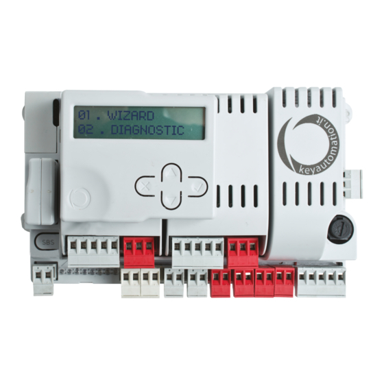
    2.1 - Beschreibung des Steuergerätes Das Steuergerät 14A ist ein modulares Steuersystem für Motoren kontinuierliche Überwachung des Steuergerätezustands erlaubt. von Key Automation zum elektrischen Öffnen und Schließen von Außerdem gewährleistet der Menüaufbau eine einfache Einstellung Flügel-, Schiebe- und Garagentoren sowie Schranken.
  • Seite 70: Technische Eigenschaften

    TECHNISCHE EIGENSCHAFTEN 14AF 14AB 14AB2 * 14AB2F ** Spannungsversorgung (L-N) 24Vac (+10%-15%) 50/60 Hz 230Vac (+10%-15%) 50/60 Hz Nennleistung 210W maximal 300W maximal 300W maximal Ausgang Spannungsversorgung Fotozellen 24 VDC (ungeregelt), maximal 250 mA Ausgang Blinkleuchte 24 VDC (ungeregelt), 25 W Ausgang zusätzliche Beleuchtung 24 VDC (ungeregelt), 15 W Ausgang Elektroschloss...
  • Seite 71: Produktinstallation

    4 - PRODUKTINSTALLATION 4.1 - Stromanschlüsse ACHTUNG - Vor dem Anschluss sicherstellen, dass die Stromzufuhr des Steuergerätes abgeschaltet ist. VERSORGUNGSANSCHLÜSSE Phase Spannungsversorgung 230 VAC 50-60 Hz Erde Nullleiter Spannungsversorgung 230 VAC 50-60 Hz ECLIPSE NEG POS NEG POS NEG POS NEG POS COM OUT COM OUT...
  • Seite 72: Elektrische Anschlüsse

    STROMANSCHLÜSSE FÜR LEISTUNGSMODUL PO24 ENERGIEEINSPARUNG (M1 - M2) 12/24 12/24 COM OUT AC/DC AC/DC 12/24 COM OUT 12/24 AC/DC AC/DC N.B.: Nur für Schiebetore ANSCHLÜSSE PO24 Eingang Endschalter 1 (nur für SUN) Eingang Endschalter 2 (nur für SUN) Gemeinsamer Anschluss Endschalter / Encoderspeisung + (12 VDC 50 mA MAX.) Eingang Encodersignal S Encoderspeisung - Ausgang Motor...
  • Seite 73: Verwendung Des Display-Programmiergerätes

    SCROLLEN Im Normalmodus, d. h. bei normaler Stromspeisung des Systems und angeschlossenem Display-Programmiergerät, X drücken, bis der Schriftzug KEY AUTOMATION erscheint. Das vollständige Fließdiagramm des Display-Programmiergerätes In diesem Modus sind folgende Statusmeldungen zu sehen: ist unter Punkt 6.3 auf S. 79 zu finden.
  • Seite 74: Bewegung Der Automatisierung Vom Display-Programmiergerät

    1. Die Installationsart und den entsprechenden Motortyp für die Installation auswählen: SCHNELLE MOTORTYP INSTALLATION PROGRAMMIERUNGSVERFAHREN AUSWÄHLEN ACHTUNG! Wird ein anderer Motor als der angeschlossene ausgewählt, kann dies Schäden an der Anlage zur Folge haben. 2. ÜBERPRÜFUNG DES ANSCHLUSSES DER SICHERHEITSVORRICHTUNGEN (LICHTSCHRANKE 1 – LICHTSCHRANKE 2 – SCHALTLEISTENTYP –...
  • Seite 75: Diagnose

    4.6 - Diagnose Mittels dieser Funktion können jederzeit verschiedene Parameter wie die Stromaufnahme oder die Geschwindigkeit der Motoren angezeigt werden.Wie folgt vorgehen: STROM MOTOR 1 (mA) STROM MOTOR 2 (mA) POSITION MOTOR 1 (%) POSITION MOTOR 2 (%) DIAGNOSE GESCHWINDIGKEIT MOTOR 1 (%) GESCHWINDIGKEIT MOTOR 2 (%) GESAMTZYKLEN (ZYKLEN) BIS ZUR WARTUNG AUSSTEHENDE ZYKLEN...
  • Seite 76 PARAMETER BESCHREIBUNG STANDARD MIN. MAX. EINHEIT Geschwindigkeit des Motors beim Schließen während der Verlangsamungsphase. GESCHWIN- 1 = minimal DIGKEIT BEI SOFT 2 = niedrig STOPP BEIM 3 = mittel SCHLIESSEN 4 = hoch 5 = maximal GESCHWIN- Geschwindigkeit des Motors beim Schließen DIGKEIT BEI SOFT während der Verlangsamungsphase.
  • Seite 77: Nachtbeleuchtung

    4.8 - Nachtbeleuchtung Funktion Nachtlichter läuft ordnungsgemäß NACHTBELEUCHTUNG angeschlossener Blinkleuchte Eclipse automatisch ab. Zur Anpassung an den eigenen Bedarf wie folgt vorgehen: PARAMETER BESCHREIBUNG STANDARD MIN. MAX. EINHEIT 0 = Night Light System deaktiviert AUTOMATISCHES 1 = Night Light System aktiv (automatisch BELEUCHTUNG beim Einlernen des Laufs aktiviert, wenn die Blinkleuchte ECLIPSE angeschlossen ist)
  • Seite 78: Vertiefung

    6 - VERTIEFUNG 6.1 - Benutzerdefinierte Einrichtung der Anlage - Fortgeschrittene Programmierung Bei Bedarf können über FORTGESCHRITTENE ACHTUNG: Die Parameter könnten je nach dem für die Installation PROGRAMMIERUNG zusätzliche Parameter der Steuereinheit gewählten Motor anders sein als in der Tabelle hier unten. angepasst werden.
  • Seite 79 PARAMETER BESCHREIBUNG STANDARD MIN. MAX. EINHEIT 0 = deaktiviert TOTMANN 1 = aktiviert (die Sicherheitsvorrichtungen werden deaktiviert) 0 = deaktiviert 1 = Kontrollleuchte Tor geöffnet ON/OFF 2 = Kontrollleuchte Tor geöffnet proportional 3 = Elektroschloss für Teilöffnung * ANZEIGELICHT 4 = Elektroschloss für Teilöffnung mit OFFENES TOR Relaisschnittstelle ** 5 = Ampel Von geöffnet Ausgang COM/IND...
  • Seite 80: Empfänger Rx4Y

    6.2 - Empfänger RX4Y Bei Bedarf kann das MENÜ EMPFÄNGER RX4X ausgewählt RX4Y werden, in dem die Funkparameter eingestellt werden können. Wie folgt vorgehen: SENDER HINZUFÜGEN Erlaubt das Speichern eines neuen Codes im Empfänger SENDER LÖSCHEN Erlaubt das Löschen eines vorhandenen Codes im Empfänger ALLES LÖSCHEN Löscht den gesamten Speicher des Empfängers SPEICHER LESEN...
  • Seite 81: Fließdiagramm Des Programmiergerätes

    6.3 - Fließdiagramm des Programmiergerätes SCHNELLE PROGRAMMIE- RUNGSVERFAHREN ▲ ▼ STROM MOTOR 1 (mA) VOLLES PROGRAMMIE- RUNGSVERFAHREN STROM MOTOR 2 (mA) POSITION MOTOR 1 (%) ▲ ▼ POSITION MOTOR 2 (%) DIAGNOSE GESCHWINDIGKEIT MOTOR 1 (%) GESCHWINDIGKEIT MOTOR 2 (%) ▲...
  • Seite 82 ÍNDICE Avisos sobre a segurança pag. 83 Introdução ao produto pág. 85 Descrição da unidade pág. 85 Descrição das ligações pág. 85 Modelos e características técnicas pág. 85 Lista de cabos necessários pág. 86 Controlos preliminares pág. 86 Instalação do produto pág.
  • Seite 83: Avvertenze Per La Sicurezza

    Assistên- devem ser feitas por pessoal qualificado e experiente, cia Key Automation. A utilização da automação nestas respeitando as instruções indicadas na caixa “Ensaio condições pode causar situações de perigo;...
  • Seite 84 A KEY AUTOMATION reserva-se o direito de mo- dificar estas instruções se necessário. Esta instalar qualquer controlo fixo a uma altura de, pelo versão ou versão superior encontra-se no sítio...
  • Seite 85: Introdução Ao Produto

    A unidade 14A é um sistema de controlo modular para os motores constantemente o estado da unidade; além disso, a estrutura em Key Automation para a abertura e o fecho elétrico de portões de menu permite configurar de forma simples os tempos de trabalho e batente, de correr, barreiras de controlo de acessos e portões de...
  • Seite 86: Verificações Preliminares

    CARACTERÍSTICAS TÉCNICAS 14AF 14AB 14AB2 * 14AB2F ** Alimentação (L-N) 24Vac (+10%-15%) 50/60 Hz 230Vac (+10%-15%) 50/60 Hz Potência nominal 210W máximo 300W máximo 300W máximo Saída de alimentação das fotocélulas 24Vdc (não regulado) máximo 250mA Saída da luz de sinalização intermitente 24Vdc (não regulado) 25W Saída da luz de cortesia 24Vdc (não regulado) 15W...
  • Seite 87: Instalação Do Produto

    4 - INSTALAÇÃO DO PRODUTO 4.1 - Ligações elétricas ATENÇÃO - Antes de fazer as ligações, verificar se a unidade não está ligada à alimentação elétrica. LIGAÇÕES DE ALIMENTAÇÃO Fase da alimentação 230 Vac 50-60 Hz Terra Neutro da alimentação 230 Vac 50-60 Hz ECLIPSE NEG POS NEG POS...
  • Seite 88: Ligações Elétricas

    LIGAÇÕES ELÉTRICAS MÓDULO DE POTÊNCIA PO24 PARA POUPANÇA DE ENERGIA (M1 - M2) 12/24 12/24 COM OUT AC/DC AC/DC 12/24 COM OUT 12/24 AC/DC AC/DC N.B.: Apenas para portões de correr LIGAÇÕES PO24 Entrada do fim de curso 1 (apenas para SUN) Entrada do fim de curso 2 (apenas para SUN) Comum do fim de curso / positivo de alimentação do encoder (12 Vdc 50 mA MAX) Entrada do sinal do encoder S...
  • Seite 89 No modo normal, ou seja, com o sistema alimentado normalmente e com o programador com ecrã ligado, premer X até aparecer a escrita KEY AUTOMATION. Deste modo, O diagrama de fluxo completo do programador com ecrã encontra- serão apresentadas as seguintes mensagens de estado: se no ponto 6.3, pág.
  • Seite 90 1. Selecionar o tipo de instalação e o respetivo tipo de motor a instalar: PROGRAMAÇÃO SELECIONAR UM INSTALAÇÃO RÁPIDA TIPO DE MOTOR ATENÇÃO: Selecionar um motor diferente do ligado pode causar danos ao sistema. 2. CONTROLO DA LIGAÇÃO DOS DISPOSITIVOS DE PROTEÇÃO (FOTO 1 – FOTO 2 – FUNCIONAMENTO BORDA SENSIVEL – PULSADOR DE STOP) Durante a programação pergunta-se se há...
  • Seite 91 4.6 - Diagnóstico Em qualquer momento é possível visualizar alguns parâmetros tais como a absorção de corrente ou a velocidade dos motores através desta função. Seguir as instruções abaixo: CORRENTE MOTOR 1 (mA) CORRENTE MOTOR 2 (mA) POSIÇÃO MOTOR 1 (%) POSIÇÃO MOTOR 2 (%) DIAGNÓSTICO VELOCIDADE MOTOR 1 (%)
  • Seite 92 PARÂMETROS DESCRIÇÃO DEFAULT MIN. MAX. UNIDADE Velocidade do motor na fase de abrandamento durante o fecho. REDUCAO 1 = mínima VELOCIDADE NA 2 = baixa ENCERRAMENTO 3 = média 4 = alta 5 = máxima Velocidade do motor na fase de abrandamento REDUCAO durante o fecho.
  • Seite 93: Luz Nocturna

    4.8 - Luz nocturna O funcionamento das luzes noturnas é automático com a luz de LUZ NOCTURNA sinalização Eclipse adequadamente ligada. Para personalizar, seguir as instruções. PARÂMETROS DESCRIÇÃO DEFAULT MIN. MAX. UNIDADE 0 = Night Light System desativado 1 = Night Light System ativado LUZ AUTOMÁTICO (automaticamente ativado durante a memorização do curso com luz intermitente...
  • Seite 94 6 - INFORMAÇÕES PORMENORIZADAS 6.1 - Personalização do sistema - Configurações avançados 14A Se necessário, é possível selecionar as CONFIGURAÇÕES ATENÇÃO: os parâmetros podem variar relativamente à tabela AVANÇADOS que permitem modificar os parâmetros avançados abaixo indicada com base na escolha do motor a instalar. da unidade de comando.
  • Seite 95 PARÂMETROS DESCRIÇÃO DEFAULT MIN. MAX. UNIDADE 0 = desabilitado HOMEM 1 = habilitado (os dispositivos de proteção são PRESENTE desabilitados) 0 = desativado 1 = led de portão aberto ON/OFF 2 = led de portão aberto proporcional 3 = fechadura elétrica para abertura para parcial* INDICADOR 4 = fechadura elétrica para abertura para parcial com...
  • Seite 96 6.2 - Recetor RX4Y Em caso de necessidade, é possível selecionar o MENU RECETOR RX4Y RX4X que permite controlar os parâmetros relativos ao recetor rádio. Seguir as instruções abaixo: ADICIONAR TX Permite memorizar um novo código no recetor ELIMINAR TX Permite eliminar um código presente no recetor ELIMINAR TUDO Elimina toda a memória do recetor...
  • Seite 97 6.3 - Diagrama de fluxo do programador PROGRAMAÇÃO RÁPIDA ▲ ▼ PROGRAMAÇÃO CORRENTE MOTOR 1 (mA) COMPLETA CORRENTE MOTOR 2 (mA) POSIÇÃO MOTOR 1 (%) ▲ ▼ POSIÇÃO MOTOR 2 (%) DIAGNÓSTICO VELOCIDADE MOTOR 1 (%) VELOCIDADE MOTOR 2 (%) ▲...
  • Seite 98 SPIS TREŚCI Uwagi dotyczące bezpieczeństwa pag. 99 Informacje wstępne o produkcie str. 101 Opis centrali str. 101 Opis podłączeń str. 101 Modele i parametry techniczne str. 101 Wykaz niezbędnych przewodów elektrycznych str. 102 Kontrole wstępne str. 102 Montaż produktu str. 103 Podłączenia elektryczne str.
  • Seite 99: Uwagi Dotyczące Bezpieczeństwa

    Ponadto wspomniany personel zobowiązany jest do z serwisem technicznym Key Automation. Użytkowanie przeprowadzenia odpowiednich testów, w zależności automatyki w powyższej sytuacji stanowi źródło od występujących zagrożeń, oraz do sprawdzenia, zagrożenia.
  • Seite 100 KEY AUTOMATION zastrzega sobie prawo do otwierając się całkowicie; modyfikowania niniejszej instrukcji w razie takiej potrzeby. Wersja aktualna, i/lub nowsze wersje stały element sterujący zamontować...
  • Seite 101: Opis Centrali

    2 - INFORMACJE OGÓLNE DOTYCZĄCE PRODUKTU 2.1 – Opis centrali Centrala 14A jest modułowym układem kontroli do silników Key (w opcji), ułatwiający czynności programowania oraz umożliwiający Automation, służącym do elektrycznego otwierania i zamykania nieustanne monitorowanie stanu centrali. Ponadto struktura menu ogrodzeniowych bram skrzydłowych, przesuwnych, szlabanów pozwala na łatwe ustawianie czasów pracy oraz logik działania.Menu i bram garażowych.
  • Seite 102: Wykaz Niezbędnych Przewodów Elektrycznych

    CARATTERISTICHE TECNICHE 14AF 14AB 14AB2 * 14AB2F ** Zasilanie (L-N) 24Vac (+10%-15%) 50/60 Hz 230Vac (+10%-15%) 50/60 Hz Moc nominalna 210 W maks 300 W maks 300 W maks Wyjście zasilania fotokomórek 24 VDC (nieregulowana) maks. 250 mA Wyjście lampy ostrzegawczej 24 VDC (nieregulowana) 25 W Wyjście świateł...
  • Seite 103: Montaż Produktu

    4 - MONTAŻ PRODUKTU 4.1 - Podłączenia elektryczne UWAGA – przed przystąpieniem do wykonywania podłączeń sprawdzić, czy do centrali nie jest doprowadzone zasilanie. PODŁĄCZENIA ZASILANIA Faza zasilania, 230 VAC 50-60 Hz Uziemienie Zero zasilania, 230 VAC 50-60 Hz ECLIPSE NEG POS NEG POS NEG POS NEG POS...
  • Seite 104 PODŁĄCZENIA ELEKTRYCZNE MODUŁ MOCY PO24 NA OSZCZĘDNOŚĆ ENERGII (M1 - M2) 12/24 12/24 COM OUT AC/DC AC/DC 12/24 COM OUT 12/24 AC/DC AC/DC Uwaga: wyłącznie do bram przesuwnych PODŁĄCZENIA PO24 Wejście wyłącznika krańcowego 1 (tylko do SUN) Wejście wyłącznika krańcowego 2 (tylko do SUN) Wyłącznik krańcowy wspólny / plus zasilania enkodera (12 VDC 50 mA MAKS) Wejście sygnału enkodera S Minus zasilania enkodera...
  • Seite 105: Obsługa Programatora Z Wyświetlaczem

    W DÓŁ z wyświetlaczem, wciskać X do momentu, aż pojawi się napis KEY AUTOMATION.W ten sposób można będzie zobaczyć Kompletny wykres funkcji programatora z wyświetlaczem znajduje następujące komunikaty stanu: się w punkcie 6.3 na str. 111.
  • Seite 106: Sterowanie Automatyką Poprzez Programator Z Wyświetlaczem

    1. Wybrać rodzaj montażu oraz odpowiedni rodzaj silnika do zamontowania: SZYBKIE WYBRAĆ MONTAŻ PROGRAMOWANIE RODZAJ SILNIKA UWAGA! Wybór silnika innego od podłączonego, może spowodować uszkodzenie instalacji. 2. SPRAWDZENIE PODŁĄCZEŃ URZĄDZEŃ ZABEZPIECZAJĄCYCH (FOTO 1 – FOTO 2 - LISTWA KRAWĘDZIOWA FUNKCJONOWANIE – PRZYCISK STOP). Podczas programowania zostanie wyświetlone pytanie, które z zabezpieczeń...
  • Seite 107: Diagnostyka

    4.6 – Diagnostyka W dowolnym momencie możliwe jest wyświetlenie przy pomocy tej funkcji niektórych parametrów, takich jak pobór prądu oraz prędkość silników.Postępować wg poniższej procedury: PRĄD SILNIKA 1 (mA) PRĄD SILNIKA 2 (mA) POŁOŻENIE SILNIKA 1 (%) POŁOŻENIE SILNIKA 2 (%) DIAGNOSTYKA PRĘDKOŚĆ...
  • Seite 108 PARAMETRY OPIS DOMYŚLNA MIN. MAKS. JEDNOSTKA Prędkość silnika w fazie zwalniania podczas zamykania. PRĘDKOŚĆ 1 = minimalna SPOWOLNIENIA 2 = mała PRZY ZAMYKANIU 3 = średnia 4 = duża 5 = maksymalna Prędkość silnika w fazie zwalniania podczas PRĘDKOŚĆ zamykania. SPOWOLNIENIA 1 = minimalna PRZY ZAMYKANIU...
  • Seite 109: Nocna Lampa

    4.8 - Nocna lampa Działanie oświetlenia nocnego odbywa się w trybie automatycznym, NOCNA LAMPA po odpowiednim podłączeniu lampy ostrzegawczej Eclipse. Aby dokonać indywidualnego dostosowania: PARAMETRY OPIS DOMYŚLNA MIN. MAKS. JEDNOSTKA 0 = Night Light System nieaktywny 1 = Night Light System aktywny (aktywowany AUTOMATYCZNE automatycznie podczas programowania SWIATLA NOCNE...
  • Seite 110: Instrukcje Szczegółowe

    6 – INSTRUKCJE SZCZEGÓŁOWE 6.1 – Indywidualne dostosowanie urządzenia – Ustawienia Zaawansowane W przypadku takiej konieczności można wybrać USTAWIENIA UWAGA: parametry mogą różnić się od wartości podanych w ZAAWANSOWANE, które umożliwiają zmianę zaawansowanych poniższej tabeli, w zależności od wybranego rodzaju silnika do parametrów centrali.
  • Seite 111 PARAMETRY OPIS DOMYŚLNA MIN. MAKS. JEDNOSTKA 0 = nieaktywne OBECNOŚĆ 1 = aktywne (zostają wyłączone urządzenia UZYTKOWNIKA zabezpieczające) 0 = nieaktywna 1 = kontrolka brama otwarta ON/OFF 2 = kontrolka brama otwarta proporcjonalnie 3 = elektrozamek do częściowe pieszego * LAMPKA STANU 4 = elektrozamek do częściowe pieszego z BRAMY...
  • Seite 112 6.2 - Odbiornik RX4Y W przypadku takiej konieczności, można wybrać MENU ODBIORNIKA RX4Y RX4X, które umożliwia zarządzanie parametrami radia. Postępować wg poniższej procedury: DODAJ TX Umożliwia zapisywanie nowego kodu w odbiorniku. SKASUJ TX Umożliwia kasowanie kodu zapisanego w odbiorniku. SKASUJ WSZYSTKO Kasuje całą...
  • Seite 113: Wykres Funkcji Programatora

    6.3 – Wykres funkcji programatora SZYBKIE PROGRA- MOWANIE ▲ ▼ PRĄD SILNIKA 1 (mA) PEŁNE PROGRAMO- WANIE PRĄD SILNIKA 2 (mA) POŁOŻENIE SILNIKA 1 (%) ▲ ▼ POŁOŻENIE SILNIKA 2 (%) DIAGNOSTYKA PRĘDKOŚĆ SILNIKA 1 (%) PRĘDKOŚĆ SILNIKA 2 (%) ▲...
  • Seite 114: Declaration Of Conformity

    7 - DECLARATION OF CONFORMITY DICHIARAZIONE DI INCORPORAZIONE DI QUASI-MACCHINA DECLARATION OF INCORPORATION OF PARTLY COMPLETED MACHINERY Il so�oscri�o Nicola Michelin, Amministratore Delegato dell’azienda The undersigned Nicola Michelin, General Manager of the company Key Automa�on srl, Via Meucci, 23 - 30027 San Donà di Piave (VE) – ITALIA dichiara che il prodo�o �po: declares that the product type: Centrale di comando modulare a 24 Vdc...
  • Seite 116 Key Automation S.r.l. Via Meucci 23 - 30027 San Donà di Piave (VE) T. +39 0421 307456 - F. +39 0421 65698 Instruction version info@keyautomation.it - www.keyautomation.it 580IS14A REV.13...

Diese Anleitung auch für:

14a14af14ab14ab214ab2f

Inhaltsverzeichnis