Herunterladen Inhalt Inhalt Diese Seite drucken
Inhaltsverzeichnis

Werbung

Verfügbare Sprachen
  • DE

Verfügbare Sprachen

  • DEUTSCH, seite 37
Copyright © 2014 EATON
All rights reserved.
Service and support:
Call your local service representative
ATS-01_EN
Downloaded from
www.Manualslib.com
manuals search engine
EATON ATS 30
EATS30N
EATS30H
EATS30P
Installation
and user manual

Werbung

Inhaltsverzeichnis
loading

Inhaltszusammenfassung für Eaton ATS 30

  • Seite 1 EATON ATS 30 EATS30N EATS30H EATS30P Installation and user manual Copyright © 2014 EATON All rights reserved. Service and support: Call your local service representative ATS-01_EN Downloaded from www.Manualslib.com manuals search engine...
  • Seite 2: Safety Instructions

    SAVE THESE INSTRUCTIONS. This manual contains important instructions that should be followed during installation and maintenance of the ATS. The EATON ATS models that are covered in this manual are intended for installation in an environment within 40°C/104°F (EATS30H, EATS30P) and 35°C/95°F (EATS30N), free of conductive contaminant.
  • Seite 3: Inhaltsverzeichnis

    Contents 1. Introduction ..................4 2. Presentation ..................4 Weights and dimensions ....................4 Front panel layout ......................4 3. Installation for ATS ................5 Checking the accessory kit ....................5 Storage ..........................5 Front installation for rack mounting ................6 Rear installation for rack mounting ................6 Instructions ........................6 4.
  • Seite 4: Introduction

    1. Introduction The EATON ATS 30 is designed to guarantee the uninterrupted operation of sensitive equipment. It is powered by two independent power sources and automatically makes a rapid switch form one source to the other when the power supply used to power its connected load fails. T his ATS is designed to be efficient and reliable. Users can know power flow and the EATON ATS 30's status from the user-friendly front panel. Besides, the unit has a network interface for users to read and write parameters.
  • Seite 5: Installation For Ats

    3. Installation for ATS Checking the accessory kit • Verify that the following additional items are included with the ATS: EATS30N - EATS30H User manual Safety instructions Warranty sheet (EATS30H) ATS module Rack mounting bracket EATS30P User manual Safety instructions Warranty sheet (EATS30H) ATS module Rack mounting bracket...
  • Seite 6: Front Installation For Rack Mounting

    3. Installation for ATS Front installation for rack mounting Follow steps 1 to 3 for module mounting on the rails. Rear installation for rack mounting Follow steps 1 to 3 for module mounting on the rails. Instructions 1. Elevated Operating Ambient - If installed in a closed or multi-unit rack assembly, the operating ambient temperature of the rack environment may be greater than room ambient.
  • Seite 7: Power Cables Connection

    After power connection, the Eaton ATS will automatically perform power-on self-test. After the test, the Eaton ATS will start supplying power to its connected equipment. You can also press the ‘Test Button’ to force the Eaton ATS to execute self-test.
  • Seite 8: Access To Terminal Blocks Eats30N - Eats30H

    4. Power cables connection Access to terminal blocks EATS30N - EATS30H Hardwired Input/Output connection (EU) EATS30N - EATS30H 1. Connect input power cables to two UPSs (UPS1 (S1) is the preferred source). 2. Connect output power cable to load. To UPS 1 To UPS 2 To load Cable cross sections...
  • Seite 9: Operation

    LED will light up as green. If not, this LED will be off. Fault LED If the Eaton ATS has any internal fault, this LED will light up as red. If the Eaton ATS has any environmental fault, this LED will flash (ON: 0.5s;...
  • Seite 10: Communication Card

    5. Operation Communication card N° Indicator Description NETWORK port Connects to the Ethernet Network LOCAL port Connects to a workstation with an RJ45 to DB9 cable to configure the system. RESET button Resets InsightPower SNMP IPv6 for ATS (hereafter referred to as SNMP IPv6).
  • Seite 11: Troubleshooting

    6. Troubleshooting Problem Possible cause Action All LEDs on the front The power sources, S1 and S2, are 1. Check the output panel are off both absent (overload/short-circuit) 2. Check both power sources, S1 and S2 3. Reset the upstream circuit breakers S1 or S2 LED is off The corresponding power source 1.
  • Seite 12: Specifications

    7. Specifications Table 1. Model list Model Operating voltage Current rating Operating frequency EATS30N 180V to 264V 30A for CE 45Hz to 65Hz EATS30H 24A for UL EATS30P 24A for UL Table 2. Weights and dimensions Model Dimensions H x W x D (inch/mm) Weight (lb/kg) 1.7 x 17.4 x 15.4 / 43 x 440 x 390 10.6 / 4.8...
  • Seite 13 EATON ATS 30 EATS30N EATS30H EATS30P Manuel d'installation et d'utilisation Copyright © 2014 EATON Tous droits réservés. SAV et assistance : Contacter votre représentant SAV local ATS-01_FR Downloaded from www.Manualslib.com manuals search engine...
  • Seite 14: Instructions De Sécurité

    INSTRUCTIONS DE SÉCURITÉ ENREGISTREZ CES INSTRUCTIONS. Ce manuel contient des instructions importantes qui doivent être suivies lors de l'installation et la maintenance de l'ATS. Les modèles EATON ATS faisant l'objet de ce manuel sont conçus pour être installés dans un environnement compris entre 40°C/104°F (EATS30H, EATS30P) et 35°C/95°F (EATS30N) exempt de contaminants conducteurs. Normes de certification • Sécurité : UL (US) (UL 60950) CE (EU) (IEC 60950) PSE (JP)
  • Seite 15 Table des matières 1. Introduction ..................4 2. Présentation ..................4 Poids et dimensions .......................4 2.2 Configuration du panneau avant ..................4 3. Installation pour l'ATS ..............5 3.1 Vérification du kit d'accessoires ..................5 Stockage ........................5 3.3 Installation à l'avant pour le montage en rack ...............6 3.4 Installation à l'arrière pour le montage en rack .............6 Instructions ........................6 4. Branchement des câbles d'alimentation ........7 4.1 Conditions requises pour l'installation ................7 4.2 Accès aux borniers EATS30N - EATS30H ..............8 4.3 Connexion d'entrée/de sortie câblée (UE) EATS30N - EATS30H ........8...
  • Seite 16: Introduction

    1. Introduction L'EATON ATS 30 est conçu pour garantir le fonctionnement ininterrompu d'un équipement sensible. Il est alimenté par deux sources d'alimentation indépendantes et permet de basculer rapidement et automatiquement d'une source à une autre en cas de défaillance de l'alimentation électrique utilisée pour alimenter sa charge connectée. L'ATS est conçu pour être efficace et fiable. Les utilisateurs peuvent connaître la circulation d'énergie et l'état de l'EATON ATS 30 à l'aide du panneau avant convivial. Par ailleurs, l'unité dispose d'une interface réseau permettant aux utilisateurs de lire et d'écrire des paramètres. L'interface réseau peut être mise en œuvre via le protocole Ethernet par le biais d'un connecteur RJ45. T outes les informations sont disponibles sur le panneau avant et le port LOCAL sur le panneau avant est disponible via le réseau par le biais du connecteur RJ45. 2. Présentation Poids et dimensions Position rack Description Poids Dimensions H x L x P...
  • Seite 17: Installation Pour L'ats

    3. Installation pour l'ATS Vérification du kit d'accessoires • Vérifiez que les éléments complémentaires suivants sont inclus avec l'ATS : EATS30N - EATS30H Manuel d'utilisation Instructions de sécurité Fiche de garantie (EATS30H) Module ATS Supports de montage en rack EATS30P Manuel d'utilisation INSTRUCTIONS DE SÉCURITÉ Fiche de garantie (EATS30P) Module ATS Supports de montage en rack Stockage • Veuillez stocker l'ATS dans son emballage d'origine et dans un endroit sec.
  • Seite 18: Installation À L'avant Pour Le Montage En Rack

    3. Installation pour l'ATS Installation à l'avant pour le montage en rack Suivez les étapes 1 à 3 pour le montage du module sur rails. Installation à l'arrière pour le montage en rack Suivez les étapes 1 à 3 pour le montage du module sur rails. Instructions 1. T empérature ambiante de fonctionnement - S'il est installé dans un rack fermé ou un rack avec plusieurs produits, la température ambiante de fonctionnement peut être supérieure à la température ambiante de la pièce. Par conséquent, il faudrait envisager d'installer l'équipement dans un environnement compatible avec la température ambiante maximale (Tma) spécifiée par le fabricant. 2. Débit d'air réduit - Installation de l'équipement dans un rack doit être telle que la quantité de flux d'air nécessaire au bon fonctionnement de l'équipement ne soit pas compromise. 3. Charge mécanique – L’installation de l'équipement dans le rack ne doit pas induire de situations de danger liée à une mauvaise charge mécanique. 4. S urcharge des circuits - L'effet d’une surcharge électrique sur les protection et sur les câbles d'alimentation doit être pris en compte. L’évaluation de l’équipement et de sa plaque signalétique doit être menée à cet effet.
  • Seite 19: Branchement Des Câbles D'alimentation

    Dispositifs de protection recommandés Protection recommandée Disjoncteur bipolaire UPS S1 pour l'équipement sensible Disjoncteur bipolaire UPS S2 Après le raccordement électrique, l'Eaton ATS effectue automatiquement un autotest de mise sous tension. Une fois le test terminé, l'Eaton ATS commence à alimenter son équipement connecté. Vous pouvez également appuyer sur le bouton de test pour forcer l'Eaton ATS à exécuter un autotest. Entrée recommandée et le cordon de sortie pour EATS30H Cordon d'entrée: • UL • de type non-amovible • Max. 4,5 m (14,76 pi.) • Min.
  • Seite 20: Accès Aux Borniers Eats30N - Eats30H

    4. Branchement des câbles d'alimentation Accès aux borniers EATS30N - EATS30H Connexion d'entrée/de sortie câblée (UE) EATS30N - EATS30H 1. C onnectez les câbles d'alimentation d'entrée à deux onduleurs (UPS1 (S1) est la source privilégiée). 2. C onnectez le câble d'alimentation de sortie à la charge. Vers onduleur 1 Vers onduleur 2 Vers la charge Sections de câbles Position Fonction...
  • Seite 21: Interface Utilisateur

    5. Fonctionnement Interface utilisateur Le tableau suivant indique l'état du voyant et fournit une description : N° Voyant État Description Bouton Test Utilisez ce bouton pour tester l'Eaton ATS. Si vous appuyez sur ce bouton, l'Eaton ATS passe sur la 2e source pendant 1 minute, puis revient sur sa source d'origine privilégiée. LED de test Vert Si vous appuyez sur le bouton de test, l'Eaton ATS se met en condition de test et la LED de test clignote (allumée : 0,5 s ;éteinte : 0,5 s). En fonctionnement normal, cette LED est éteinte. LED S1 Vert Cette LED indique l'état de la source d'entrée 1. Si la source d'entrée 1 se situe dans une plage acceptable, cette LED s'allume en vert. Si la source d'entrée 1 se situe hors de la plage acceptable, cette LED est éteinte. LED S2 Vert Cette LED indique l'état de la source d'entrée 2. Si la source d'entrée 2 se situe dans une plage acceptable, cette LED s'allume en vert.
  • Seite 22: Fonctionnement

    5. Fonctionnement Carte de communication N° Voyant Description Port « NETWORK » Établit la connexion au réseau Ethernet (RÉSEAU) Port LOCAL Établit la connexion à une station de travail avec un câble RJ45 vers DB9 pour configurer le système. Bouton RESET Réinitialise la carte SNMP IPv6 de l’ATS (ci-après dénommé SNMP IPv6). (RÉINITIALISER) Cela n'altère pas le fonctionnement de l'ATS Voyants LED LED réseau (vert) indique l'état de communication du réseau LED ATS (jaune) indique l'état de communication de l'ATS.
  • Seite 23: Dépannage

    6. Dépannage Symptôme Cause Action Toutes les LED du Les sources d'alimentation, S1 et 1. Vérifiez la sortie panneau avant sont S2, sont toutes deux absentes (surcharge/court-circuit) éteintes 2. V érifiez les deux sources d'alimentation, S1 et S2 3. Réinitialisez les disjoncteurs en amont La LED S1 ou S2 est La source d'alimentation 1. V érifiez la source d'alimentation éteinte...
  • Seite 24: Spécifications

    7. Spécifications Tableau 1. Liste de modèles Modèle Tension de Courant nominal Fréquence de fonctionnement fonctionnement EATS30N 180 V à 264 V 30 A pour CE 45 Hz à 65 Hz EATS30H 24 A pour UL EATS30P 24 A pour UL Tableau 2.Poids et dimensions Modèle Dimensions H x L x P (mm/inch) Poids (kg / lb) 43 x 440 x 390/1,7 x 17,4 x 15,4 4,8/10,6 EATS30N...
  • Seite 25 EATON ATS 30 EATS30N EATS30H EATS30P Инструкции по установке и руководство пользователя Copyright © 2014 EATON Все права защищены. Обслуживание и поддержка: Обращайтесь к своему местному представителю по обслуживанию ATS-00_RU Downloaded from www.Manualslib.com manuals search engine...
  • Seite 26: Правила Техники Безопасности

    СОХРАНИТЕ ЭТИ ИНСТРУКЦИИ. В этом руководстве содержатся важные инструкции, которым необходимо следовать при установке и техобслуживании ATS. Модели устройства EATON ATS, для которых составлено это руководство, предназначены для установки и работы в среде, не содержащей электропроводящих загрязняющих веществ, при температуре...
  • Seite 27 Содержание 1. Введение ..................4 2. Общая информация ............... 4 Вес и размеры ............................4 Компоновка передней панели ........................4 3. Установка ATS .................. 5 Проверка комплектности вспомогательных принадлежностей ............. 5 Хранение ..............................5 Установка в стойку с креплением спереди ..................... 6 Установка...
  • Seite 28: Введение

    источниками происходит автоматически в случае сбоя подачи питания на подключенные нагрузки с одного из источников. Конструкция устройства ATS отличается эффективностью и надежностью. Потокораспределение и состояние оборудования EATON ATS 30 пользователи отслеживают по показаниям индикаторов на удобной в использовании передней панели. Кроме того, для считывания и записи...
  • Seite 29: Установка Ats

    3. Установка ATS Проверка комплектности вспомогательных принадлежностей • Следует убедиться, что в комплект ATS включены следующие дополнительные компоненты: EATS30N - EATS30H Руководство пользователя Правила техники безопасности Гарантийный листок (EATS30H) Модуль ATS Кронштейны для монтирования в стойку EATS30P Руководство пользователя Правила техники безопасности Гарантийный...
  • Seite 30: Установка В Стойку С Креплением Спереди

    3. Установка ATS Установка в стойку с креплением спереди Выполните шаги 1–3 процедуры установки модуля на рельсы. Установка в стойку с креплением сзади Выполните шаги 1–3 процедуры установки модуля на рельсы. Страница 6 ATS-00_RU Downloaded from www.Manualslib.com manuals search engine...
  • Seite 31: Подсоединение Кабелей Питания

    к чувствительному оборудованию 2-полюсный выключатель UPS S2 После подключения к сети энергоснабжения устройство Eaton ATS автоматически запускает процедуру самопроверки при включении питания. После завершения проверки устройство Eaton ATS начинает подавать питание на подключенное оборудование. Для принудительного запуска самопроверки Eaton ATS можно...
  • Seite 32: Доступ К Клеммным Колодкам

    4. Подсоединение кабелей питания Доступ к клеммным колодкам EATS30N–EATS30H Фиксированное входное/выходное соединение (EU) EATS30N–EATS30H 1. Подсоединить входные силовые кабели к двум источникам бесперебойного питания (ИБП1 (S1) — предпочтительный источник). 2. Подсоединить выходной силовой кабель к нагрузке. К ИБП 1 К ИБП 2 к...
  • Seite 33: Эксплуатация

    В случае любой внутренней ошибки устройства Eaton ATS этот неисправности светодиод загорается красным. В случае любой внешней ошибки Eaton ATS этот светодиод мигает (горит: 0,5 с; не горит: 0,5 с). Сообщения об ошибках передаются на подключенный ПК через порт «NETWORK». С компьютера можно просматривать коды ошибок (см.
  • Seite 34: Сетевая Карта

    5. Эксплуатация Сетевая карта № Индикатор Описание Порт NETWORK Служит для подключения к сети Ethernet Порт LOCAL Служит для подключения к рабочей станции с помощью кабеля RJ45– DB9 с целью конфигурирования системы. Кнопка RESET Используется для перезагрузки ПО InsightPower SNMP IPv6 для устройства ATS (далее...
  • Seite 35: Устранение Неисправностей

    6. Устранение неисправностей Признак Возможная причина Действие Не горят все Отсутствуют оба источника 1. Проверить выход светодиодные питания — S1 и S2. (на наличие перегрузки или короткого индикаторы на передней замыкания). панели. 2. Проверить оба источника питания — S1 и S2. 3.
  • Seite 36: Технические Характеристики

    7. Технические характеристики Таблица 1. Список моделей Модель Рабочее напряжение Номинальный ток Рабочая частота EATS30N 180–264 В 30 A для CE 45–65 Гц EATS30H 24 A для UL EATS30P 24 A для UL Таблица 2. Вес и размеры Модель Размеры выс. H x шир. L x глуб. P Вес...
  • Seite 37 EATON ATS 30 EATS30N EATS30H EATS30P Installations- und Bedienungsanleitung Copyright © 2014 EATON Alle Rechte vorbehalten. Service und Support: Wenden Sie sich telefonisch an Ihren örtlichen Servicepartner. ATS-00_DE Downloaded from www.Manualslib.com manuals search engine...
  • Seite 38: Sicherheitsanweisungen

    BEWAHREN SIE DIESE ANLEITUNG AUF. Diese Anleitung enthält wichtige Anweisungen, die während der Installation und Wartung des ATS zu beachten sind. Die in dieser Anleitung beschriebenen Modelle des EATON ATS sind für eine Installation in Umgebungen mit Temperaturen von 40°C/104°F (EATS30H, EATS30P) und 35°C/95°F (EATS30N) und frei von leitenden Kontaminationen vorgesehen.
  • Seite 39 Inhalt 1. Einführung ..................4 2. Übersicht ................... 4 Gewicht und Maße ......................4 Bedienfeld ........................4 3. Installation des ATS ................5 Überprüfung des Zubehörs ....................5 Lagerung ........................5 3.3 Installation für die Montage im Rack nach vorn ............6 Installation für die Montage im Rack nach hinten ............6 4. Anschluss der Stromkabel ............... 7 Installationsanforderungen.....................7 Zugriff auf Klemmenblöcke ....................8 4.3 Fest verdrahteter Eingangs-/Ausgangsanschluss (EU)...........8...
  • Seite 40: Einführung

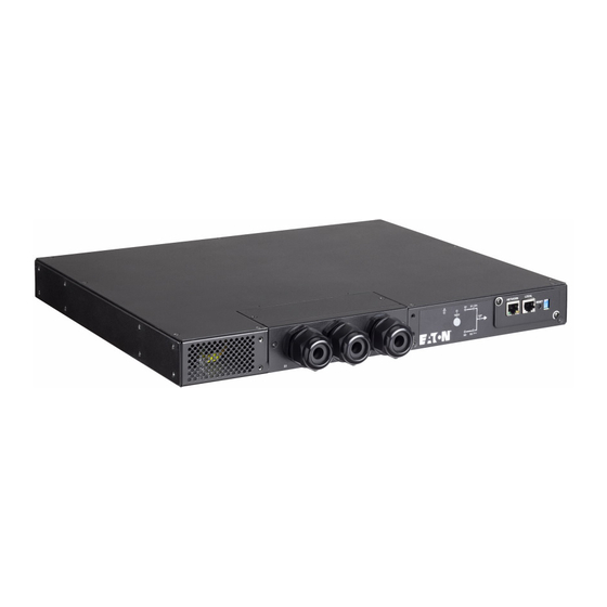
    Das benutzerfreundliche Bedienfeld informiert den Benutzer über die bestehende Stromversorgung und den Status des EATON ATS 30. Zudem verfügt die Einheit über eine Netzwerkschnittstelle, über die die Benutzer Parameter auslesen und eingeben können. Die Netzwerkschnittstelle lässt sich über einen RJ45-Stecker per Ethernet-Protokoll verwenden.
  • Seite 41: Installation Des Ats

    3. Installation des ATS Überprüfung des Zubehörs • Vergewissern Sie sich, dass folgende zusätzliche Teile mit dem ATS geliefert wurden: EATS30N - EATS30H Benutzerhandbuch Sicherheitsanweisungen Garantiekarte (EATS30H) ATS-Modul Halterung zur Montage im Rack EATS30P Benutzerhandbuch Sicherheitsanweisungen Garantiekarte (EATS30P) ATS-Modul Halterung zur Montage im Rack Lagerung • Bewahren Sie den ATS in seiner Originalverpackung an einem trockenen Ort auf.
  • Seite 42: Installation Für Die Montage Im Rack Nach Vorn

    3. Installation des ATS Installation für die Montage im Rack nach vorn Befolgen Sie zur Montage des Moduls auf den Schienen die Schritte 1 bis 3. Installation für die Montage im Rack nach hinten Befolgen Sie zur Montage des Moduls auf den Schienen die Schritte 1 bis 3. Seite 6 ATS-00_DE Downloaded from...
  • Seite 43: Anschluss Der Stromkabel

    Nach Anschluss der Stromversorgung führt der Eaton ATS beim Einschalten automatisch einen Selbsttest durch Nach dem Test beginnt der Eaton ATS die angeschlossenen Geräte mit Strom zu versorgen. Mit dem „ Test“-Knopf können Sie zudem unabhängig einen Selbsttest des Eaton ATS durchführen.
  • Seite 44: Zugriff Auf Klemmenblöcke

    4. Anschluss der Stromkabel Zugriff auf Klemmenblöcke EATS30N - EATS30H Fest verdrahteter Eingangs-/Ausgangsanschluss (EU) EATS30N - EATS30H 1. Schließen Sie die Netzkabel an zwei USV an (USV1 (S1) ist die bevorzugte Stromquelle). 2. Schließen Sie das Ausgangskabel an die zu versorgenden Geräte an. Zu USV 1 Zu USV 2 Zum versorgten Gerät...
  • Seite 45: Betrieb

    Störungs-LED Rot Wenn am Eaton ATS eine interne Störung anliegt, leuchtet dieser LED rot. Wenn in der Umgebung des Eaton ATS eine Störung anliegt, blinkt dieser LED (ein: 0,5 s; aus: 0,5 s). Über den „NETWORK“-Port werden Fehlermeldungen an einen angeschlossenen PC geschickt.
  • Seite 46: Kommunikationskarte

    5. Betrieb Kommunikationskarte Anzeige Beschreibung NETWORK-Port Anschluss zum Ethernet-Network. LOCAL-Port Anschluss an eine Workstation per RJ45 zu einem DB9-Kabel, um das System zu konfigurieren. RESET-Knopf Setzt InsightPower SNMP IPv6 für ATS zurück (im Folgenden als SNMP IPv6 bezeichnet). Dies hat keinen Einfluss auf den Betrieb des ATS. LED-Leuchten NETWORK-LED (grün) gibt den Kommunikationsstatus mit dem Netzwerk an.
  • Seite 47: Troubleshooting

    6. Troubleshooting Problem Mögliche Ursache Maßnahme Alle LEDs an der Beide Stromquellen (S1 und S2) 1. Überprüfen Sie die Ausgangsleistung Vorderseite des Geräts sind nicht verfügbar (Überladung/Kurzschluss) sind aus 2. Überprüfen Sie beide Stromquellen (S1 und S2) 3. Setzen Sie die vorgeschalteten Leistungsschalter zurück LED S1 oder S2 ist aus Die entsprechende Stromquelle...
  • Seite 48: Technische Daten

    7. Technische Daten Tabelle 1. Modellliste Modell Betriebsspannung Nennstrom Betriebsfrequenz EATS30N 180 V bis 264 V 30 A für CE 45 Hz bis 65 Hz EATS30H 24 A für UL EATS30P 24 A für UL Tabelle 2. Gewicht und Maße Modell Maße H x B x T (Zoll/mm) Gewicht (Pfund/kg)
  • Seite 49 EATON ATS 30 EATS30N EATS30H EATS30P Manual de instalación y del usuario Copyright © 2014 EATON Todos los derechos reservados. Servicio y soporte: Llame a su representante de servicio local. ATS-00_ES Downloaded from www.Manualslib.com manuals search engine...
  • Seite 50: Instrucciones De Seguridad

    GUARDE ESTAS INSTRUCCIONES. Este manual contiene instrucciones importantes que son necesarias para la instalación y el mantenimiento del ATS. Los modelos EATON ATS descritos en este manual deben instalarse en un entorno entre 40°C/104°F (EATS30H, EATS30P) y 35°C/95°F (EATS30N) sin contaminantes conductivos.
  • Seite 51 Contenido 1. Introducción ..................4 2. Presentación ..................4 Pesos y dimensiones .....................4 Disposición del panel frontal ..................4 3. Instalación del ATS ................5 Comprobación del kit de accesorios ................5 Almacenamiento ......................5 Instalación delantera para montaje en rack ..............6 Instalación trasera para montaje en rack ..............6 4.
  • Seite 52: Introducción

    1. Introducción El interruptor de transferencia automática EATON ATS 30 está diseñado para garantizar un funcionamiento ininterrumpido de los equipos sensibles. Recibe alimentación de dos fuentes independientes y conmuta rápidamente de una a otra si falla el suministro de corriente utilizado para la carga conectada. Este ATS está diseñado para actuar de forma eficiente y fiable. Los usuarios pueden consultar el flujo de corriente y el estado del EATON ATS 30 en el panel frontal de fácil manejo. Además, la unidad dispone de una interfaz de red para que los usuarios escriban y lean los parámetros.
  • Seite 53: Instalación Del Ats

    3. Instalación del ATS Comprobación del kit de accesorios • Compruebe que se hayan incluido los siguientes elementos adicionales en el ATS: EATS30N - EATS30H Manual del usuario Instrucciones de seguridad Hoja de garantía (EATS30H) Módulo ATS Soporte de montaje en rack EATS30P Manual del usuario Instrucciones de seguridad...
  • Seite 54: Instalación Delantera Para Montaje En Rack

    3. Instalación del ATS Instalación delantera para montaje en rack Siga los pasos 1 a 3 para montar el módulo en los raíles. Instalación trasera para montaje en rack Siga los pasos 1 a 3 para montar el módulo en los raíles. Página 6 ATS-00_ES Downloaded from www.Manualslib.com manuals search engine...
  • Seite 55: Conexión De Los Cables De Alimentación

    Disyuntor de dos polos UPS S2 Después de conectar el suministro eléctrico, el Eaton ATS lleva a cabo automáticamente una prueba de encendido. Tras la prueba, el Eaton ATS comienza a suministrar energía al equipo conectado. También puede pulsar el botón "Test" (prueba) para forzar al Eaton ATS a ejecutar una prueba automática.
  • Seite 56: Acceso A Los Bloques De Terminales

    4. Conexión de los cables de alimentación Acceso a los bloques de terminales EATS30N - EATS30H Conexión de entrada/salida (input/output) con cableado fijo (UE) EATS30N - EATS30H 1. C onecte los cables de alimentación de entrada (input) a dos dispositivos SAI (SAI1 [S1] es la fuente preferida).
  • Seite 57: Funcionamiento

    LED de fallo Rojo Si el Eaton ATS presenta algún fallo interno, este LED se ilumina en rojo. Si el Eaton ATS presenta algún fallo del entorno, este LED parpadea (encendido: 0,5 s; apagado: 0,5 s). A través del puerto "NETWORK", se envían mensajes de error a un PC conectado desde el que pueden verse...
  • Seite 58: Tarjeta De Comunicación

    5. Funcionamiento Tarjeta de comunicación N.° Indicador Descripción Puerto NETWORK Conecta a la red Ethernet Puerto LOCAL Conecta a una estación de trabajo con un cable de RJ45 a DB9 para configurar el sistema. Botón RESET (reinicio) Reinicia el InsightPower SNMP IPv6 para ATS (a partir de ahora denominado SNMP IPv6). Esto no afecta al funcionamiento del ATS Indicadores LED LED DE RED (verde) indica el estado de comunicación de la red.
  • Seite 59: Detección Y Solución De Problemas

    6. Detección y solución de problemas Síntoma Posible causa Acción Todos los LED del panel Ambas fuentes de alimentación, 1. Comprobar la salida (output) frontal están apagados S1 y S2, están ausentes (sobrecarga/cortocircuito) 2. Comprobar ambas fuentes de alimentación, S1 y S2 3. Reiniciar los disyuntores de entrada El LED S1 o S2 está...
  • Seite 60: Especificaciones

    7. Especificaciones Tabla 1. Lista de modelos Modelo Tensión de servicio Amperaje nominal Frecuencia de servicio EATS30N 180 V a 264 V 30 A para CE 45 Hz a 65 Hz EATS30H 24 A para UL EATS30P 24 A para UL Tabla 2.Pesos y dimensiones Modelo Dimensiones Alt.
  • Seite 61 8. SNMP IPv6 for ATS Introduction of SNMP IPv6 for ATS The SNMP IPv6 for ATS, hereafter referred to as SNMP IPv6, is built in the ATS and is a device that provides an interface between the ATS and a network. It communicates with the ATS, acquires its information and remotely manages the ATS via a network system.
  • Seite 62 8. SNMP IPv6 for ATS Console Management You can manage the SNMP IPv6 through the "LOCAL" port. Please use an RJ45 to DB9 cable to connect the SNMP IPv6’s "LOCAL" port and your workstation’s COM port. Make sure both of the DIP switches are set to the OFF position (normal mode).
  • Seite 63 8. SNMP IPv6 for ATS Time Server Soft Restart Device Communication You can enter the ATS Command Mode below by selecting Device Communication. Page 3 IPv6 for ATS-00_EN Downloaded from www.Manualslib.com manuals search engine...
  • Seite 64 8. SNMP IPv6 for ATS Upgrade • Upgrade via Web You can upgrade the SNMP IPv6’s firmware or the ATS’s firmware through the SNMP IPv6 for ATS Web (please see the following figure). T he SNMP IPv6 will restart after finishing self-upgrade. If you upload the ATS’s firmware to the Web, you can see the ATS’s firmware upgrade progress from the Web. • Upgrade via FTP/ SFTP You can also upgrade the SNMP IPv6’s firmware or the ATS’s firmware by using FTP or SFTP program. Make sure you upload correct images to upgrade_snmp when upgrading SNMP IPv6’s firmware, and upload correct images to upgrade_device when upgrading the ATS’s firmware. Page 4 IPv6 for ATS-00_EN Downloaded from www.Manualslib.com manuals search engine...
  • Seite 65 8. SNMP IPv6 for ATS ATS Command Settings Command Description Parameter Response TempF Report internal ATS fahrenheit temperature. TempC Report internal ATS celsius temperature. Report internal ATS age. Time Report present time. hh:mm:ss MM/DD/YYYY Report number of times that ATS has XCount transferred.
  • Seite 66 8. SNMP IPv6 for ATS ATS Command Settings Command Description Parameter Response Report the event code and time of prior 1 ~ 10 hh:mm:ss MM/DD/YYYY transfers. Tprev[1..9] Report the time of prior transfer/event. hh:mm:ss MM/DD/YYYY Tprev1 is the most recent time. Event[1..9] Report the event code for prior transfer.
  • Seite 67: For Windows

    8. SNMP IPv6 for ATS Key Generation for SSH • For Linux 1. Please download and install OpenSSH from http://www.openssh.org. 2. Launch shell and enter the following command to create your own keys. Please ignore it when prompted to provide passphrase. DSA Key:ssh-keygen –t dsa RSA Key:ssh-keygen –t rsa 3.
  • Seite 68 Page 8 IPv6 for ATS-00_EN Downloaded from www.Manualslib.com manuals search engine...

Diese Anleitung auch für:

Eats30nEats30hEats30p

Inhaltsverzeichnis