Inhaltsverzeichnis
Werbung
Quicklinks
Istruzioni per installazione, uso e manutenzione
Montage und Bedienungsanleitung
Installation, use and maintenance instructions
Instructions pour installation, utilisation et entretien
Bruciatori policombustibile gasolio/gas
I
Mehrstoffbrenner Öl/Gas
D
Dual fuel light oil/ gas burners
GB
Brûleurs mixtes fioul/gaz
F
Funzionamento bistadio progressivo o modulante
Zweistufiger gleitender oder modulierender Betrieb
Two stage progressive or modulating operation
Fonctionnement à 2 allures progressif ou modulant
CODICE - CODE
3486653 - 3486655
3486654 - 3486656
3487653 - 3487657
3487654 - 3487658
3487655 - 3487659
3487656 - 3487660
3488753 - 3488757
3488754 - 3488758
3488755 - 3488759
3488756 - 3488760
3489055 - 3489063
3489056 - 3489064
3489057 - 3489065
3489058 - 3489066
MODELLO - MODELL - MODEL
MODELE
GI/EMME 1400
GI/EMME 1400
GI/EMME 2000
GI/EMME 2000
GI/EMME 2000
GI/EMME 2000
GI/EMME 3000
GI/EMME 3000
GI/EMME 3000
GI/EMME 3000
GI/EMME 4500
GI/EMME 4500
GI/EMME 4500
GI/EMME 4500
TIPO - TYP - TYPE
680 T 1
680 T 1
681 T 1
681 T 1
681 T 1
681 T 1
682 T 1
682 T 1
682 T 1
682 T 1
683 T 1
683 T 1
683 T 1
683 T 1
2915611 (13) - 05/2017
Werbung
Inhaltsverzeichnis

Verwandte Anleitungen für Riello GI/EMME 1400 Typ 680 T1


Inhaltszusammenfassung für Riello GI/EMME 1400 Typ 680 T1
- Seite 1 Istruzioni per installazione, uso e manutenzione Montage und Bedienungsanleitung Installation, use and maintenance instructions Instructions pour installation, utilisation et entretien Bruciatori policombustibile gasolio/gas Mehrstoffbrenner Öl/Gas Dual fuel light oil/ gas burners Brûleurs mixtes fioul/gaz Funzionamento bistadio progressivo o modulante Zweistufiger gleitender oder modulierender Betrieb Two stage progressive or modulating operation Fonctionnement à...
- Seite 3 INDICE INHALT Versioni costruttive ..... . . pagina 4 Bauvarianten ......Seite 6 Categorie gas .
-
Seite 4: Versioni Costruttive
VERSIONI COSTRUTTIVE Alimentazione Lunghezza Modello Codice Motore elettrica trifase boccaglio mm 3486653 - 3486655 230 - 400N avviamento diretto GI/EMME 1400 3486654 - 3486656 230 - 400N avviamento diretto 3487653 - 3487657 230 - 400N avviamento diretto 3487654 - 3487658 230 - 400N avviamento diretto GI/EMME 2000... -
Seite 5: Dati Elettrici
DATI ELETTRICI Modello GI/EMME GI/EMME GI/EMME GI/EMME GI/EMME GI/EMME GI/EMME 1400 2000 2000 3000 3000 4500 4500 Codice 3486653-55 3487653-57 3487655-59 3488753-57 3488755-59 3489055-63 3489057-65 3486654-56 3487654-58 3487656-60 3488754-58 3488756-60 3489056-64 3489058-66 Alimentazione elettrica 3 ~ 230/400V +/-10% 50 Hz Motore ventilatore IE2 2920 2920... -
Seite 6: Technische Angaben
BAUVARIANTEN Elektrische Flammrohr Modell Code Spannung Motor Länge mm Drehstrom 3486653 - 3486655 230 - 400N Direktschaltung GI/EMME 1400 3486654 - 3486656 230 - 400N Direktschaltung 3487653 - 3487657 230 - 400N Direktschaltung 3487654 - 3487658 230 - 400N Direktschaltung GI/EMME 2000 3487655 - 3487659 400N... -
Seite 7: Elektrische Daten
ELEKTRISCHE DATEN Modell GI/EMME GI/EMME GI/EMME GI/EMME GI/EMME GI/EMME GI/EMME 1400 2000 2000 3000 3000 4500 4500 Code 3486653-55 3487653-57 3487655-59 3488753-57 3488755-59 3489055-63 3489057-65 3486654-56 3487654-58 3487656-60 3488754-58 3488756-60 3489056-64 3489058-66 Elektrische versorgung 3 ~ 230/400V +/-10% 50 Hz Gebläsemotor IE2 U/min 2920... -
Seite 8: Technical Data
VARIANTS Electrical supply Blast tube Model Code Motor three phase length mm 3486653 - 3486655 230 - 400N direct starting GI/EMME 1400 3486654 - 3486656 230 - 400N direct starting 3487653 - 3487657 230 - 400N direct starting 3487654 - 3487658 230 - 400N direct starting GI/EMME 2000... -
Seite 9: Electrical Data
ELECTRICAL DATA Model GI/EMME GI/EMME GI/EMME GI/EMME GI/EMME GI/EMME GI/EMME 1400 2000 2000 3000 3000 4500 4500 Code 3486653-55 3487653-57 3487655-59 3488753-57 3488755-59 3489055-63 3489057-65 3486654-56 3487654-58 3487656-60 3488754-58 3488756-60 3489056-64 3489058-66 Electrical power supply 3 ~ 230/400V +/-10% 50 Hz Fan motor IE2 2920 2920... -
Seite 10: Donnees Techniques
MODELES DISPONIBLES Alimentation Longueur Modele Code Moteur électrique triphasée buse mm 3486653 - 3486655 230 - 400N démarrage direct GI/EMME 1400 3486654 - 3486656 230 - 400N démarrage direct 3487653 - 3487657 230 - 400N démarrage direct 3487654 - 3487658 230 - 400N démarrage direct GI/EMME 2000... -
Seite 11: Données Électriques
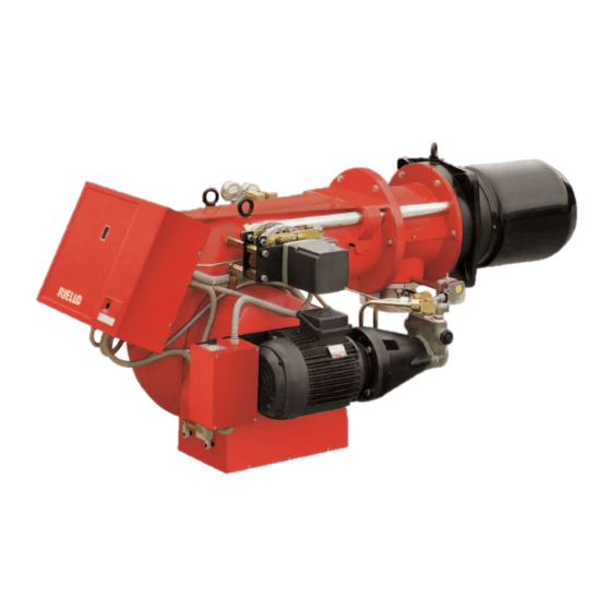
DONNÉES ÉLECTRIQUES Modele GI/EMME GI/EMME GI/EMME GI/EMME GI/EMME GI/EMME GI/EMME 1400 2000 2000 3000 3000 4500 4500 Codice 3486653-55 3487653-57 3487655-59 3488753-57 3488755-59 3489055-63 3489057-65 3486654-56 3487654-58 3487656-60 3488754-58 3488756-60 3489056-64 3489058-66 Alimentation electriques 3 ~ 230/400V +/-10% 50 Hz Moteur ventilateur IE2 tr/min 2920... - Seite 12 DESCRIZIONE BRUCIATORE (A) Modulatore di potenza (solo per versione modulante) Pressostato aria Asta comando farfalla gas Blocco relè motore ventilatore Morsettiera Passacavi Pulsante di sblocco apparecchiatura con segnalazione di blocco D1372 Asta di trascinamento testa Servomotore 10 Camma di regolazione aria 11 Pressostato gas di massima 12 Presa di pressione gas al manicotto 13 Regolatore gas...
- Seite 13 BRENNERBESCHREIBUNG (A) BURNER DESCRIPTION (A) DESCRIPTION BRULEUR (A) Leistungsmodulator Output modulation unit Regulateur de puissance (nur bei modulierendem Betrieb) (only on modulating version) (uniquement pour version modulante) Luftdruckwächter Air pressure switch Pressostat air Steuergestänge Gasdrossel Gas butterfly control rod Tige de commande papillon gaz Relais - Entriegelung Gebläsemotor Fan motor relay releaser Rearmement relais moteur ventilateur...
-
Seite 14: Installazione
CAMPI DI LAVORO (A) D1374 Il CAMPO DI LAVORO è stato ricavato alla temperatura ambiente di 20 °C ed alla pres- sione barometrica di 1000 mbar (circa 100 m s.l.m.). INSTALLAZIONE Tutte operazioni installazione, manutenzione e smontaggio devono assolutamente essere eseguite PERICOLO con rete elettrica staccata. -
Seite 15: Installation
FIRING RATES (A) PLAGES DE PUISSANCE (A) REGELBEREICHE (A) The FIRING RATE area values have been La PLAGE DE PUISSANCE a été calculée Der REGELBEREICH wurde bei einer obtained considering a surrounding tem- à une température ambiante de 20 °C et à Raumtemperatur von 20 °C und einem perature of 20°C and an atmospheric pres- une pression barométrique de 1000 mbars... -
Seite 16: Impianto Idraulico
IMPIANTO IDRAULICO Accertarsi, prima di mettere in funzionamento il bruciatore, che il tubo di ritorno non abbia occlusioni. impedimento provocherebbe rottura dell’organo tenuta della pompa. Non si deve superare la depressione max. di 0,45 bar (35 cm Hg). Oltre tale valore si ha liberazione di gas dal combustibile. -
Seite 17: Hydraulic System
HYDRAULIKANLAGE HYDRAULIC SYSTEM INSTALLATION HYDRAULIQUE Before placing the burner in S’assurer, avant de mettre en Vor Inbetriebnahme des Bren- operation, ensure that the return route le brûleur, que le tube de ners nachprüfen, dass line is open. retour ne soit pas obstrué. Rückflussrohr nicht verstopft Any obstruction may damage... - Seite 18 OTENZA ALL’ACCENSIONE DEL G 25 G 20 D1377 BRUCIATORE Secondo norma EN 676. Bruciatori con potenza MAX. oltre i 120 kW. L’accensione deve avvenire potenza ridotta rispetto alla potenza max. di funzionamento. Se la potenza all’accen- sione non supera i 120 kW nessun calcolo è...
-
Seite 19: Firing Output
ZÜNDLEISTUNG FIRING OUTPUT PUISSANCE A L’ALLUMAGE Nach Norm EN 676. According to regulation EN 676. Selon la norme EN 676. Brûleurs à puissance MAX au delà des Brenner mit Höchstleistung über 120 kW. Burners with max. output above 120 kW. Die Zündung hat bei einer verringerten Lei- 120 kW. - Seite 20 IMPIANTO ELETTRICO ESEGUITO IN FABBRICA / AVVIAMENTO DIRETTO WERKSEITIG AUSGEFÜHRTE ELEKTROANLAGE / DIREKTER MOTORSTART ELECTRICAL EQUIPMENT FACTORY - SET / DIRECT MOTOR STARTING INSTALLATION ELECTRIQUE REALISEE EN USINE / DEMARRAGE DIRECT DU MOTEUR GI/EMME 1400 - 2000 - 3000 Commutatore - Umschalter Selector switch - Commutateur D1403 D1399...
- Seite 21 IMPIANTO ELETTRICO ELEKTROANLAGE IMPIANTO ELETRICO ELEKTROANLAGE (Eseguito in fabbrica) (Werkseitig ausgeführt) SCHEMA (A) SCHEMA (A) Bruciatori GI/EMME 1400 - 2000 - 3000 Brenner GI/EMME 1400 - 2000 - 3000 con avviamento diretto del motore. mit direktem Motorstart SCHEMA (B) SCHEMA (B) Bruciatori GI/EMME 2000 - 3000 - 4500 Brenner GI/EMME 2000 - 3000 - 4500 con avviamento stella - triangolo del motore.
- Seite 22 SCHEMA (A) ALLACCIAMENTO ELETTRICO CON AVVIAMENTO MOTORE DIRETTO Allacciamento elettrico ai bruciatori ELEKTROANSCHLUß MIT DIREKTSCHALTUNG GI/EMME 1400 - 2000 - 3000 ELECTRICAL CONNECTION WITH DIRECT MOTOR STARTING • con avviamento motore diretto; BRANCHEMENT ELECTRIQUE AVEC DEMARRAGE MOTEUR DIRECT • con controllo tenuta valvole gas VPS. GI/EMME 1400 - 2000 - 3000 Il controllo tenuta valvole avviene subito prima di ogni avviamento del bruciatore.
- Seite 23 SCHEMA (A) LAYOUT (A) SCHEMA (A) Elektroanschluß der Brenner GI/EMME Branchement électrique brûleurs Electrical connection GI/EMME 1400 - 1400 -2000 - 3000 GI/EMME 1400 -2000 - 3000 2000 - 3000 • mit Direktschaltung; • avec démarrage moteur direct • with direct motor starting; •...
- Seite 24 SCHEMA (A) ALLACCIAMENTO RWF Allacciamento regolatore di potenza ANSCHLUß RWF RWF e relativa sonda ai bruciatori GI/ CONNECTION RWF EMME 1400 - 2000 - 3000 - 4500 (funzio- RACCORDEMENT RWF namento modulante). Tutte operazioni installazione, manutenzione e smontaggio devono assolutamente essere eseguite PERICOLO con rete elettrica staccata.
- Seite 25 SCHEMA (A) LAYOUT (A) SCHEMA (A) Anschluß des Leistungsreglers RWF und Connection of regulator RWF and related Raccordement régolateur de puissance RWF et sonde au porte - bornes bru- des entsprechenden Fühlers an die Bren- probe to GI/EMME 1400 - 2000 - 3000 - 4500 leurs GI/EMME 1400 - 2000 - 3000 - 4500 ner GI/EMME 1400 - 2000 - 3000 - 4500 burners (modulating operation).
- Seite 26 ORGANI DEL BRUCIATORE SERVOMOTORE tipo LANDIS REGOLATI IN FABBRICA STELLMOTOR typ LANDIS Nella generalità dei casi non necessitano SERVOMOTOR type LANDIS SERVOMOTEUR type LANDIS di ulteriori regolazioni: - servomotore - pompa - telesalvamotore / avviatore stella-trian- golo SERVOMOTORE (A) Il servomotore regola contemporanea- mente, tramite rinvii, portata e pressione dell’aria e portata del combustibile in uso.
- Seite 27 IM WERK EINGESTELLTE FACTORY - SET BURNER UNITS ORGANES DU BRÛLEUR A L’USINE BRENNERTEILE The following units do not generally require En général, les appareils suivants n’ont Folgende Teile müssen in der Regel nicht further adjustment: pas besoin d’autres réglages: nochmals eingestellt werden: - servomotor - servomoteur...
- Seite 28 UGELLI CONSIGLIATI (A) RELAZIONE INDICATIVA TRA: TIPO E PORTATA UGELLO IN (%) - PRESSIONE SUL RITORNO Scegliere l’ugello, con portata nominale ANNÄHERNDES ABHÄNGIGKEITSVERHÄLTNIS VON DÜSENTYP, DÜSENDURCHSATZ IN leggermente superiore a quella effettiva- (%) UND RÜCKLAUFDRUCK mente richiesta, fra i seguenti tipi: APPROXIMATE RATIO BETWEEN: NOZZLE DELIVERY AND TYPE (AS %) - RETURN PRESSURE RAPPORT INDICATIF ENTRE: LE TYPE ET LE DÉBIT DU GICLEUR (EN %) - PRESSION SUR - Fluidics...
- Seite 29 EMPFOHLENE DÜSEN (A) RECOMMENDED NOZZLES (A) GICLEURS CONSEILLES (A) Die Düse, deren Nenndurchsatz den erfor- Choisir le gicleur, entre les différents types Select the nozzle, with a delivery rating derlichen leicht überschreitet, kann unter suivants, avec un débit nominal légère- slightly higher than effectively required, folgenden Typen gewählt werden: ment supérieur au débit effectivement...
-
Seite 30: Regolazione Testa Di Combustione
REGOLAZIONE TESTA DI D1387 COMBUSTIONE La testa di combustione si muove contem- poraneamente all’eccentrico 8)(B)p.28, alle camme a profilo variabile e alla farfalla gas. Il posizionamento della testa è visibile sul cilindro 2)(B). I levismi di comando della testa vengono tarati in fabbrica per la corsa massima. -
Seite 31: Flammkopf - Einstellung
FLAMMKOPF - EINSTELLUNG COMBUSTION HEAD ADJUSTMENT RÉGLAGE DE LA TÊTE DE COMBUSTION Der Flammkopf bewegt sich gleichzeitig The combustion head moves simultane- La tête de combustion se déplace en mit dem Nocken 8)(B)S.28, den Nocken même temps que l’excentrique 8)(B)p.28, ously with cam 8)(B)p.28, the variable-pro- mit einstellbarem Profil und der Gasdros- que la came à... - Seite 32 REGOLAZIONE SERRANDA ARIA a regolazione della serranda dell’aria si attua agendo sulla camma a profilo varia- bile. Questa operazione va eseguita dopo D1389 aver regolato il variatore di pressione e la testa di combustione. A bruciatore acceso, togliere tensione al servomotore, staccando lo spinotto fast-on posto sulla mensola comandi elettrici, e svincolare il movimento premendo lo...
- Seite 33 LUFTKLAPPEN - EINSTELLUNG AIR DAMPER ADJUSTMENT REGLAGE DU VOLET D’AIR Die Einstellung der Luftklappe erfolgt Air damper adjustment is performed by Le réglage du volet de l’air s’effectue en durch Betätigung des Nockens mit einstell- acting on the variable profile cam. agissant sur la came à...
- Seite 34 REGOLAZIONI FUNZIONA- MENTO A GAS SFIATO DELL’ARIA (A) Si effettua aprendo l’apposita vite posta sul 1 - Vite / Schraube / Screw / Vis 2 - Attacco per misurazione pressione pressostato gas di minima montato sulla Druck - Meßanschluß rampa gas. Fitting for pressure measurement Prise pour mesure de la pression PRESSOSTATO GAS DI MINIMA (B)
-
Seite 35: Einstellung Für Gasbetrieb
EINSTELLUNG FÜR GASBETRIEB STARTING THE BURNER RÉGLAGE POUR FONCTIONNE- MENT AU GAZ ENTLÜFTUNG (A) VENTING THE GAS SUPPLY (A) Erfolgt, wenn man die Schraube am Min- EVACUATION DE L’AIR (A) This is done by removing the screw from destgasdruckwächter Gasarmatur On l’effectue en agissant sur la vis appro- the gas pressure switch, or the pressure herausdreht. - Seite 36 FUNZIONAMENTO BRUCIATORE (A) ACCENSIONE REGOLARE / ORDNUNGSGEMÄSSES ZÜNDEN NORMAL FIRING / ALLUMAGE REGULIER Blocco motore È provocato dal relè termico salvamotore in caso di sovraccarico o di mancanza di fase. SCHEMA FUNZIONAMENTO IDRAULICO Pressostato olio Determina il blocco del bruciatore in caso di eccessiva contropressione sulla linea di ritorno del combustibile.
- Seite 37 BRENNERBETRIEB (A) BURNER OPERATION (A) FONCTIONNEMENT BRULEUR (A) Motorstörabschaltung Motor lock Blocage moteur Verursacht durch das Wärmerelais des This is brought about by the overload cut- Il est provoqué par le relais thermique pro- Motorschutzschalters bei Überbelastung out thermic relay when a phase is missing. tège-moteur en cas de surchage ou oder Phasenausfall.
-
Seite 38: Pressostato Olio Di Massima
PRESSOSTATO OLIO DI MASSIMA Il pressostato olio di massima rileva la pressione immediatamente a valle del regolatore. E’ regolata in fabbrica ad una pressione di 3 bar. Se in funzionamento la pressione superasse il valore settato, l’apertura del contatto impedisce il funzio- namento del bruciatore , in alcuni casi mandandolo in sicurezza. - Seite 39 MAXIMAL-ÖLDRUCKWÄCHTER MAXIMUM OIL PRESSURE SWITCH PRESSOSTAT FIOUL SEUIL MAXIMUM Le pressostat de fioul seuil maximum Der Maximal-Öldruckwächter misst den The maximum oil pressure switch meas- détecte la pression immédiatement en aval Druck sofort hinter dem Regler. Er wird ures the pressure immediately down- du régulateur.
- Seite 40 RIELLO S.p.A. I-37045 Legnago (VR) Tel.: +39.0442.630111 http:// www.riello.it http:// www.riello.com Con riserva di modifiche - Änderungen vorbehalten! - Subject to modifications - Sous réserve de modifications...