Herunterladen Inhalt Inhalt Diese Seite drucken
Cembre HT-TRC2 Bedienungsanleitung

Cembre HT-TRC2 Bedienungsanleitung

Hydraulisches werkzeug

Werbung

Verfügbare Sprachen
  • DE

Verfügbare Sprachen

ENGLISH
OPERATION AND MAINTENANCE MANUAL ....................................6
FRANÇAIS
NOTICE D'UTILISATION ET ENTRETIEN ..............................................9
DEUTSCH
BEDIENUNGSANLEITUNG ................................................................... 12
ESPAÑOL
MANUAL DE USO Y MANTENIMIENTO ........................................... 15
ITALIANO
MANUALE D'USO E MANUTENZIONE ............................................. 18
1
HYDRAULIC TOOL
OUTIL HYDRAULIQUE
HYDRAULISCHES WERKZEUG
HERRAMIENTA HIDRÁULICA
UTENSILE OLEODINAMICO
HT-TRC HT-TRC2
Certified Quality
Certified Environmental
Management System
Management System
Certified Occupational
Health & Safety
Management System

Werbung

Inhaltsverzeichnis
loading

Inhaltszusammenfassung für Cembre HT-TRC2

  • Seite 1 Management System Health & Safety Management System HYDRAULIC TOOL OUTIL HYDRAULIQUE HYDRAULISCHES WERKZEUG HERRAMIENTA HIDRÁULICA UTENSILE OLEODINAMICO HT-TRC HT-TRC2 ENGLISH OPERATION AND MAINTENANCE MANUAL ........6 FRANÇAIS NOTICE D’UTILISATION ET ENTRETIEN ..........9 DEUTSCH BEDIENUNGSANLEITUNG ..............12 ESPAÑOL MANUAL DE USO Y MANTENIMIENTO ........... 15 ITALIANO MANUALE D’USO E MANUTENZIONE ..........
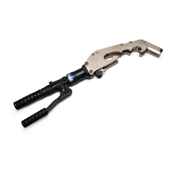
  • Seite 2 GUARD - PROTECTION - SCHUTZ - PROTECCION - PROTEZIONE HEAD - TÊTE - KOPF - CABEZA - TESTA INSERTING JAW - MÂCHOIRE D'INSERTION - MONTAGELASCHE - MORDAZA DE INSERCIÓN - GANASCIA DI INSERZIONE EXTRACTING JAW - MÂCHOIRE D’EXTRACTION - DEMONTAGEHEBEL - MORDAZA DE EXTRAC- CIÓN - GANASCIA DI ESTRAZIONE BODY - CORPS - KÖRPER - CUERPO - CORPO MOVEABLE HANDLE - BRAS MOBILE - BEWEGLICHER GRIFF - BRAZO MOVIL - MANICO MOBILE...
  • Seite 3 WARNING SYMBOLS - SYMBOLES D'AVERTISSEMENT - WARNSYMBOLE - SÍMBOLOS DE ADVERTENCIA - SIMBOLI DI AVVERTENZA – Before using the tool, carefully read the instructions in this manual. – Avant d'utiliser cet outil, lire attentivement les instructions de cette notice. – Vor Inbetriebnahme unbedingt die Bedienungsanleitung durchlesen. –...
  • Seite 4 FIG. / BILD 5 FIG. / BILD 6    FIG. / BILD 7 FIG. / BILD 8   ...
  • Seite 5 FIG. / BILD 9 FIG. / BILD 10 FIG. / BILD 11   FIG. / BILD 12...
  • Seite 6: General Characteristics

    Safety maximum pressure valve 2. INSTRUCTIONS FOR USE Do not use the tool for purposes other than those intended by Cembre. The operator should concentrate on the work being performed and be careful to maintain a balanced working position. 2.1 INSTALLING THE TEMPORAIL CONTACT Remove ballast from under the rail for 15-20 cm in and around the installation area (FIG.
  • Seite 7 To make sure the contact and the rail are matched exactly it is essential to operate the tool until the pressure relief valve clicks (CLICK) (FIG. 7). After the contact is installed, push down the pressure release lever (8) until the ram is fully retracted, then remove the tool from the rail.
  • Seite 8: Maintenance

    – Fit reservoir cap (11). i – Assemble main handle (7) to tool body. If the tool continues to malfunction, return the tool to Cembre for service/repair as detailed in § 5. 4.2) Oil top up Every six months check the oil level in the reservoir. If necessary, top up the oil level to the top lip of the reservoir and remove all air from the reservoir, see 4.1, points a, b, c, and e, finally, complete...
  • Seite 9: Caracteristiques Generales

    1. CARACTERISTIQUES GENERALES Domaine d'application: adapté à l’installation/retrait des contacts électriques Cembre "TEMPORAIL" sur la semelle des rails. Force nom. développée kN (US sh. ton) 50 (6) Pression nom. de travail bar (psi) 700 (10,000) Dimensions mm (inches) 715 x 177 x 70 (28.1 x 7 x 2.7)
  • Seite 10 Pour assurer le bon accouplage entre le contact et le rail, il est indispensable d’actionner l’outil jusqu’au déclic de la valve de surpression (CLICK) (FIG. 7). Une fois le contact installé, appuyer à fond sur le levier de déblocage pression (8) pour faire revenir complètement le piston puis, retirer l’outil du rail.
  • Seite 11: Entretien

    – Ensuite, remonter le bras principal (7). Dans l’éventuel cas où, malgré cette intervention, l’outil ne fonctionnerait pas correctement, il est recommandé de le retourner à Cembre pour une révision complète (voir § 5). 4.2) Complément d’huile La présence de bulles d’air est évitée en maintenant le réservoir d’huile toujours plein.
  • Seite 12: Allgemeine Eigenschaften

    1. ALLGEMEINE EIGENSCHAFTEN Anwendungsbereich Zur Montage und Demontage von Kontaktklemmen vom Typ Cembre "TEMPORAIL" am Schienenfuß. Nennpreßkraft kN (US sh. ton) 50 (6) Nennarbeitsdruck bar (psi) 700 (10,000) Abmessungen mm (inches) 715 x 177 x 70 (28.1 x 7 x 2.7)
  • Seite 13: Entfernen Die Kontaktklemme Temporail

    2.1.3) Befestigen die Kontaktklemme am Schienenfuß Betätigen Sie den beweglichen Griff weiter. Die Montagelasche (3) schiebt sich weiter nach vorne, die Kontaktklemme am Schienenfuß befestigt ist (BILD 7). Um sicherzustellen, dass die Kontaktklemme und Schiene perfekt miteinander verbunden sind, muss das Werkzeug unbedingt bis zum Reagieren des Überdruckventils betätigt werden, das an einem Klickgeräusch zu erkennen ist (CLICK) (BILD 7).
  • Seite 14: Wartung

    3.2) Lagerung Wenn das Werkzeug nicht benötigt wird, sollte es in der Segeltuchtasche gelagert werden, um es somit gegen Beschädi- gungen wie Stoß und Staub zu schützen. Die Segeltuchtasche (Typ CVB-029) hat die Abmessungen 700x200x40 mm (27.5x7.9x1.6 in.) und ein Gewicht von 400 g (0.88 lbs).
  • Seite 15: Características Generales

    1. CARACTERíSTICAS GENERALES Campo de aplicación: idónea para la instalación/extracción de los concatos eléctricos Cembre "TEMPORAIL" al patín de los carriles ferroviarios Fuerza nominal kN (US sh. ton) 50 (6) Presión nominal de trabajo bar (psi) 700 (10,000) Dimensiones mm (inches) 715 x 177 x 70 (28.1 x 7 x 2.7)
  • Seite 16 Para garantizar la correcta instalación del contacto sobre el patín es necesario accionar la herramienta hasta alcanzar la presión máxima y activar la válvula de seguridad au- tomática, se oyera un CLICK (FIG. 7). Después la instalación del contacto, empujar la palanca de desbloqueo presión (8) para obtener el retorno completo del pistón, luego remover la herramienta del carril.
  • Seite 17: Mantenimiento

    – Vuelva a ensamblar el brazo fijo (7). En el caso inusual, de que tras estas operaciones, la herramienta no funcionara correctamente, le sugerimos que devuelva la herramienta a Cembre para su revisión (ver Epig. 5). 4.2) Rellenado de aceite La presencia de burbujas de aire, se evita con el depósito de aceite completamente lleno.
  • Seite 18: Caratteristiche Generali

    1. CARATTERISTICHE GENERALI Campo di applicazione adatto all'installazione/rimozione dei contatti elettrici Cembre "TEMPORAIL" sulla suola delle rotaie ferroviarie. Forza nom. di compressione kN (US sh. ton) 50 (6) Pressione nom. di esercizio bar (psi) 700 (10,000) Dimensioni mm (inches) 715 x 177 x 70 (28.1 x 7 x 2.7)
  • Seite 19 Per garantire l'esatto accoppiamentro tra il contatto e la rotaia è indispensabile azionare l'utensile fino all'intervento della valvola di massima pressione, della quale si avvertirà lo scatto (CLICK) (FIG. 7). Dopo l'installazione del contatto, premere a fondo la leva sblocco pressione (8) per ottenere il ritorno completo del pistone, quindi rimuovere l'utensile dalla rotaia.
  • Seite 20: Manutenzione

    Nel caso eccezionale che l’utensile, anche dopo queste operazioni di manutenzione, non funzio- nasse correttamente (il pistone non avanza o pulsa) è consigliabile contattare il più vicino Agente Cembre per la sua completa revisione (vedi § 5). 4.2) Rabbocco dell’olio Il serbatoio dell’olio deve essere sempre pieno;...
  • Seite 21 The guarantee is void if parts used are not Cembre original spares. La garantie perd tout effet en cas d'emploi de piéces détachées différentes des pièces d'origine Cembre. Die Garantie verfällt, wenn nicht Originalteile aus dem Hause Cembre in das Gerät eingebaut werden.
  • Seite 22 6232730 METAL LABEL / PLAQUETTE / TYPENSCHILD / TARJETA / TARGHETTA TG 0974 HT-TRC 6232827 METAL LABEL / PLAQUETTE / TYPENSCHILD / TARJETA / TARGHETTA TG 1070 HT-TRC2 6650118 RIVET / RIVET / NIET / PASADOR / RIVETTO ø2,5x3,5 6180345 SELF-LOCK NUT / ECROU AUTO-BLOQ.
  • Seite 24: Einsendung An Cembre Zur Überprüfung

    Centre; if possible, attach a copy of the Test Certificate supplied by Cembre together with the tool or fill in and attach the form available in the “ASSISTANCE”...

Diese Anleitung auch für:

Ht-trc

Inhaltsverzeichnis