Viessmann 5104 Gebrauchsanleitung
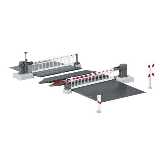
Bahnschranke mit behang
vollautomatisch, mit zubehör
Vorschau ausblenden
Andere Handbücher für 5104:
- Bedienungsanleitung (16 Seiten) ,
- Bedienungsanleitung (16 Seiten)
Inhaltsverzeichnis
Gebrauchsanleitung
Manual
5104
Bahnschranke mit Behang
vollautomatisch, mit Zubehör
Automatic Crossing Barrier
with accessories
1.
Wichtige Hinweise ......................................
2.
Einleitung ...................................................
3.
Inhalt ..........................................................
4.
Funktionskontrolle ......................................
5.
Montage .....................................................
6.
Anschluss ...................................................
7.
Anschluss von Zubehör ..............................
8.
Digitalbetrieb
9
Montage der Verkehrszeichen ....................
10. Technische Daten ......................................
1.
Important Information .................................
2.
Introduction ................................................
3.
Content ......................................................
4.
Function Check ..........................................
5.
Mounting .....................................................
6.
Electrical Connections .................................
7.
Connecting Accessories..............................
8.
Digital Control ............................................
9. Installing Traffic Signs
10. Technical Data ...........................................
..................................
............................ 1 6
2
2
5
5
6
8
12
12
16
16
2
2
5
5
AC
5
~
7
DC
=
13
14
16
MM
DCC
Inhaltsverzeichnis

Verwandte Anleitungen für Viessmann 5104


Inhaltszusammenfassung für Viessmann 5104
-
Seite 1: Inhaltsverzeichnis
Gebrauchsanleitung Manual 5104 Bahnschranke mit Behang vollautomatisch, mit Zubehör Automatic Crossing Barrier with accessories Wichtige Hinweise ........Einleitung ........... Inhalt ............Funktionskontrolle ........Montage ............. Anschluss ........... Anschluss von Zubehör ......Digitalbetrieb ........Montage der Verkehrszeichen ....10. Technische Daten ........ -
Seite 2: Wichtige Hinweise
1. Wichtige Hinweise 1. Important Information Lesen Sie vor der ersten Benutzung des Pro- Please read this manual prior to first use of the duktes bzw. dessen Einbau diese Anleitung voll- product resp. its installation! Keep this manual. It is ständig und aufmerksam durch. - Seite 3 Unter-oder Überführungen ersetzt- werden Model The Viessmann model of a crossing barrier truly Modell simulates the prototypical situation and is an eye Dieses Viessmann-Modell einer Bahnschranke catcher on any model train layout. The two barri- gibt die Vorbildsituation originalgetreu wieder.
- Seite 4 Pos. Bezeichnung / Description Stück Schranke mit Antrieb und Decoder / Barrier with driving mechanism and decoder Schranke mit Antrieb / Barrier with driving mechanism Verkehrsschild mit Mast / Traffic sign with pole Andreaskreuz mit Mast / St.Andrew‘s cross with pole Warnbaken mit Mast / Range pole Rampe / Ramp Rampenfuß...
-
Seite 5: Funktionskontrolle
Connect the yellow and the brown wires to the an den Wechselspannungsausgang (16 V) eines 16V AC output of your transformer – e.g.: Modellbahntransformators – z. B. Viessmann Viessmann 5200. 5200 – an. Der Trafo muss während des Anschlie- Make sure that the transformer is switched off ßens ausgeschaltet sein. - Seite 6 sorgen. Hierbei sollten Sie die Sockel der down the base of the barrier form above. Bahnschranke von oben festhalten. 5. Insert the barrier supports into the appropri- 5. Stecken Sie die Widerlager in die entspre- ate holes. chenden Bohrungen ein. 6. Glue the infill (8) or (9) onto the sleepers be- 6.
-
Seite 7: Electrical Connections
Betrieb zu realisieren: • With track contacts (Reed contacts & mag- • Mit Schaltkontakten (Reed-Kontakte & nets e.g.: Viessmann 6840 & 6841) Magnete z. B.: Viessmann 6840 & 6841) • With switching tracks (activated by each • Mit Schaltgleisen wheel resp. axle) •... -
Seite 8: Ansteuerung Mit Schaltkontakten (Reed)
5552 schneller und in der anderen langsamer senken according to Fig. 6. und heben möchten, schließen Sie zusätzlich ein elektronisches Relais Viessmann 5552 gemäß Abb. 6 Fig. 6 * optional zum Soundmodul und Andreaskreuz To the soundmodule and St. - Seite 9 A train travelling from left to right first activates the Richtungen befahren wird (Abb 9), muss mit- contact on the far left and sets the directional relay tels eines elektronischen Relais (z.B.: Viessmann to the position for this direction. Thus the follow- 5552) die Zuordnung der Kontakte angepasst ing contact on the left is connected via the relay to werden.
- Seite 10 (z.B.: Viessmann 5552) angeschlossen werden. sing. Damit wird sichergestellt, dass die Schranken nur The correct wiring of the decoder 5104 for the bar- dann geöffnet werden, wenn bei sich kreuzenden riers is shown in per Fig. 7 except for substituting...
-
Seite 11: Ansteuerung Über Gleisbesetztmelder
Öffnen der ting a sound module for a signal bell. How to wire Schranken automatisch verhindert solange sich the Viessmann sound module 5556 is shown in ein Zug im Bereich des Bahnübergangs befindet. Fig. 11. -
Seite 12: Anschluss Von Zubehör
Soundmoduls für das Läutewerk nect the blinking module 5065 for the warning vorbereitet. lights of the St. Andrew´s crosses in parallel to Der Anschluss des Viessmann Soundmoduls the sound module. 5556 ist in Abbildung 11 dargestellt. Please note that the green wire must be con- Blinklicht für beleuchtete nected via a 330 Ohm/0.25 Watt resistor to the... -
Seite 13: Digital Operation
Der integrierte Digitaldecoder unterstützt die Formate DCC und MM (Märklin/Motorola) und er- Assigning an address: möglicht die Steuerung über eine geeignete Digi- talzentrale (z. B.: Viessmann Commander). For digital control of this model you must first as- sign a digital address. Der Decoder empfängt die Digitalbefehle über die Versorgungsleitungen während die Steuerlei- Now the model is ready for operation with the newly assigned address. Should you wish to... -
Seite 14: Digital Control
Command station or 16 V ~ z.B. 5200 or 16 V = (brown is positive) Blinkgerät Blinking module 16 V ~ Schaltdekoder viessmann Switching decoder 4-fach-Blinkgerät 5065 z.B. 5213, 5209 Commander zu Andreaskreuzen To the St. Andrew’s crosses rot / red... -
Seite 15: Anschluss Der Blinklichter Für Beleuchtete Andreaskreuze
5065 für die Andreaskreuze parallel zum wired to the output of a switching decoder (e.g.: Soundmodul 5556 gemäß Abb. 11 angeschlos- Viessmann 5213 for MM or 5209 for DCC) and sen werden. the blinking module (Viessmann 5065) as shown Die Blinklichter können im Digitalbetrieb aber... -
Seite 16: Technische Daten
Schenkel nach unten zeigten. 3. Drill 4mm holes as shown in Fig. 7 at the posi- tions desired and install the signs in the correct 3. Bohren Sie an den dafür vorgesehenen Stellen sequence (see Figure 13). Löcher mit 4mm Durchmesser und montieren Sie die Schilder in der richtigen Reihenfolge (si- 4.