Lenze EMF2180IB Montageanleitung
Ethernetcan
Vorschau ausblenden
Andere Handbücher für EMF2180IB:
- Montageanleitung (150 Seiten) ,
- Kommunikationshandbuch (70 Seiten)

Verwandte Anleitungen für Lenze EMF2180IB


Inhaltszusammenfassung für Lenze EMF2180IB
- Seite 1 L-force Communication EDKMF2180 .AEk Montageanleitung Mounting Instructions Instructions de montage Instrucciones para el montaje Istruzioni per il montaggio EthernetCAN EMF2180IB Kommunikationsbaugruppe Communication module Module de communication Módulo de comunicación Modulo di comunicazione ...
- Seite 2 Lesen Sie zuerst diese Anleitung, bevor Sie mit den Arbeiten beginnen! Beachten Sie die enthaltenen Sicherheitshinweise. Please read these instructions before you start working! Follow the enclosed safety instructions. Veuillez lire attentivement cette documentation avant toute action ! Les consignes de sécurité...
- Seite 3 2180FEW001D...
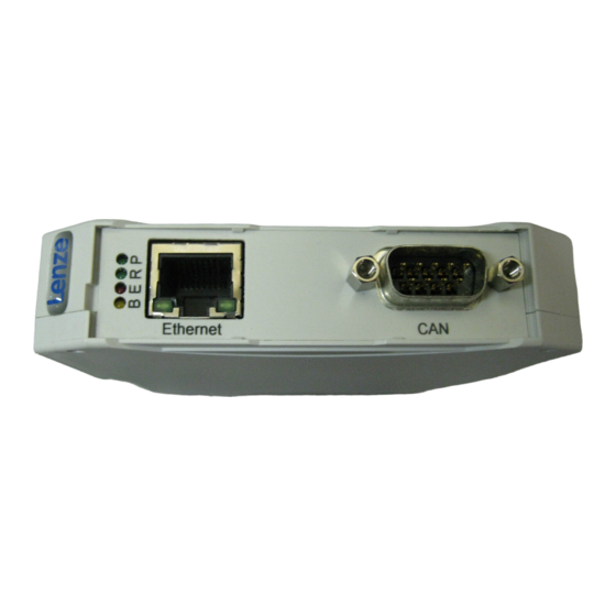
- Seite 4 Legende zur Abbildung auf der Ausklappseite Pos. Beschreibung Ausführliche Information Ethernet-Anschluss 24 Buchse RJ45 CAN-Anschluss 21 9-polige Sub-D-Buchse Anschluss für Spannungsversorgung 26 4-polige Steckerleiste mit Federkraftanschluss PE-Anschluss Die gesteckte Kommunikationsbaugruppe ist automatisch mit der Hut- schiene verbunden. Die Hutschiene muss mit PE verbunden sein! ...
-
Seite 5: Inhaltsverzeichnis
Inhalt Über diese Dokumentation ......... . Verwendete Konventionen . -
Seite 6: Über Diese Dokumentation
Diese Dokumentation richtet sich an Personen, die die Vernetzung und Fernwartung einer Maschine projektieren, installieren, in Betrieb nehmen und warten. Tipp! Dokumentationen und Software-Updates zu weiteren Lenze Produkten finden Sie im Internet im Bereich ”Services & Downloads” unter http://www.Lenze.com ... -
Seite 7: Verwendete Konventionen
Über diese Dokumentation Verwendete Konventionen Verwendete Konventionen Diese Dokumentation verwendet folgende Konventionen zur Unterscheidung verschiede- ner Arten von Information: Informationsart Auszeichnung Beispiele/Hinweise Zahlenschreibweise Dezimaltrennzeichen Punkt Es wird generell der Dezimalpunkt verwendet. Beispiel: 1234.56 Symbole Seitenverweis Verweis auf eine andere Seite mit zu- sätzlichen Informationen ... -
Seite 8: Verwendete Hinweise
Über diese Dokumentation Verwendete Hinweise Verwendete Hinweise Um auf Gefahren und wichtige Informationen hinzuweisen, werden in dieser Dokumenta- tion folgende Piktogramme und Signalwörter verwendet: Sicherheitshinweise Aufbau der Sicherheitshinweise: Gefahr! (kennzeichnet die Art und die Schwere der Gefahr) Hinweistext (beschreibt die Gefahr und gibt Hinweise, wie sie vermieden werden kann) Piktogramm und Signalwort Bedeutung Gefahr von Personenschäden durch gefährliche elektri-... - Seite 9 Über diese Dokumentation Verwendete Hinweise Anwendungshinweise Piktogramm und Signalwort Bedeutung Wichtiger Hinweis für die störungsfreie Funktion Hinweis! Nützlicher Tipp für die einfache Handhabung Tipp! Verweis auf andere Dokumentation EDKMF2180 DE/EN/FR/ES/IT 3.0...
-
Seite 10: Sicherheitshinweise
Sicherheitshinweise Sicherheitshinweise Gefahr! Unsachgemäßer Umgang mit der Kommunikationsbaugruppe und dem Grundgerät kann schwere Personenschäden und Sachschäden verursachen. Beachten Sie die in der Dokumentation zum Grundgerät enthaltenen Sicherheitshinweise und Restgefahren. Stop! Elektrostatische Entladung Durch elektrostatische Entladung können elektronische Bauteile innerhalb der Kommunikationsbaugruppe beschädigt oder zerstört werden. -
Seite 11: Produktbeschreibung
Produktbeschreibung Funktion Die Kommunikationsbaugruppe dient mittels Fernwartung zur Parametrierung bzw. Pro- grammierung und Inbetriebnahme der einsetzbaren Geräte. Bestimmungsgemäße Verwendung Die Kommunikationsbaugruppe ist mit folgenden Lenze-Geräten einsetzbar: ƒ Servo Drives 9400 ƒ Inverter Drives 8400 ƒ Servo-Umrichter 9300 ƒ 9300 vector ƒ... -
Seite 12: Identifikation
Produktbeschreibung Identifikation Identifikation 2180FEW099 Typenschlüssel 33.2180IB Gerätereihe Hardwarestand Softwarestand EDKMF2180 DE/EN/FR/ES/IT 3.0... -
Seite 13: Technische Daten
Technische Daten Allgemeine Daten und Einsatzbedingungen Technische Daten Allgemeine Daten und Einsatzbedingungen Bereich Werte Bestell-Bezeichnung EMF2180IB Kommunikationsmedien (An- CAN (DIN ISO 11898) lage) Ethernet (100 Base TX, IEEE802.3u) Anzahl Teilnehmer am CAN-Bus Max. 100 Übertragungsrate bei Kommunikation über CAN – 20 kBit/s –... -
Seite 14: Technische Daten Schutzisolierung
Technische Daten Schutzisolierung Schutzisolierung 2180FEW001F Anschluss Art der Isolierung (nach EN 61800-5-1) Ethernet Betriebsisolierung CAN-Bus Betriebsisolierung Spannungsversorgung Keine Isolierung EDKMF2180 DE/EN/FR/ES/IT 3.0... -
Seite 15: Abmessungen
Technische Daten Abmessungen Abmessungen 2180FEW001B 117 mm 99 mm 22.5 mm EDKMF2180 DE/EN/FR/ES/IT 3.0... -
Seite 16: Mechanische Installation
Mechanische Installation Mechanische Installation Montage 2181FEW002B EDKMF2180 DE/EN/FR/ES/IT 3.0... - Seite 17 Mechanische Installation Demontage 2181FEW001E EDKMF2180 DE/EN/FR/ES/IT 3.0...
-
Seite 18: Elektrische Installation
Elektrische Installation Elektrische Installation 2180FEW008 Installationsschritte Schritt Tätigkeit Anschluss Zusätzliche Informa- tion (siehe Grafik) Verbindung zum CAN-Bus herstellen: 21 Sub-D-Stecker (”EWZ0046”, siehe Zubehör) in die Kommunikationsbaugruppe stecken. Folgende Komponenten über Ethernet mit- 24 einander verbinden: Kommunikationsbaugruppe Servo Drives 9400 weitere Ethernet-Teilnehmer Spannungsversorgung an die Steckerleiste... -
Seite 19: Umgang Mit Steckerleisten
Elektrische Installation Umgang mit Steckerleisten Umgang mit Steckerleisten Stop! Um Steckerleisten und Kontakte nicht zu beschädigen: Steckerleisten nur aufstecken / abziehen wenn der Antriebsregler vom ƒ Netz getrennt ist. Steckerleisten erst verdrahten, dann aufstecken. ƒ Nicht belegte Steckerleisten ebenfalls aufstecken. ƒ... -
Seite 20: Emv-Gerechte Verdrahtung
Elektrische Installation EMV-gerechte Verdrahtung EMV-gerechte Verdrahtung Für eine EMV-gerechte Verdrahtung beachten Sie folgende Punkte: Hinweis! Steuer-/Datenleitungen getrennt von Motorleitungen verlegen. ƒ Legen Sie die Schirme der Steuer-/Datenleitungen bei digitalen Signalen ƒ beidseitig auf. Zur Vermeidung von Potenzialdifferenzen zwischen den ƒ... -
Seite 21: Systembus (Can) Anschließen
Elektrische Installation Systembus (CAN) anschließen Systembus (CAN) anschließen 2180FEW001K Belegung der Sub-D-Steckerleiste Ansicht Belegung 1, 4, 5, 6, 8, 9 CAN-LO CAN-GND CAN-HI EDKMF2180 DE/EN/FR/ES/IT 3.0... - Seite 22 Elektrische Installation Systembus (CAN) anschließen Der CAN-Bus muss durch Widerstände (120 Ω) zwischen CAN-LOW und CAN-HIGH abge- schlossen sein. Der Sub-D-Stecker mit integriertem Abschlusswiderstand (Bestell-Nr. EWZ0046, nicht im Lieferumfang enthalten) entspricht der Empfehlung DS 102-1 von CiA. 2181FEW004 Spezifikation des Übertragungskabels Wir empfehlen CAN-Kabel nach ISO 11898-2 zu verwenden: CAN-Kabel nach ISO 11898-2 Kabeltyp...
- Seite 23 Elektrische Installation Systembus (CAN) anschließen Busleitungslänge Halten Sie die zulässigen Leitungslängen unbedingt ein. 1. Überprüfen Sie die Einhaltung der Gesamt-Leitungslänge in Tab. 1. Durch die Übertragungsrate ist die Gesamt-Leitungslänge festgelegt. Übertragungsrate [kBit/s] Max. Buslänge [m] 3600 1400 1000 Tab. 1 Gesamt-Leitungslänge 2.
-
Seite 24: Ethernet-Anschluss
Elektrische Installation Ethernet-Anschluss Ethernet-Anschluss 2181FEW004A Spezifikation des Übertragungskabels Hinweis! Verwenden Sie ausschließlich Kabel, die den aufgeführten Spezifikationen entsprechen. Spezifikation des Ethernet-Kabels Ethernet-Standard Standard Ethernet (nach IEEE 802.3), 100Base-TX (Fast Ethernet) Kabeltyp S/FTP (Screened Foiled Twisted Pair, ISO/IEC 11801 oder EN 50173), CAT 5e Dämpfung 23.2 dB (bei 100 MHz und je 100 m) - Seite 25 Elektrische Installation Ethernet-Anschluss Pin-Belegung 100BaseTX - CrossOver Cable 100BaseTX - Standard Patch Cable E94YCEI002 Verwendung der Kabel ƒ Das ”100BaseTX - CrossOver Cable” wird bei direkter Kopplung von PC und der Kommunikationsbaugruppe verwendet. ƒ Das ”100BaseTX - Standard Patch Cable” wird bei Verwendung von Hubs und Switches eingesetzt.
-
Seite 26: Spannungsversorgung
Elektrische Installation Spannungsversorgung Spannungsversorgung Daten der Anschlussklemmen 2181FEW001G Daten der Anschlussklemmen Elektrischer An- Steckerleiste mit Federkraftanschluss schluss Anschlussmöglichkei- starr: 2.5 mm (AWG 12) flexibel: ohne Aderendhülse 2.5 mm (AWG 12) mit Aderendhülse, ohne Kunststoffhülse 2.5 mm (AWG 12) mit Aderendhülse, mit Kunststoffhülse 2.5 mm (AWG 12) Abisolierlänge... -
Seite 27: Inbetriebnahme
Inbetriebnahme Vor dem ersten Einschalten Inbetriebnahme Vor dem ersten Einschalten Stop! Überprüfen Sie vor dem Einschalten der Netzspannung die gesamte Verdrahtung auf Vollständigkeit, Kurzschluss und Erdschluss. Weiterführende Informationen zur Inbetriebnahme dieser Kommunikationsbaugruppe finden Sie im Kommunikationshandbuch Fernwartung. EDKMF2180 DE/EN/FR/ES/IT 3.0... -
Seite 28: Diagnose
Diagnose LED-Statusanzeigen Diagnose LED-Statusanzeigen 2180FEW001H Pos. Farbe Zustand Beschreibung gelb Übertragungsrate: 10 MBit/s Übertragungsrate: 100 MBit/s blinkt Die IP-Adresse der Baugruppe ist noch nicht zuge- ordnet; sie wird momentan ermittelt. siehe 29 ERR-LED grün RUN-LED grün 2180 EthernetCAN wird mit Spannung versorgt. ... - Seite 29 Diagnose LED-Statusanzeigen Pos. Farbe / Zustand Beschreibung Verbindung zum Master nicht aufgebaut. grün CANopen Zustand (” ”) CANopen Fehler (” ”) : Bus Off blinkt schnell (flackern) Automatische Übertragungsratenerkennung ist aktiv. blinkt (grün) im 0.2 s-Takt : Pre-Operational, : keine blinkt (grün) im 0.2 s-Takt : Pre-Operational,...
- Seite 30 Legend for fold-out page Pos. Description Detailed information Ethernet connection 50 RJ45 socket CAN connection 47 9-pin Sub-D socket Connection for voltage supply 52 4-pin plug connector with spring connection PE connection The plugged communication module is automatically connected to the DIN rail.
- Seite 31 Contents About this documentation ......... . . Conventions used .
-
Seite 32: About This Documentation
This documentation addresses to persons who project, install, commission, and maintain the networking and remote maintenance of a machine. Tip! Documentation and software updates for further Lenze products can be found on the Internet in the ”Services & Downloads” area under http://www.Lenze.com ... -
Seite 33: Conventions Used
About this documentation Conventions used Conventions used This documentation uses the following conventions to distinguish between different types of information: Type of information Identification Examples/notes Numbers Decimal separator Point The decimal point is used throughout this documentation. Example: 1234.56 Symbols Page reference ... -
Seite 34: Notes Used
About this documentation Notes used Notes used The following pictographs and signal words are used in this documentation to indicate dangers and important information: Safety instructions Structure of safety instructions: Danger! (characterises the type and severity of danger) Note (describes the danger and gives information about how to prevent dangerous situations) Pictograph and signal word... - Seite 35 About this documentation Notes used Application notes Pictograph and signal word Meaning Important note to ensure troublefree operation Note! Useful tip for simple handling Tip! Reference to another documentation EDKMF2180 DE/EN/FR/ES/IT 3.0...
-
Seite 36: Safety Instructions
Safety instructions Safety instructions Danger! Inappropriate handling of the communication module and the basic device can cause serious injuries to persons and damage to material assets. Observe the safety instructions and residual hazards described in the documentation for the standard device. ... -
Seite 37: Product Description
The communication module is used for setting parameters during remote maintenance or programming and commissioning the usable devices: Application as directed The communication module can be used with the following Lenze devices: ƒ Servo Drives 9400 ƒ Inverter Drives 8400 ƒ... -
Seite 38: Identification
Product description Identification Identification 2180FEW099 Type code 33.2180IB Device series Hardware version Software version EDKMF2180 DE/EN/FR/ES/IT 3.0... -
Seite 39: Technical Data
Technical data General data and operating conditions Technical data General data and operating conditions Range Values Order designation EMF2180IB Communication media (system) CAN (DIN ISO 11898) Ethernet (100 Base TX, IEEE802.3u) Number of nodes at the CAN Max. 100 Baud rate when communicating via CAN –... -
Seite 40: Protective Insulation
Technical data Protective insulation Protective insulation 2180FEW001F Terminal Type of insulation (according to EN 61800-5-1) Ethernet Functional insulation CAN bus Functional insulation Voltage supply No insulation EDKMF2180 DE/EN/FR/ES/IT 3.0... -
Seite 41: Dimensions
Technical data Dimensions Dimensions 2180FEW001B 117 mm 99 mm 22.5 mm EDKMF2180 DE/EN/FR/ES/IT 3.0... -
Seite 42: Mechanical Installation
Mechanical installation Mechanical installation Mounting 2181FEW002B EDKMF2180 DE/EN/FR/ES/IT 3.0... - Seite 43 Mechanical installation Dismounting 2181FEW001E EDKMF2180 DE/EN/FR/ES/IT 3.0...
-
Seite 44: Electrical Installation
Electrical installation Electrical installation 2180FEW008 Installation steps Step Activity Terminal Additional information (see graphic) Establish a connection to the CAN bus: 47 Plug the Sub-D plug (”EWZ0046”, see accessories) into the communication module. Connect the following components via 50 Ethernet with each other: ... -
Seite 45: Use Of Plug Connectors
Electrical installation Use of plug connectors Use of plug connectors Stop! Observe the following to prevent any damage to plug connectors and contacts: Only pug in / unplug the plug connectors when the controller is ƒ disconnected from the mains. Wire the plug connectors before plugging them in. -
Seite 46: Wiring According To Emc
Electrical installation Wiring according to EMC Wiring according to EMC For wiring according to EMC requirements observe the following points: Note! Separate control cables/data lines from motor cables. ƒ Connect the shields of control cables/data lines at both ends in the case of ƒ... -
Seite 47: Connection Of System Bus (Can)
Electrical installation Connection of system bus (CAN) Connection of system bus (CAN) 2180FEW001K Assignment of the Sub-D plug connector View Assignment 1, 4, 5, 6, 8, 9 CAN-LO CAN-GND CAN-HI EDKMF2180 DE/EN/FR/ES/IT 3.0... - Seite 48 Electrical installation Connection of system bus (CAN) Between CAN_LOW and CAN-HIGH the CAN bus has to be terminated by resistors (120 Ω). The Sub-D plug with an integrated terminating resistor (order no. EWZ0046, not included in the scope of supply) complies with the recommendation DS 102-1 of CiA. 2181FEW004 Specification of the transmission cable We recommend the use of CAN cables in accordance with ISO 11898-2:...
- Seite 49 Electrical installation Connection of system bus (CAN) Bus cable length It is absolutely necessary to comply with the permissible cable lengths. 1. Check the compliance with the total cable length in Tab. 1. The total cable length is determined by the baud rate. Baud rate [kbit/s] Max.
-
Seite 50: Ethernet Connection
Electrical installation Ethernet connection Ethernet connection 2181FEW004A Specification of the transmission cable Note! Only use cables complying with the below specifications. Specification of the Ethernet cable Ethernet standard Standard Ethernet (in accordance with IEEE 802.3), 100Base-TX (Fast Ethernet) Cable type S/FTP (Screened Foiled Twisted Pair, ISO/IEC 11801 or EN 50173), CAT 5e Damping... - Seite 51 Electrical installation Ethernet connection Pin assignment 100BaseTX - CrossOver Cable 100BaseTX - Standard Patch Cable E94YCEI002 Use of cables ƒ The ”100BaseTX - CrossOver Cable” is used for direct coupling of PC and communication module. ƒ The ”100BaseTX - Standard Patch Cable” is used in conjunction with hubs and switches.
-
Seite 52: Voltage Supply
Electrical installation Voltage supply Voltage supply Terminal data 2181FEW001G Terminal data Electrical connection Plug connector with spring connection Possible connections rigid: 2.5 mm (AWG 12) flexible: without wire end ferrule 2.5 mm (AWG 12) with wire end ferrule, without plastic sleeve 2.5 mm (AWG 12) with wire end ferrule, with plastic sleeve... -
Seite 53: Commissioning
Commissioning Before switching on Commissioning Before switching on Stop! Prior to switching on the mains voltage, check the wiring for completeness, short-circuit and earth fault. Further information on how to commission this communication module can be found in the maintenance communication manual. ... -
Seite 54: Diagnostics
Diagnostics LED status displays Diagnostics LED status displays 2180FEW001H Pos. Colour State Description Yellow Baud rate: 10 Mbits/s Baud rate: 100 Mbits/s Blinking The IP address of the module is not assigned yet; it is currently being detected. See 55 ERR LED ... - Seite 55 Diagnostics LED status displays Pos. Colour / status Description Connection to master not established. green CANopen status (” ”) CANopen error (” ”) : Bus off blinking fast (jittering) Automatic baud rate recognition is active. blinking (green) every 0.2 s : Pre-Operational, : None blinking (green) every 0.2 s...
- Seite 56 Légende de l’illustration de la page dépliante Pos. Description Informations détaillées Raccordement Ethernet 76 Prise RJ45 Raccordement CAN 73 Connecteur Sub-D femelle 9 broches Raccordement de l’alimentation 78 Bornier à lame ressort 4 bornes Raccordement PE Le module de communication enfiché...
- Seite 57 Sommaire Présentation du document ......... . . Conventions utilisées .
-
Seite 58: Présentation Du Document
Conseil ! Les mises à jour de logiciels et les documentations relatives aux produits Lenze sont disponibles dans la zone ”Téléchargements” du site Internet : http://www.Lenze.com ... -
Seite 59: Conventions Utilisées
Présentation du document Conventions utilisées Conventions utilisées Pour faire la distinction entre différents types d’informations, ce document utilise les conventions suivantes : Type d’information Marquage Exemples/remarques Représentation des chiffres Séparateur décimal Point Le point décimal est généralement utilisé. Exemple : 1234.56 Symboles Renvoi à... -
Seite 60: Consignes Utilisées
Présentation du document Consignes utilisées Consignes utilisées Pour indiquer des risques et des informations importantes, la présente documentation utilise les mots et symboles suivants : Consignes de sécurité Présentation des consignes de sécurité Danger ! (Le pictogramme indique le type de risque.) Explication (L’explication décrit le risque et les moyens de l’éviter.) Pictogramme et mot associé... -
Seite 61: Remarque Importante
Présentation du document Consignes utilisées Consignes d’utilisation Pictogramme et mot associé Explication Remarque Remarque importante pour assurer un fonctionnement correct importante ! Conseil utile pour faciliter la mise en oeuvre Conseil ! Référence à une autre documentation ... -
Seite 62: Consignes De Sécurité
Consignes de sécurité Consignes de sécurité Danger ! Toute utilisation non conforme à la fonction du module de communication et de l’appareil de base risque d’entraîner des dommages corporels et matériels graves. Tenir compte des consignes de sécurité et des dangers résiduels énoncés dans la documentation de l’appareil de base. -
Seite 63: Description Du Produit
Le module de communication est destiné au paramétrage / à la programmation et à la mise en service à distance des appareils compatibles. Utilisation conforme à la fonction Le module de communication est compatible avec les appareils Lenze ci-dessous : ƒ Servo Drives 9400 ƒ Inverter Drives 8400 ƒ... -
Seite 64: Identification
Description du produit Identification Identification 2180FEW099 Codification des types 33.2180IB Série d’appareils Version matérielle Version logicielle EDKMF2180 DE/EN/FR/ES/IT 3.0... -
Seite 65: Spécifications Techniques
Spécifications techniques Caractéristiques générales et conditions d’utilisation Spécifications techniques Caractéristiques générales et conditions d’utilisation Domaine Valeurs Réf. de commande EMF2180IB Support de communication CAN (DIN ISO 11898) (installation) Ethernet (100 Base TX, IEEE802.3u) Nombre de participants au bus 100 max. -
Seite 66: Isolement De Protection
Spécifications techniques Isolement de protection Isolement de protection 2180FEW001F Raccordement Type d’isolement (selon EN 61800-5-1) Ethernet Isolement fonctionnel Bus CAN Isolement fonctionnel Alimentation Pas d’isolement EDKMF2180 DE/EN/FR/ES/IT 3.0... -
Seite 67: Encombrements
Spécifications techniques Encombrements Encombrements 2180FEW001B 117 mm 99 mm 22.5 mm EDKMF2180 DE/EN/FR/ES/IT 3.0... -
Seite 68: Installation Mécanique
Installation mécanique Installation mécanique Montage 2181FEW002B EDKMF2180 DE/EN/FR/ES/IT 3.0... - Seite 69 Installation mécanique Démontage 2181FEW001E EDKMF2180 DE/EN/FR/ES/IT 3.0...
-
Seite 70: Installation Électrique
Installation électrique Installation électrique 2180FEW008 Etapes de l’installation Etape Description Raccordement Informations complémentaires (voir schéma) Etablir la liaison avec le Bus Système CAN : 73 Insérer la prise Sub-D (”EWZ0046”, voir Accessoires) dans le module de communication. Relier les composants ci-dessous via 76 Ethernet : ... -
Seite 71: Utilisation Des Borniers
Installation électrique Utilisation des borniers Utilisation des borniers Stop ! Pour éviter d’endommager les borniers et les contacts : Enficher et retirer les borniers uniquement lorsque le variateur est coupé ƒ du réseau. Procéder au câblage des borniers avant de les enficher. ƒ... -
Seite 72: Câblage Conforme Cem
Installation électrique Câblage conforme CEM Câblage conforme CEM Pour s’assurer que le câblage est conforme aux exigences à respecter en matière de CEM, vérifier les points suivants : Remarque importante ! Séparer physiquement les câbles de commande/de données des câbles ƒ... -
Seite 73: Raccordement Du Bus Système Can
Installation électrique Raccordement du Bus Système CAN Raccordement du Bus Système CAN 2180FEW001K Affectation du connecteur Sub-D Illustration Broche Affectation 1, 4, 5, 6, 8, 9 CAN-LO CAN-GND CAN-HI EDKMF2180 DE/EN/FR/ES/IT 3.0... - Seite 74 Installation électrique Raccordement du Bus Système CAN Le bus CAN doit être fermé par des résistances (120 Ω) entre CAN-LOW et CAN-HIGH. Le connecteur Sub-D mâle avec résistance d’extrémité intégrée (réf. de commande EWZ0046, non compris dans l’équipement livré) correspond à la recommandation DS 102-1 du groupe CiA.
- Seite 75 Installation électrique Raccordement du Bus Système CAN Longueur de bus Respecter impérativement les longueurs de câble autorisées ! 1. Vérifier la longueur de câble totale admise dans le Tab. 1. La longueur totale de câble est déterminée par la vitesse de transmission. Vitesse de transmission Longueur de bus max.
-
Seite 76: Raccordement Ethernet
Installation électrique Raccordement Ethernet Raccordement Ethernet 2181FEW004A Spécifications pour câble de transmission Remarque importante ! Utiliser exclusivement des câbles conformes aux spécifications indiquées. Spécifications du câble Ethernet Standard Ethernet Standard Ethernet (selon IEEE 802.3), 100Base-TX (Fast Ethernet) Type de câble S/FTP (Screened Foiled Twisted Pair, ISO/CEI 11801 ou EN 50173), CAT 5e Amortissement... - Seite 77 Installation électrique Raccordement Ethernet Affectation des broches 100BaseTX - CrossOver Cable 100BaseTX - Standard Patch Cable E94YCEI002 Utilisation des câbles ƒ Le câble ”100BaseTX - CrossOver” est utilisé en cas de couplage direct entre le PC et le module de communication. ƒ...
-
Seite 78: Alimentation
Installation électrique Alimentation Alimentation Spécifications pour bornier de raccordement 2181FEW001G Spécifications pour bornier de raccordement Raccordement Bornier à lame ressort électrique Possibilités de Rigide : 2,5 mm (AWG 12) raccordement Souple : Sans embout 2,5 mm (AWG 12) Avec embout, sans gaine plastifiée 2,5 mm (AWG 12) Avec embout et gaine plastifiée... -
Seite 79: Mise En Service
Mise en service Avant la première mise sous tension Mise en service Avant la première mise sous tension Stop ! Avant la mise sous tension, contrôler l’ensemble du câblage et rechercher d’éventuels courts-circuits ou défauts de mise à la terre. ... -
Seite 80: Diagnostic
Diagnostic Affichages d’état par LED Diagnostic Affichages d’état par LED 2180FEW001H Pos. Couleur Etat Description Jaune Vitesse de transmission : 10 Mbits/s. Vitesse de transmission : 100 Mbits/s. Clignote L’adresse IP du module n’a pas encore été affectée ; opération en cours. - Seite 81 Diagnostic Affichages d’état par LED Pos. Couleur / état Description Liaison avec le maître non établie Vert Etat CANopen (” ”) Rouge Erreur CANopen (” ”) Rouge : Bus Off Clignotement rapide Détection automatique de la vitesse de transmission activée (scintillement) Clignotement (vert) suivant : Pre-Operational,...
-
Seite 82: Información Detallada
Leyenda de la ilustración del lado abatible Pos. Descripción Información detallada Conexión a Ethernet 101 Conector hembra RJ45 Conexión CAN 98 Conector hembra Sub-D de 9 polos Conexión para la alimentación de voltaje 103 Regleta de conectores de 4 polos con conexión por fuerza de resorte Conexión PE ... - Seite 83 Contenido Acerca de esta documentación ........Convenciones utilizadas .
-
Seite 84: Acerca De Esta Documentación
¡Sugerencia! Encontrará documentación y actualizaciones de software para otros productos de Lenze en la sección ”Servicios y descargas” de nuestra página web. http://www.Lenze.com EDKMF2180 DE/EN/FR/ES/IT 3.0... -
Seite 85: Convenciones Utilizadas
Acerca de esta documentación Convenciones utilizadas Convenciones utilizadas Esta documentación utiliza las siguientes convenciones para distinguir diferentes tipos de información: Tipo de información Marcación Ejemplos/indicaciones Números Separador decimal Punto En general se usa el punto decimal. Ejemplo: 1234.56 Símbolos Referencia de página Referencia con información adicional ... -
Seite 86: Indicaciones Utilizadas
Acerca de esta documentación Indicaciones utilizadas Indicaciones utilizadas Para indicar peligros e información importante, se utilizan en esta documentación los siguientes términos indicativos y símbolos: Instrucciones de seguridad Estructura de las instrucciones de seguridad: ¡Peligro! (indican el tipo y la gravedad del peligro) Texto indicativo (describe el peligro y da instrucciones para evitarlo) Pictograma y término indicativo... -
Seite 87: Instrucciones De Seguridad
Instrucciones de seguridad Instrucciones de seguridad ¡Peligro! El uso inapropiado del módulo de comunicaciones y del equipo básico puede causar accidentes y daños materiales. Observe las Instrucciones de Seguridad y Riesgos Residuales contenidos en la documentación del equipo básico. ... -
Seite 88: Descripción Del Producto
El módulo de comunicación se utiliza a través de mantenimiento remoto para la parametrización o programación y puesta en marcha de los equipos utilizables. Uso previsto El módulo de comunicaciones se puede utilizar con los siguientes equipos Lenze: ƒ Servo Drives 9400 ƒ Inverter Drives 8400 ƒ... -
Seite 89: Identificación
Descripción del producto Identificación Identificación 2180FEW099 Código de tipo 33.2180IB Serie de equipos Versión de hardware Versión de software EDKMF2180 DE/EN/FR/ES/IT 3.0... -
Seite 90: Datos Técnicos
Datos generales y condiciones de uso Datos técnicos Datos generales y condiciones de uso Rango Valores Referencia para pedidos EMF2180IB Medios de comunicación CAN (DIN ISO 11898) (anexo) Ethernet (100 Base TX, IEEE802.3u) Número de participantes en el Máx. 100 bus CAN Velocidad de transmisión... -
Seite 91: Aislamiento De Protección
Datos técnicos Aislamiento de protección Aislamiento de protección 2180FEW001F Conexión Tipo de aislamiento (según EN 61800-5-1) Ethernet Aislamiento de operación Bus CAN Aislamiento de operación Alimentación de voltaje Sin aislamiento EDKMF2180 DE/EN/FR/ES/IT 3.0... -
Seite 92: Dimensiones
Datos técnicos Dimensiones Dimensiones 2180FEW001B 117 mm 99 mm 22.5 mm EDKMF2180 DE/EN/FR/ES/IT 3.0... -
Seite 93: Instalación Mecánica
Instalación mecánica Instalación mecánica Montaje 2181FEW002B EDKMF2180 DE/EN/FR/ES/IT 3.0... - Seite 94 Instalación mecánica Desmontaje 2181FEW001E EDKMF2180 DE/EN/FR/ES/IT 3.0...
-
Seite 95: Instalación Eléctrica
Instalación eléctrica Instalación eléctrica 2180FEW008 Pasos para la instalación Paso Acción Conexión Información adicional (ver gráfico) Establecer conexión con el bus CAN: 98 conectar el enchufe Sub-D («EWZ0046», ver accesorios) al módulo de comunicaciones Conectar los siguientes componentes a 101 través de Ethernet: ... -
Seite 96: Uso De Regletas De Conectores
Instalación eléctrica Uso de regletas de conectores Uso de regletas de conectores ¡Alto! Para no dañar regletas ni contactos: Sólo enchufar/retirar las regletas cuando el convertidor no esté conectado ƒ a la red eléctrica. Primero cablear la regleta y luego conectarla. ƒ... -
Seite 97: Cableado Según Cem
Instalación eléctrica Cableado según CEM Cableado según CEM Para conseguir un cableado adecuado para la CEM deben tenerse en cuenta los puntos siguientes: ¡Aviso! Colocar los cables de control / datos separados de los cables de motor. ƒ En el caso de señales digitales, aplicar las mallas de los cables de control / ƒ... -
Seite 98: Conectar Systembus (Can)
Instalación eléctrica Conectar Systembus (CAN) Conectar Systembus (CAN) 2180FEW001K Asignación de pins en la regleta Sub D Vista Ocupación 1, 4, 5, 6, 8, 9 CAN-LO CAN-GND CAN-HI EDKMF2180 DE/EN/FR/ES/IT 3.0... - Seite 99 Instalación eléctrica Conectar Systembus (CAN) El bus CAN tiene que terminar con resistencias (120 Ω) entre CAN-LOW y CAN-HIGH. El conector Sub D con resistencia final integrada (ref. pedido EWZ0046, no incluido en el suministro) cumple con las recomendaciones DS 102-1 de CiA. 2181FEW004 Especificaciones del cable de transmisión Recomendamos la utilización de cables CAN según ISO 11898-2:...
- Seite 100 Instalación eléctrica Conectar Systembus (CAN) Longitud de cable de bus Es indispensable respetar las longitudes de cable permitidas. 1. Compruebe el cumplimiento de la longitud de cable total en la Tab. 1. La longitud de cable total viene determinada por la velocidad de transmisión. Velocidad de transmisión Longitud máx.
-
Seite 101: Conexión A Ethernet
Instalación eléctrica Conexión a Ethernet Conexión a Ethernet 2181FEW004A Especificaciones del cable de transmisión ¡Aviso! Sólo utilice cables conforme a las especificaciones indicadas. Especificaciones del cable Ethernet Ethernet estándar Ethernet estándar (según IEEE 802.3), 100Base-TX (Fast Ethernet) Tipo de cable S/FTP (Screened Foiled Twisted Pair, ISO/IEC 11801 o EN 50173), CAT 5e Atenuación... - Seite 102 Instalación eléctrica Conexión a Ethernet Asignación de pins 100BaseTX - CrossOver Cable 100BaseTX - Standard Patch Cable E94YCEI002 Uso de los cables ƒ El cable «100BaseTX - CrossOver Cable» se utiliza para el acoplamiento directo del PC al módulo de comunicación. ƒ...
-
Seite 103: Alimentación De Voltaje
Instalación eléctrica Alimentación de voltaje Alimentación de voltaje Datos de los bornes de conexión 2181FEW001G Datos de los bornes de conexión Conexión eléctrica Regleta de enchufes con conexión por muelle Posibilidades de rígido: 2,5 mm (AWG 12) conexión flexible: sin terminal grimpado 2,5 mm (AWG 12) con terminal grimpado, sin manguito de plástico... -
Seite 104: Puesta En Marcha
Puesta en marcha Antes de la primera conexión Puesta en marcha Antes de la primera conexión ¡Alto! Antes de conectar la alimentación de voltaje compruebe que todo el cableado esté completo y protegido contra cortocircuitos y contactos a tierra. ... -
Seite 105: Diagnóstico
Diagnóstico Indicadores de estado LED Diagnóstico Indicadores de estado LED 2180FEW001H Pos. Color Estado Descripción amarillo apagado Velocidad de transmisión: 10 MBit/s encendido Velocidad de transmisión: 100 MBit/s parpadea La dirección de IP del módulo aún no ha sido asignada, está... - Seite 106 Diagnóstico Indicadores de estado LED Pos. Color/estado Descripción apagado No hay conexión establecida con el master verde Estado CANopen (« ») rojo Error CANopen (« ») rojo : Bus Off parpadea rápidamente La detección automática de la velocidad de transmisión está activa (destella) parpadea (verde) cada 0,2 s : Pre-Operational,...
- Seite 107 Diagnóstico Indicadores de estado LED EDKMF2180 DE/EN/FR/ES/IT 3.0...
- Seite 108 Legenda figura su pagina ripiegata Pos. Descrizione Informazioni dettagliate Collegamento Ethernet 127 Connettore RJ45 Collegamento CAN 124 Connettore femmina Sub-D a 9 poli Collegamento per alimentazione 129 Morsettiera estraibile con collegamento a molla a 4 poli Collegamento PE ...
- Seite 109 Sommario Informazioni sul manuale ..........Convenzioni utilizzate .
-
Seite 110: Informazioni Sul Manuale
Suggerimento: Per la documentazione e gli aggiornamenti software dei prodotti Lenze, consultare in Internet la sezione ”Services & Downloads” all’indirizzo http://www.Lenze.com EDKMF2180 DE/EN/FR/ES/IT 3.0... -
Seite 111: Convenzioni Utilizzate
Informazioni sul manuale Convenzioni utilizzate Convenzioni utilizzate La presente documentazione utilizza le seguenti convenzioni tipografiche per distinguere i diversi tipi di informazioni: Tipo di informazione Convenzione Esempi/Note tipografica Modalità di scrittura dei numeri Separatore decimale Punto Generalmente si utilizza il punto decimale. -
Seite 112: Avvertenze Utilizzate
Informazioni sul manuale Avvertenze utilizzate Avvertenze utilizzate Per segnalare pericoli ed informazioni importanti, nella presente documentazione sono riportati i seguenti simboli e parole di segnalazione: Note di sicurezza Struttura delle note di sicurezza: Pericolo! (indica il tipo e la gravità del pericolo) Testo della nota (descrive il pericolo e fornisce indicazioni su come può... -
Seite 113: Informazioni Sulla Sicurezza
Informazioni sulla sicurezza Informazioni sulla sicurezza Pericolo! Un utilizzo improprio del modulo di comunicazione e del dispositivo base può causare gravi danni materiali e alle persone. Rispettare le informazioni sulla sicurezza e sugli altri pericoli contenute nella documentazione relativa al dispositivo base. ... -
Seite 114: Descrizione Del Prodotto
Il modulo di comunicazione viene impiegato per la parametrizzazione o programmazione e la messa in servizio dei dispositivi compatibili mediante manutenzione in remoto. Utilizzo conforme Il modulo di comunicazione può essere utilizzato con i seguenti dispositivi Lenze: ƒ Servo Drives 9400 ƒ Inverter Drives 8400 ƒ... -
Seite 115: Identificazione
Descrizione del prodotto Identificazione Identificazione 2180FEW099 Codice di identificazione 33.2180IB Serie dispositivo Versione hardware Versione software EDKMF2180 DE/EN/FR/ES/IT 3.0... -
Seite 116: Dati Tecnici
Dati generali e condizioni di impiego Dati tecnici Dati generali e condizioni di impiego Campo Valori Codice per l’ordine EMF2180IB Sistemi di comunicazione CAN (DIN ISO 11898) (impianto) Ethernet (100 Base TX, IEEE802.3u) Numero di nodi sul CAN-Bus Max. 100 Velocità... -
Seite 117: Isolamento Di Protezione
Dati tecnici Isolamento di protezione Isolamento di protezione 2180FEW001F Collegamento Tipo di isolamento (secondo EN 61800-5-1) Ethernet Isolamento funzionale CAN-Bus Isolamento funzionale Alimentazione Nessun isolamento EDKMF2180 DE/EN/FR/ES/IT 3.0... -
Seite 118: Dimensioni
Dati tecnici Dimensioni Dimensioni 2180FEW001B 117 mm 99 mm 22.5 mm EDKMF2180 DE/EN/FR/ES/IT 3.0... -
Seite 119: Installazione Meccanica
Installazione meccanica Installazione meccanica Montaggio 2181FEW002B EDKMF2180 DE/EN/FR/ES/IT 3.0... - Seite 120 Installazione meccanica Smontaggio 2181FEW001E EDKMF2180 DE/EN/FR/ES/IT 3.0...
-
Seite 121: Installazione Elettrica
Installazione elettrica Installazione elettrica 2180FEW008 Procedura di installazione Passo Operazione Collegamento Informazioni aggiuntive (vedere figura) Realizzare il collegamento al CAN-Bus: 124 Inserire il connettore Sub-D (”EWZ0046”, vedere Accessori) nel modulo di comunicazione Collegare i seguenti componenti via 127 Ethernet: ... -
Seite 122: Uso Delle Morsettiere
Installazione elettrica Uso delle morsettiere Uso delle morsettiere Stop! Per non danneggiare le morsettiere estraibili e i contatti: Inserire / rimuovere le morsettiere solo quando l’unità di controllo è ƒ disinserita dalla rete. Prima di inserire le morsettiere, eseguirne il cablaggio. ƒ... -
Seite 123: Cablaggio A Norma Emc
Installazione elettrica Cablaggio a norma EMC Cablaggio a norma EMC Per un cablaggio conforme alla normativa EMC sulla compatibilità elettromagnetica, osservare i seguenti punti: Avvertenza: Posare i cavi di controllo/dati separati dai cavi motore. ƒ Applicare la schermatura dei cavi di controllo/dati in caso di segnali digitali ƒ... -
Seite 124: Collegamento Del System Bus (Can)
Installazione elettrica Collegamento del system bus (CAN) Collegamento del system bus (CAN) 2180FEW001K Assegnazione della morsettiera estraibile Sub-D Rappresentazione Assegnazione 1, 4, 5, 6, 8, 9 CAN-LO CAN-GND CAN-HI EDKMF2180 DE/EN/FR/ES/IT 3.0... - Seite 125 Installazione elettrica Collegamento del system bus (CAN) Il CAN-Bus deve essere terminato con resistenze (120 Ω) tra CAN-LOW e CAN-HIGH. Il connettore maschio Sub-D con resistenza terminale integrata (codice d’ordine EWZ0046, non incluso nell’oggetto della fornitura) è conforme alla raccomandazione DS 102-1 della CiA.
- Seite 126 Installazione elettrica Collegamento del system bus (CAN) Lunghezza cavi bus Rispettare assolutamente le specifiche relative alle lunghezze ammissibili. 1. Verificare la conformità della lunghezza totale del bus nella Tab. 1. La lunghezza cavo totale viene determinata in base alla velocità di trasmissione. Velocità...
-
Seite 127: Collegamento Ethernet
Installazione elettrica Collegamento Ethernet Collegamento Ethernet 2181FEW004A Specifiche del cavo di trasmissione Avvertenza: Utilizzare esclusivamente cavi conformi alle specifiche. Specifiche del cavo Ethernet Standard Ethernet Ethernet standard (secondo IEEE 802.3), 100Base-TX (Fast Ethernet) Tipo di cavo S/FTP (Screened Foiled Twisted Pair, ISO/IEC 11801 o EN 50173), CAT 5e Attenuazione 23.2 dB (a 100 MHz e ogni 100 m) - Seite 128 Installazione elettrica Collegamento Ethernet Assegnazione dei pin 100BaseTX - CrossOver Cable 100BaseTX - Standard Patch Cable E94YCEI002 Uso dei cavi ƒ Il cavo ”100BaseTX - CrossOver Cable” viene utilizzato per il collegamento diretto tra PC e modulo di comunicazione. ƒ Il cavo ”100BaseTX - Standard Patch Cable” viene utilizzato in caso di impiego di hub e switch.
-
Seite 129: Alimentazione
Installazione elettrica Alimentazione Alimentazione Dati dei morsetti di collegamento 2181FEW001G Morsettiera di collegamento Collegamento Morsettiera estraibile con collegamento a molla elettrico Possibilità di rigido: 2,5 mm (AWG 12) collegamento flessibile: senza capocorda 2,5 mm (AWG 12) con capocorda, senza manicotto di plastica 2,5 mm (AWG 12) con capocorda, con manicotto di plastica... -
Seite 130: Messa In Servizio
Messa in servizio Prima dell’accensione Messa in servizio Prima dell’accensione Stop! Prima dell’accensione dell’alimentazione di rete, controllare l’intero cablaggio per accertarne la completezza, l’assenza di cortocircuiti e la messa a terra. Per ulteriori informazioni sulla messa in servizio di questo modulo di comunicazione, consultare il Manuale di comunicazione per il telecontrollo. -
Seite 131: Diagnostica
Diagnostica Indicatori di stato a LED Diagnostica Indicatori di stato a LED 2180FEW001H Pos. Colore Stato Descrizione giallo spento Velocità di trasmissione: 10 MBit/s acceso Velocità di trasmissione: 100 MBit/s lampeggia L’indirizzo IP del modulo non è ancora stato assegnato;... - Seite 132 Diagnostica Indicatori di stato a LED Pos. Colore / Stato Descrizione spento Nessuna connessione con il master. verde Stato CANopen (” ”) rosso Errore CANopen (” ”) rosso : Bus Off lampeggia velocemente Rilevamento automatico del baud rate attivo. (jitter) lampeggia (verde), ciclo di : Pre-Operational,...
- Seite 133 Diagnostica Indicatori di stato a LED EDKMF2180 DE/EN/FR/ES/IT 3.0...
- Seite 134 © 12/2009 Lenze Drives GmbH Service Lenze Service GmbH Postfach 10 13 52 Breslauer Straße 3 D-31763 Hameln D-32699 Extertal Germany Germany +49 (0)51 54 / 82-0 00 80 00 / 24 4 68 77 (24 h helpline) +49 (0)51 54 / 82-28 00 +49 (0)51 54 / 82-11 12 Lenze@Lenze.de...