Herunterladen Diese Seite drucken

Werbung

Verfügbare Sprachen

Verfügbare Sprachen

EDKMF2102
.RDs
L−force Communication
LECOM−A/B/LI
EMF2102IBC−V001 ... −V004 / E82ZBL−C
Kommunikationsmodul
Communication module
Module de communication
Montageanleitung
Mounting Instructions
Instructions de montage
l

Werbung

loading

Inhaltszusammenfassung für Lenze L-force LECOM-A

  • Seite 1 EDKMF2102 L−force Communication .RDs Montageanleitung Mounting Instructions Instructions de montage LECOM−A/B/LI EMF2102IBC−V001 ... −V004 / E82ZBL−C Kommunikationsmodul Communication module Module de communication...
  • Seite 3 Lesen Sie zuerst diese Anleitung und die Dokumentation zum Grundgerät, bevor Sie mit den Arbeiten beginnen! Beachten Sie die enthaltenen Sicherheitshinweise. Please read these instructions and the documentation of the standard device before you start working! Observe the safety instructions given therein! Lire le présent fascicule et la documentation relative à...
  • Seite 4 2102LEC001b 2102LEC002b 2102LEC003b 2102LEC004b 2102LEC007 E82ZBLC001C 0Abb. 0Tab. 0 EDKMF2102 DE/EN/FR 8.0...
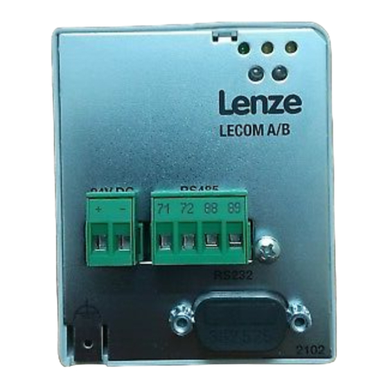
  • Seite 5 Pos. Beschreibung Ausführliche Information Kommunikationsmodul EMF2102IBC−V001, LECOM−A/B (RS232/RS485) Kommunikationsmodul EMF2102IBC−V002, LECOM−B (RS485) Kommunikationsmodul EMF2102IBC−V003, LECOM−LI (Lichtwellenleiter) Kommunikationsmodul EMF2102IBC−V004, LECOM−A (RS232) E82ZBL−C: Kommunikationsmodul EMF2102IBC−V004, LECOM−A (RS232), mit ^ 29 Handterminal Statusanzeige (grün) Spannungsversorgung Statusanzeige (gelb) Datenempfang ^ 43 Statusanzeige (gelb) Datenversand Statusanzeige (rot/grün) des Antriebsreglers ^ 24 Steckerleiste, Anschluss für externe Spannungsversorgung...
  • Seite 6 Inhalt Über diese Dokumentation ......... . Verwendete Konventionen .
  • Seite 7 ƒ Kommunikationsmodule EMF2102IBC−V00X / E82ZBL−C ab Version 3x.3x. Zielgruppe Diese Dokumentation richtet sich an Personen, die die Vernetzung und Fernwartung einer Maschine projektieren, installieren, in Betrieb nehmen und warten. Tipp! Informationen und Hilfsmittel rund um die Lenze−Produkte finden Sie im Download−Bereich unter www.lenze.com EDKMF2102 DE/EN/FR 8.0...
  • Seite 8 Über diese Dokumentation Verwendete Konventionen Verwendete Konventionen Diese Dokumentation verwendet folgende Konventionen zur Unterscheidung verschiede- ner Arten von Information: Informationsart Auszeichnung Beispiele/Hinweise Zahlenschreibweise Dezimaltrennzeichen Punkt Es wird generell der Dezimalpunkt verwendet. Beispiel: 1234.56 Symbole Seitenverweis Verweis auf eine andere Seite mit zu- sätzlichen Informationen Beispiel: 16 = siehe Seite 16...
  • Seite 9 Über diese Dokumentation Verwendete Hinweise Verwendete Hinweise Um auf Gefahren und wichtige Informationen hinzuweisen, werden in dieser Dokumenta- tion folgende Piktogramme und Signalwörter verwendet: Sicherheitshinweise Aufbau der Sicherheitshinweise: Gefahr! (kennzeichnet die Art und die Schwere der Gefahr) Hinweistext (beschreibt die Gefahr und gibt Hinweise, wie sie vermieden werden kann) Piktogramm und Signalwort Bedeutung Gefahr von Personenschäden durch gefährliche elektri-...
  • Seite 10 Über diese Dokumentation Verwendete Hinweise Anwendungshinweise Piktogramm und Signalwort Bedeutung Wichtiger Hinweis für die störungsfreie Funktion Hinweis! Nützlicher Tipp für die einfache Handhabung Tipp! Verweis auf andere Dokumentation EDKMF2102 DE/EN/FR 8.0...
  • Seite 11 Sicherheitshinweise Sicherheitshinweise Gefahr! Unsachgemäßer Umgang mit dem Kommunikationsmodul und dem Grundgerät kann schwere Personenschäden und Sachschäden verursachen. Beachten Sie die in der Dokumentation zum Grundgerät enthaltenen Sicherheitshinweise und Restgefahren. Stop! Elektrostatische Entladung Durch elektrostatische Entladung können elektronische Bauteile innerhalb des Kommunikationsmoduls beschädigt oder zerstört werden.
  • Seite 12 Das Kommunikationsmodul 2102−Vxxx / E82ZBL−C ermöglicht die Kommunikation von Lenze-Grundgeräten über Kabel (RS232/485−Interface) oder Lichtwellenleiter. Bestimmungsgemäße Verwendung Das Kommunikationsmodul EMF2102IBC−Vxxx / E82ZBL−C ... ƒ ist ein Betriebsmittel zum Einsatz in industriellen Starkstromanlagen; ƒ ist eine Zubehör−Baugruppe, die mit folgenden Lenze Grundgeräten eingesetzt werden kann: Gerätetyp V001 V002...
  • Seite 13 Produktbeschreibung Bestimmungsgemäße Verwendung Gerätetyp V001 V002 V003 V004 E82ZBL−C Drive PLC · · · · – EPL10200 E 1x.20 Servo−Umrichter 9300 · · · · · – 33.93XXxE.2x.1x · · · · · – 33.93XXxC.2x.1x Frequenzumrichter 9300 · · · ·...
  • Seite 14 (nicht im Lieferumfang enthalten) ƒ PC−Systemkabel EWL00xx ƒ Verbindungsleitung E82ZWLxxx ƒ Parametriersoftware "Global Drive Control (GDC)", ab Version 3.2 Tipp! Weiterführende Informationen zu diesem Kommunikationsmodul finden Sie im entsprechenden Kommunikationshandbuch. Die PDF−Datei finden Sie im Download−Bereich unter http://www.Lenze.com EDKMF2102 DE/EN/FR 8.0...
  • Seite 15 Produktbeschreibung Identifikation Identifikation Type Id.-No. Prod.-No. Ser.-No.  E82AF000P0B201XX 99371BC013  33.2102IBC V00x Gerätereihe LECOM Hardwarestand Softwarestand Variante 001: RS485/232−Schnittstelle 002: RS485−Schnittstelle 003: LWL−Schnittstelle 004: RS232−Schnittstelle EDKMF2102 DE/EN/FR 8.0...
  • Seite 16 Technische Daten Allgemeine Daten und Einsatzbedingungen Technische Daten Allgemeine Daten und Einsatzbedingungen Bereich Kommunikationsmodul EMF2102IBC −V001 −V002 −V003 −V004 / E82ZBL−C Kommunikations− RS232 RS485 RS232 (LECOM−A) (LECOM−B) (LECOM−LI) (LECOM−A) medien RS485 (LECOM−B) Strombedarf 80 mA 60 mA 70 mA − Protokoll LECOM−A/B V2.0 Übertragungszei-...
  • Seite 17 Technische Daten Schutzisolierung Schutzisolierung Schutzisolierung zwischen Art der Isolierung für Kommunikationsmodule EMF2102IBC Bus und ... −V001 −V002 −V003 −V004 / E82ZBL−C Bezugserde / PE Betriebsisolierung nicht Betriebsisolierung erforderlich externer Versorgung Betriebsisolierung verstärkte − Isolierung Leistungsteil 820X / 821X Basisisolierung verstärkte Basisisolierung Isolierung verstärkte Isolierung...
  • Seite 18 Technische Daten Abmessungen Abmessungen LECOM A/B/LI 24V DC RS485 71 72 88 89 RS232 2102 2102LEC013 61 mm 83 mm (nur EMF2102IBC−V003, LECOM−LI) 75 mm 28 mm 18 mm EDKMF2102 DE/EN/FR 8.0...
  • Seite 19 Mechanische Installation Mechanische Installation 2102LEC014 Abb. 1 Kommunikationsmodul aufstecken ƒ Stecken Sie das Kommunikationsmodul auf das Grundgerät (hier: 8200 vector). ƒ Schrauben Sie das Kommunikationsmodul mit der Befestigungsschraube auf dem Grundgerät fest, um eine gute PE−Verbindung sicher zu stellen. Hinweis! Zur internen Versorgung des Kommunikationsmoduls durch den Frequenzumrichter 8200 vector muss der Jumper in der Schnittstellenöffnung (siehe Abb.
  • Seite 20 Elektrische Installation Verdrahtung mit einem Leitrechner Elektrische Installation Verdrahtung mit einem Leitrechner Gefahr! Sie müssen eine zusätzliche Potenzialtrennung installieren, wenn ... ein Antriebsregler 820X und 821X mit einem Leitrechner verbunden wird ƒ eine sichere Potenzialtrennung (verstärkte Isolierung) nach EN 61800−5−1 ƒ...
  • Seite 21 Elektrische Installation Verdrahtung mit einem Leitrechner Spezifikation des Übertragungskabels Hinweis! Verwenden Sie ausschließlich Kabel, die den aufgeführten Spezifikationen entsprechen. Spezifikation Übertragungskabel für RS232 Kabeltyp LIYCY 4 x 0.25 mm , abgeschirmt Leitungswiderstand < 100 Kapazitätsbelag < 140 nF/km Spezifikation Übertragungskabel für RS485 Gesamtleitungslänge bis 300 m: Kabeltyp LIYCY 1 x 2 x 0.5 mm...
  • Seite 22 Elektrische Installation Verdrahtung mit einem Leitrechner Spezifikation Lichtwellenleiter−Kabel Minimaler Biegeradius 30 mm Maximale Zugkraft 100 N Spannungsfestigkeit 110 kV/m *40°C ... )80 C Arbeitstemperatur Wellenlänge 660 nm Dämpfung 100 dB/km ... 400 dB/km Leitungslänge zwischen zwei Teilneh- 0 bis 40 m (normale Sendeleistung) mern 10 bis 66 m (hohe Sendeleistung) (Kabeldämpfung = 150 dB/km)
  • Seite 23 Elektrische Installation EMV−gerechte Verdrahtung EMV−gerechte Verdrahtung Für eine EMV−gerechte Verdrahtung beachten Sie folgende Punkte: Hinweis! Steuer−/Datenleitungen getrennt von Motorleitungen verlegen. ƒ Legen Sie die Schirme der Steuer−/Datenleitungen bei digitalen Signalen ƒ beidseitig auf. Zur Vermeidung von Potenzialdifferenzen zwischen den ƒ Kommunikationsteilnehmern eine Ausgleichsleitung mit einem Querschnitt von mindestens 16 mm einsetzen (Bezug: PE).
  • Seite 24 Elektrische Installation Spannungsversorgung Spannungsversorgung Externe Spannungsversorgung Hinweis! Verwenden Sie bei externer Spannungsversorgung und bei größeren Entfernungen zwischen den Schaltschränken in jedem Schaltschrank immer ein separates und nach EN 61800−5−1 sicher getrenntes Netzteil (SELV/PELV). ƒ Die externe Spannungsversorgung des Kommunikationsmoduls ist notwendig, wenn beim Ausfall der Versorgung des Grundgerätes die Kommunikation bestehen bleiben soll.
  • Seite 25 Elektrische Installation Spannungsversorgung Interne Spannungsversorgung Hinweis! Die Vorgabe der internen Spannungsversorgung ist bei Grundgeräten mit erweiterter AIF−Schnittstellenöffnung (z. B. Frontseite 8200 vector) gegeben. Die in der Grafik grau hervorgehobene Fläche kennzeichnet die Jumper−Position. Im Auslieferungszustand des Grundgerätes werden diese nicht intern ƒ...
  • Seite 26 Elektrische Installation Daten der Anschlussklemmen Daten der Anschlussklemmen Bereich Werte Elektrischer Anschluss Steckerleiste mit Schraubanschluss Anschlussmöglichkeiten starr: 1.5 mm (AWG 16) flexibel: ohne Aderendhülse 1.5 mm (AWG 16) mit Aderendhülse, ohne Kunststoffhülse 1.5 mm (AWG 16) mit Aderendhülse, mit Kunststoffhülse 1.5 mm (AWG 16) Anzugsmoment...
  • Seite 27 Elektrische Installation Verbindungsaufbau über RS232 (LECOM−A) Verbindungsaufbau über RS232 (LECOM−A) 2102LEC009 Hinweis! Verwenden Sie ein vorkonfektioniertes PC−Systemkabel (EWL00xx). EDKMF2102 DE/EN/FR 8.0...
  • Seite 28 Elektrische Installation Verbindungsaufbau über RS232 (LECOM−A) RS232 2102 2102LEC015 RS232−Schnittstelle für Kommunikationsmodul EMF2102IBC−V001 / −V004 (Sub−D− Buchse, 9−polig) Bezeichnung Ein−/Ausgang Belegung − − unbenutzt Eingang Datenempfangsleitung RS232 Ausgang Datensendeleitung RS232 Ausgang Sendesteuerung − Bezugspotential Eingang unbenutzt RS232 T/R(A) Ein−/Ausgang RS485 (nur 2102−V001) T/R(B) Ein−/Ausgang RS485 (nur 2102−V001)
  • Seite 29 Elektrische Installation EMF2102IBC−V004 mit Handterminal (LECOM−A) EMF2102IBC−V004 mit Handterminal (LECOM−A) E82ZWLxxx EWL00xx 8200 motec 2102LEC016 Hinweis! Verwenden Sie ein vorkonfektioniertes PC−Systemkabel (EWL00xx). EDKMF2102 DE/EN/FR 8.0...
  • Seite 30 Elektrische Installation EMF2102IBC−V004 mit Handterminal (LECOM−A) So verdrahten Sie die Komponenten: 1. Kommunikationsmodul über PC−Systemkabel  mit dem PC verbinden. 2. Verbindungsleitung ‚ in das Handterminal einstecken. 3. Verschlussstopfen ƒ am Kühlkörper entfernen. 4. Verbindungsleitung ‚ in die AIF−Schnittstelle des Antriebsreglers einstecken. 5.
  • Seite 31 Elektrische Installation Verbindungsaufbau über RS485 (LECOM−B) Verbindungsaufbau über RS485 (LECOM−B) 2102LEC010 Hinweis! Verwenden Sie bitte für die Verdrahtung des RS485−Schnittstellenkabels nur abgeschirmtes und paarig verseiltes Kabel ! EDKMF2102 DE/EN/FR 8.0...
  • Seite 32 Elektrische Installation Verbindungsaufbau über RS485 (LECOM−B) 2102LEC018 RS485−Schnittstelle über Steckerleiste, 4−polig Klemme Bezeichnung Belegung T/R(B) RS485 T/R(A) RS485 S−C Kapazitive Schirmung nach PE Direkte Schirmung nach PE EDKMF2102 DE/EN/FR 8.0...
  • Seite 33 Elektrische Installation Verbindungsaufbau über RS485 (LECOM−B) LECOM LECOM IPC/SPS 24V DC RS485 24V DC RS485 71 72 88 89 71 72 88 89 RS232 RS232 2102 2102 2102LEC011 Verbindung zwischen zwei Antriebsreglern ƒ Den Kabelschirm auf Klemme 89 (direkt PE) des einen Kommunikationsmoduls und auf Klemme 88 (kapazitiv PE) des anderen Kommunikationsmoduls legen.
  • Seite 34 Elektrische Installation Verbindungsaufbau über Lichtwellenleiter (LECOM−LI) Verbindungsaufbau über Lichtwellenleiter (LECOM−LI) 2102LEC012 Eigenschaften der Verdrahtung für Lichtwellenleiter Kommunikationsmedien Lichtwellenleiter (Kunststoff) Netzwerk−Topologie Ring Mögliche Anzahl der Antriebsregler Maximale Leitungslänge 0 bis 40 m bei normaler Sendeleistung (S1 = OFF) 10 bis 66 m bei hoher Sendeleistung (S1 = ON) EDKMF2102 DE/EN/FR 8.0...
  • Seite 35 Elektrische Installation Verbindungsaufbau über Lichtwellenleiter (LECOM−LI) Lichtwellenleiter−Kabel (LWL−Kabel) zur Verdrahtung vorbereiten LWL−Kabel konfektionieren Die LWL−Kabel können ohne Spezialwerkzeug konfektioniert werden. 1. LWL−Kabel auf eine harte Unterlage legen und z. B. mit einem Messer auf die gewünschte Länge zuschneiden. 2. Bei LWL−Kabeln mit PUR−Mantel (rot) ca. 20 mm abisolieren (das Abisolieren von PE−Material ist nicht erforderlich).
  • Seite 36 Inbetriebnahme Vor dem ersten Einschalten Inbetriebnahme Vor dem ersten Einschalten Stop! Bevor Sie das Grundgerät mit dem Kommunikationsmodul erstmalig einschalten, überprüfen Sie ... die gesamte Verdrahtung auf Vollständigkeit, Kurzschluss und Erdschluss; ƒ bei Verwendung des Kommunikationsmoduls EMF2102IBC−V003 ƒ (LECOM−LI) die Stellung des Umschalters für die erforderliche Sendeleistung (^ 34).
  • Seite 37 Der Wert kann z. B. über das Keypad XT vorgegeben werden. Änderungen dieser Codestelle werden sofort wirksam. Lenze−Einstellung: 9600 kBit/s Geräteadresse zuweisen. Jedem Busteilnehmer mit Codestelle C0009 eine im Netzwerk eindeutige Geräteadresse zuweisen. Nur so kann der Leitrechner einen bestimmten Antriebsregler auch eindeutig erreichen.
  • Seite 38 Inbetriebnahme Inbetriebnahme mit Grundgeräten der Reihe 8200 Schritt Vorgehensweise Ausführliche Information Nun können Sie mit jedem Antriebsregler kommunizieren, d. h. Sie können alle Codestellen lesen und alle beschreibbaren Codestellen verändern. Weitere erforderliche Einstellungen am Antriebsregler vornehmen. Dokumentation Antriebsregler W Inbetriebnahme des Antriebsreglers Den Frequenz−Sollwert mit C0046 und das Steuerwort mit C0135 vorgeben.
  • Seite 39 Der Wert kann z. B. über das Keypad XT vorgegeben werden. Änderungen dieser Codestelle werden sofort wirksam. Lenze−Einstellung: 9600 kBit/s Geräteadresse zuweisen. Jedem Busteilnehmer mit Codestelle C0009 eine im Netzwerk eindeutige Geräteadresse zuweisen. Nur so kann der Leitrechner einen bestimmten Antriebsregler auch eindeutig erreichen.
  • Seite 40 Inbetriebnahme Inbetriebnahme mit Grundgeräten der Reihe 9300 Schritt Vorgehensweise Ausführliche Information Dokumentation Weitere erforderliche Einstellungen am Antriebsregler vornehmen. Antriebsregler W Inbetriebnahme des Antriebsreglers Für die Erst−Inbetriebnahme die Codestelle C0005 = 1011 einstel- len (Signalkonfiguration: Drehzahlregelung über AIF). Antriebsregler freigeben. – Die Klemme 28 (RFR: Reglerfreigabe) ist immer aktiv und muss während des Betriebs auf HIGH−Pegel liegen.
  • Seite 41 Der Wert kann z. B. über das Keypad XT vorgegeben werden. Änderungen dieser Codestelle werden sofort wirksam. Lenze−Einstellung: 9600 kBit/s Geräteadresse zuweisen. Jedem Busteilnehmer mit Codestelle C0009 eine im Netzwerk eindeutige Geräteadresse zuweisen. Nur so kann der Leitrechner einen bestimmten Antriebsregler auch eindeutig erreichen.
  • Seite 42 Inbetriebnahme Inbetriebnahme mit Grundgeräten der Reihe ECS Schritt Vorgehensweise Ausführliche Information Dokumentation Weitere erforderliche Einstellungen am Antriebsregler vornehmen. Antriebsregler W Inbetriebnahme des Antriebsreglers Für die Erst−Inbetriebnahme die Codestelle C0005 = 1003 einstel- len (Signalkonfiguration: Drehzahlregelung über AIF). Antriebsregler freigeben. – Die Klemmen SI1 ( Reglerfreigabe) und SI2 (Impulssperre) sind immer aktiv und müssen während des Betriebs auf HIGH−...
  • Seite 43 Diagnose LED−Statusanzeigen Diagnose LED−Statusanzeigen Pos. Farbe Zustand Beschreibung grün Das Kommunikationsmodul ist mit Spannung versorgt und hat eine Verbindung zum Antriebsregler. Das Kommunikationsmodul ist nicht mit Spannung versorgt. Der An- triebsregler oder die externe Spannungsversorgung ist ausgeschaltet. blinkt Das Kommunikationsmodul ist mit Spannung versorgt, hat aber (noch) keine Verbindung zum Antriebsregler, weil ...
  • Seite 44 2102LEC001b 2102LEC002b 2102LEC003b 2102LEC004b 2102LEC007 E82ZBLC001C 0Fig. 0Tab. 0 EDKMF2102 DE/EN/FR 8.0...
  • Seite 45 Pos. Description Detailed information Communication module EMF2102IBC−V001, LECOM−A/B (RS232/RS485) Communication module EMF2102IBC−V002, LECOM−B (RS485) Communication module EMF2102IBC−V003, LECOM−LI (optical fibre) Communication module EMF2102IBC−V004, LECOM−A (RS232) E82ZBL−C: communication module EMF2102IBC−V004, LECOM−A (RS232), ^ 68 with diagnosis terminal Status indicator (green) voltage supply Status indicator (yellow) data reception ^ 82 Status indicator (yellow) data transmission...
  • Seite 46 Contents About this documentation ......... . . Conventions used .
  • Seite 47 Contents This documentation provides ... ƒ safety instructions that must be observed; ƒ information about the versions of the Lenze standard devices to be used; ƒ information about the mechanical and electrical installation of the communication module; ƒ information about commissioning and diagnosing.
  • Seite 48 About this documentation Conventions used Conventions used This documentation uses the following conventions to distinguish between different types of information: Type of information Identification Examples/notes Numbers Decimal separator Point The decimal point is used throughout this documentation. Example: 1234.56 Symbols Page reference Reference to another page with additional information...
  • Seite 49 About this documentation Notes used Notes used The following pictographs and signal words are used in this documentation to indicate dangers and important information: Safety instructions Structure of safety instructions: Danger! (characterises the type and severity of danger) Note (describes the danger and gives information about how to prevent dangerous situations) Pictograph and signal word Meaning...
  • Seite 50 About this documentation Notes used Application notes Pictograph and signal word Meaning Important note to ensure troublefree operation Note! Useful tip for simple handling Tip! Reference to another documentation EDKMF2102 DE/EN/FR 8.0...
  • Seite 51 Safety instructions Safety instructions Danger! Inappropriate handling of the communication module and the standard device can cause serious personal injury and material damage. Observe the safety instructions and residual hazards described in the documentation for the standard device. Stop! Electrostatic discharge Electronic components of the communication module can be damaged or destroyed through electrostatic discharge.
  • Seite 52 (RS232/485 interface) or optical fibre. Application as directed The communication module EMF2102IBC−Vxxx / E82ZBL−C ... ƒ is a device intended for use in industrial power systems; ƒ is an accessory module for use in conjunction with the following Lenze standard devices: Device type V001...
  • Seite 53 Product description Application as directed Device type V001 V002 V003 V004 E82ZBL−C Drive PLC · · · · – EPL10200 E 1x.20 9300 servo inverter · · · · · – 33.93XXxE.2x.1x · · · · · – 33.93XXxC.2x.1x 9300 frequency inverter ·...
  • Seite 54 ƒ Parameterisation software "Global Drive Control (GDC)", version 3.2 or higher Tip! Further information regarding this communication module can be found in the corresponding communication manual. The PDF file can be found in the download area at http://www.Lenze.com EDKMF2102 DE/EN/FR 8.0...
  • Seite 55 Product description Identification Identification Type Id.-No. Prod.-No. Ser.-No.  E82AF000P0B201XX 99371BC013  33.2102IBC V00x LECOM device series Hardware version Software version Variant 001: RS485/232 interface 002: RS485 interface 003: Optical fibre interface 004: RS232 interface EDKMF2102 DE/EN/FR 8.0...
  • Seite 56 Technical data General data and operating conditions Technical data General data and operating conditions Area Communication module EMF2102IBC −V001 −V002 −V003 −V004 / E82ZBL−C Communication RS232 RS485 Optical fibre RS232 (LECOM−A) (LECOM−B) (LECOM−A) media RS485 (LECOM−LI) (LECOM−B) Current consumption 80 mA 60 mA 70 mA −...
  • Seite 57 Technical data Protective insulation Protective insulation Protective insulation between Type of insulation for communication module EMF2102IBC bus and ... −V001 −V002 −V003 −V004 / E82ZBL−C Reference earth / PE Functional insulation Not required Functional insulation External supply Functional insulation Reinforced −...
  • Seite 58 Technical data Dimensions Dimensions LECOM A/B/LI 24V DC RS485 71 72 88 89 RS232 2102 2102LEC013 61 mm 83 mm (only EMF2102IBC−V003, LECOM−LI) 75 mm 28 mm 18 mm EDKMF2102 DE/EN/FR 8.0...
  • Seite 59 Mechanical installation Mechanical installation 2102LEC014 Fig. 1 Attaching the communication module ƒ Plug the communication module onto the standard device (here: 8200 vector). ƒ Tighten the communication module to the standard device using the fixing screw in order to ensure a good PE connection. Note! For the internal supply of the communication module by the 8200 vector frequency inverter the jumper has to be adjusted within the interface opening...
  • Seite 60 Electrical installation Wiring to a host Electrical installation Wiring to a host Danger! You have to provide additional electrical isolation if ... an 820X and 821X controller is connected to the host and ƒ a safe electrical isolation (reinforced insulation) according to EN 61800−5−1 ƒ...
  • Seite 61 Electrical installation Wiring to a host Specification of the transmission cable Note! Only use cables complying with the below specifications. Specification of transmission cable for RS232 Cable type LIYCY 4 x 0.25 mm , shielded Cable resistance < 100 Capacitance per unit length <...
  • Seite 62 Electrical installation EMC−compliant wiring EMC−compliant wiring For wiring according to EMC requirements observe the following points: Note! Separate control/data cables from motor cables. ƒ In case of digital signals, connect the shields of control/data cables on both ƒ sides. Use an equalizing conductor with a cross−section of at least 16 mm ƒ...
  • Seite 63 Electrical installation Voltage supply Voltage supply External voltage supply Note! In the case of an external voltage supply and for greater distances between the control cabinets, always use a separate power supply unit (SELV/PELV) that is safely separated in accordance with EN 61800−5−1 in each control cabinet. ƒ...
  • Seite 64 For internal voltage supply place the jumper on the position indicated ƒ below. In the case of all other device series (9300, ECS), voltage is always supplied from the standard device. Lenze setting Internal voltage supply (Only external voltage supply possible.) EDKMF2102 DE/EN/FR 8.0...
  • Seite 65 Electrical installation Connection terminals Connection terminals Area Values Electrical connection Plug connector with screw connection Possible connections rigid: 1.5 mm (AWG 16) flexible: without wire end ferrule 1.5 mm (AWG 16) with wire end ferrule, without plastic sleeve 1.5 mm (AWG 16) with wire end ferrule, with plastic sleeve 1.5 mm...
  • Seite 66 Electrical installation Connection established via RS232 (LECOM−A) Connection established via RS232 (LECOM−A) 2102LEC009 Note! Use a prefabricated PC system cable (EWL00xx). EDKMF2102 DE/EN/FR 8.0...
  • Seite 67 Electrical installation Connection established via RS232 (LECOM−A) RS232 2102 2102LEC015 RS232 interface for communication module EMF2102IBC−V001 / −V004 (Sub−D socket, 9−pole) Designation Input/output Assignment − − unused Input RS232 data receive line Output RS232 data transmit line Output Transmit control −...
  • Seite 68 Electrical installation EMF2102IBC−V004 with diagnosis terminal (LECOM−A) EMF2102IBC−V004 with diagnosis terminal (LECOM−A) E82ZWLxxx EWL00xx 8200 motec 2102LEC016 Note! Use a prefabricated PC system cable (EWL00xx). EDKMF2102 DE/EN/FR 8.0...
  • Seite 69 Electrical installation EMF2102IBC−V004 with diagnosis terminal (LECOM−A) How to wire the components: 1. Connect communication module to PC via PC system cable . 2. Insert connecting cable ‚ into diagnosis terminal. 3. Remove plug ƒ from heatsink. 4. Insert connecting cable ‚ into the AIF interface of the controller. 5.
  • Seite 70 Electrical installation Connection established via RS485 (LECOM−B) Connection established via RS485 (LECOM−B) 2102LEC010 Note! Please always use shielded and twisted pair cables when wiring the RS485 interface cable! EDKMF2102 DE/EN/FR 8.0...
  • Seite 71 Electrical installation Connection established via RS485 (LECOM−B) 2102LEC018 RS485 interface via plug connector, 4−pole Terminal Designation Assignment T/R(B) RS485 T/R(A) RS485 S−C Capacitive shielding to PE Direct shielding to PE EDKMF2102 DE/EN/FR 8.0...
  • Seite 72 Electrical installation Connection established via RS485 (LECOM−B) LECOM LECOM IPC/SPS 24V DC RS485 24V DC RS485 71 72 88 89 71 72 88 89 RS232 RS232 2102 2102 2102LEC011 Connection between two drive controllers ƒ Connect cable shield to terminal 89 (direct PE) of the first communication module and terminal 88 (capacitive PE) of the other communication module.
  • Seite 73 Electrical installation Connection established via optical fibre (LECOM−LI) Connection established via optical fibre (LECOM−LI) 2102LEC012 Features of wiring for optical fibre Communication media Optical fibre (plastic) Network topology Ring Possible number of drive controllers Maximum cable length 0 to 40 m at normal output power (S1 = OFF) 10 to 66 m at high output power (S1 = ON) EDKMF2102 DE/EN/FR 8.0...
  • Seite 74 Electrical installation Connection established via optical fibre (LECOM−LI) Preparing the optical fibre cable for wiring Trimming the optical fibre cable Optical fibre cables can be trimmed without the need for special tools. 1. Place optical fibre cable on a hard surface and cut to required length using a knife, for example.
  • Seite 75 Commissioning Before switching on Commissioning Before switching on Stop! Before switching on the standard device with the communication module for the first time, ... check the entire wiring with regard to completeness, short circuit, and ƒ earth fault; when using the communication module EMF2102IBC−V003 (LECOM−LI), ƒ...
  • Seite 76 The baud rate setting must be identical for all bus nodes. The value can be selected e.g. via the Keypad XT. Changes in this code are effective immediately. Lenze setting: 9600 kBits/sec. Assign the device address Use code C0009 to assign a unique device address to every node of the network.
  • Seite 77 Commissioning Commissioning for 8200 series standard devices Step Procedure Detailed information It is now possible to communicate with any controller, i. e. all codes can be read and all writable codes can be changed. Make other necessary controller settings. Documentation for the respective W Commissioning of the controller controller...
  • Seite 78 The baud rate setting must be identical for all bus nodes. The value can be selected e.g. via the Keypad XT. Changes in this code are effective immediately. Lenze setting: 9600 kBits/sec. Assign the device address Use code C0009 to assign a unique device address to every node of the network.
  • Seite 79 Commissioning Commissioning for 9300 series standard devices Step Procedure Detailed information Documentation Make other necessary controller settings. for the respective W Commissioning of the controller controller For initial commissioning set code C0005 = 1011 (signal configuration: speed control via AIF). Enable the controller.
  • Seite 80 The baud rate setting must be identical for all bus nodes. The value can be selected e.g. via the Keypad XT. Changes in this code are effective immediately. Lenze setting: 9600 kBits/sec. Assign the device address Use code C0009 to assign a unique device address to every node of the network.
  • Seite 81 Commissioning Commissioning for ECS series standard devices Step Procedure Detailed information Documentation Make other necessary controller settings. for the respective W Commissioning of the controller controller For initial commissioning set code C0005 = 1003 (signal configuration: speed control via AIF). Enable the controller.
  • Seite 82 Diagnostics LED status displays Diagnostics LED status displays Pos. Colour Status Description Green The communication module is supplied with voltage and has a connection to the drive controller. The communication module is not supplied with voltage. The controller or the external voltage supply is switched off. Blinking The communication module is supplied with voltage, but is not (yet) connected to the controller because ...
  • Seite 83 Diagnostics LED status displays EDKMF2102 DE/EN/FR 8.0...
  • Seite 84 2102LEC001b 2102LEC002b 2102LEC003b 2102LEC004b 2102LEC007 E82ZBLC001C 0Fig. 0Tab. 0 EDKMF2102 DE/EN/FR 8.0...
  • Seite 85 Pos. Description Informations détaillées Module de communication EMF2102IBC−V001, LECOM−A/B (RS232/RS485) Module de communication −V002, LECOM−B (RS485) Module de communication EMF2102IBC−V003, LECOM−LI (fibre optique) Module de communication EMF2102IBC−V004, LECOM−A (RS232) E82ZBL−C : module de communication EMF2102IBC−V004, LECOM−A (RS232) ^ 108 muni d’un clavier de commande avec support Affichage d’état (vert) : alimentation Affichage d’état (jaune) : réception de données ^ 122...
  • Seite 86 Sommaire Présentation du document ......... . . Conventions utilisées .
  • Seite 87 Contenu La présente documentation contient ... ƒ des consignes de sécurité à respecter impérativement ; ƒ des renseignements sur les versions d’appareils de base Lenze à utiliser ; ƒ des informations sur l’installation mécanique et électrique du module de communication ƒ...
  • Seite 88 Présentation du document Conventions utilisées Conventions utilisées Pour distinguer les différents types d’information, cette documentation utilise les conventions suivantes : Type d’information Aperçu Exemples/remarques Représentation des chiffres Séparateur décimal Point Le point décimal est généralement utilisé. Exemple : 1234.56 Pictogrammes Renvoi à...
  • Seite 89 Présentation du document Consignes utilisées Consignes utilisées Pour indiquer des risques et des informations importantes, la présente documentation utilise les mots et pictogrammes suivants : Consignes de sécurité Présentation des consignes de sécurité Danger ! (Le pictogramme indique le type de risque.) Explication (L’explication décrit le risque et les moyens de l’éviter.) Pictogramme et mot associé...
  • Seite 90 Présentation du document Consignes utilisées Consignes d’utilisation Pictogramme et mot associé Explication Remarque Remarque importante pour assurer un fonctionnement correct importante ! Conseil utile pour faciliter la mise en œuvre Conseil ! Renvoi à une autre documentation EDKMF2102 DE/EN/FR 8.0...
  • Seite 91 Consignes de sécurité Consignes de sécurité Danger ! Toute utilisation non conforme à la fonction du module de communication et de l’appareil de base risque d’entraîner des blessures graves et des dommages matériels. Tenir compte des consignes de sécurité et des dangers résiduels indiqués dans la documentation de l’appareil de base.
  • Seite 92 Le module de communication EMF2102IBC−Vxxx / E82ZBL−C ... ƒ est un matériel d’exploitation destiné à être utilisé dans les installations industrielles à courant fort ; ƒ est un accessoire compatible avec les appareils de base Lenze suivants : Type d’appareil V001...
  • Seite 93 Description du produit Utilisation conforme à la fonction Type d’appareil V001 V002 V003 V004 E82ZBL−C Drive PLC · · · · – EPL10200 E 1x.20 Servovariateur 9300 · · · · · – 33.93XXxE.2x.1x · · · · · – 33.93XXxC.2x.1x Convertisseur de fréquence 9300 ·...
  • Seite 94 ƒ Logiciel de paramétrage "Global Drive Control (GDC)", à partir de la version 3.2 Conseil ! Pour plus d’informations sur le module de communication, consulter le manuel de communication correspondant. Le fichier au format PDF peut être téléchargé à l’adresse suivante : http://www.Lenze.com EDKMF2102 DE/EN/FR 8.0...
  • Seite 95 Description du produit Identification Identification Type Id.-No. Prod.-No. Ser.-No.  E82AF000P0B201XX 99371BC013  33.2102IBC V00x Série d’appareils LECOM Version matérielle Version logicielle Variante 001 : interface RS485/232 002 : interface RS485 003 : interface fibre optique 004 : interface RS232 EDKMF2102 DE/EN/FR 8.0...
  • Seite 96 Spécifications techniques Caractéristiques générales et conditions d’utilisation Spécifications techniques Caractéristiques générales et conditions d’utilisation Plage Module de communication EMF2102IBC −V001 −V002 −V003 −V004 / E82ZBL−C Support de RS232 RS485 Fibre optique RS232 (LECOM−A) (LECOM−B) (LECOM−A) communication RS485 (LECOM−LI) (LECOM−B) Consommation de 80 mA 60 mA 70 mA...
  • Seite 97 Spécifications techniques Isolement de protection Isolement de protection Isolement de protection entre Type d’isolement pour les modules de communication EMF2102IBC bus et... −V001 −V002 −V003 −V004 / E82ZBL−C point de terre / PE Isolement fonctionnel Isolement obligatoire fonctionnel alimentation externe Isolement fonctionnel Isolement −...
  • Seite 98 Spécifications techniques Encombrements Encombrements LECOM A/B/LI 24V DC RS485 71 72 88 89 RS232 2102 2102LEC013 61 mm 83 mm (uniquement EMF2102IBC−V003, LECOM−LI) 75 mm 28 mm 18 mm EDKMF2102 DE/EN/FR 8.0...
  • Seite 99 Installation mécanique Installation mécanique 2102LEC014 Fig. 1 Brancher le module de communication ƒ Enficher le module de communication dans l’appareil de base (ici : 8200 vector). ƒ Visser le module de communication sur l’appareil de base à l’aide de la vis de fixation pour assurer une bonne liaison avec la terre.
  • Seite 100 Installation électrique Raccordement à un maître Installation électrique Raccordement à un maître Danger ! Prévoir une séparation du potentiel supplémentaire dans les cas suivants : Un variateur de vitesse 820X et 821X est raccordé à un système maître et ƒ une séparation sûre du potentiel (isolement renforcé) selon EN 61800−5−1 ƒ...
  • Seite 101 Installation électrique Raccordement à un maître Spécifications pour le câble de transmission Remarque importante ! Utiliser exclusivement des câbles conformes aux spécifications indiquées. Spécifications du câble de transmission pour RS232 Type de câble LIYCY 4 x 0,25 mm , blindé Résistivité...
  • Seite 102 Installation électrique Câblage conforme CEM Câblage conforme CEM Pour s’assurer que le câblage est conforme aux exigences à respecter en matière de CEM, vérifier les points suivants : Remarque importante ! Séparer physiquement les câbles de commande/lignes de données des ƒ...
  • Seite 103 Installation électrique Alimentation Alimentation Alimentation externe Remarque importante ! En cas d’alimentation externe et d’écarts importants entre les armoires électriques, toujours utiliser un bloc d’alimentation avec coupure de sécurité ("SELV"/"PELV") distinct et conforme à la norme EN 61800−5−1 pour chaque armoire électrique.
  • Seite 104 Installation électrique Alimentation Alimentation interne Remarque importante ! Les appareils de base dotés d’une interface AIF étendue (face avant du 8200 vector par exemple) offrent la possibilité d’une alimentation interne. Sur l’illustration, la partie grisée désigne la position du cavalier. L’état à...
  • Seite 105 Installation électrique Spécifications des bornes de raccordement Spécifications des bornes de raccordement Domaine Spécifications Raccordement électrique Bornier à vis Possibilités de raccordement Fixe : 1.5 mm (AWG 16) Souple : sans embout 1.5 mm (AWG 16) avec embout, sans cosse en plastique 1.5 mm (AWG 16) avec embout et cosse en plastique...
  • Seite 106 Installation électrique Liaison via RS232 (LECOM−A) Liaison via RS232 (LECOM−A) 2102LEC009 Remarque importante ! Utiliser un câble système pour PC préfabriqué (EWL00xx). EDKMF2102 DE/EN/FR 8.0...
  • Seite 107 Installation électrique Liaison via RS232 (LECOM−A) RS232 2102 2102LEC015 Interface RS232 pour module de communication EMF2102IBC−V001 / −V004 (connecteur Sub−D femelle, 9 broches) Broche Désignation Entrée/sortie Affectation − − Non utilisé Entrée Ligne de réception de données RS232 Sortie Ligne d’envoi de données RS232 Sortie Commande de l’envoi −...
  • Seite 108 Installation électrique EMF2102IBC−V004 avec clavier de commande et support (LECOM−A) EMF2102IBC−V004 avec clavier de commande et support (LECOM−A) E82ZWLxxx EWL00xx 8200 motec 2102LEC016 Remarque importante ! Utiliser un câble système pour PC préfabriqué (EWL00xx). EDKMF2102 DE/EN/FR 8.0...
  • Seite 109 Installation électrique EMF2102IBC−V004 avec clavier de commande et support (LECOM−A) Pour procéder au câblage des composants : 1. Relier le module de communication au PC via le câble système pour PC . 2. Enficher le câble de liaison ‚ dans le boîtier déporté. 3.
  • Seite 110 Installation électrique Liaison via RS485 (LECOM−B) Liaison via RS485 (LECOM−B) 2102LEC010 Remarque importante ! Pour le raccordement via l’interface RS485, utiliser uniquement un câble torsadé par paire et blindé ! EDKMF2102 DE/EN/FR 8.0...
  • Seite 111 Installation électrique Liaison via RS485 (LECOM−B) 2102LEC018 Interface RS485 via bornier, 4 bornes Borne Désignation Affectation T/R(B) RS485 T/R(A) RS485 S−C Blindage capacitif vers PE Blindage direct vers PE EDKMF2102 DE/EN/FR 8.0...
  • Seite 112 Installation électrique Liaison via RS485 (LECOM−B) LECOM LECOM IPC/SPS 24V DC RS485 24V DC RS485 71 72 88 89 71 72 88 89 RS232 RS232 2102 2102 2102LEC011 Liaison entre deux variateurs de vitesse ƒ Appliquer le blindage du câble à la borne 89 (PE direct) du premier module de communication et à...
  • Seite 113 Installation électrique Liaison via fibre optique (LECOM−LI) Liaison via fibre optique (LECOM−LI) 2102LEC012 Caractéristiques de la liaison fibre optique Supports de communication Fibre optique (matière plastique) Topologie du réseau Anneau Nombre maximum de variateurs Longueur maximum du câble 0 ... 40 m pour un débit normal (S1 = OFF) 10 ...
  • Seite 114 Installation électrique Liaison via fibre optique (LECOM−LI) Préparation du câble à fibre optique pour le raccordement Confection du câble à fibre optique Les câbles fibre optique peuvent être confectionnés sans outil spécifique. 1. Poser le câble à fibre optique sur un support solide et le couper à la longueur souhaitée, par exemple à...
  • Seite 115 Mise en service Avant la première mise sous tension Mise en service Avant la première mise sous tension Stop ! Avant la première mise sous tension de l’appareil de base avec le module de communication, vérifier : le câblage dans son intégralité afin d’éviter un court−circuit ou un défaut ƒ...
  • Seite 116 Cette valeur peut être définie via le clavier de commande XT. Toute modification de ce code est appliquée sans délai. Réglage Lenze : 9 600 kbits/s Affecter une adresse d’appareil Attribuer à chaque participant au bus une adresse d’appareil univoque via le code C0009.
  • Seite 117 Mise en service Mise en service avec les appareils de base de la série 8200 Etape Procédure Informations détaillées Il est désormais possible de communiquer avec le variateur, c’est−à−dire de consulter tous les codes et modifier tous les codes programmables. Procéder aux autres réglages nécessaires sur le variateur de vitesse.
  • Seite 118 Cette valeur peut être définie via le clavier de commande XT. Toute modification de ce code est appliquée sans délai. Réglage Lenze : 9 600 kbits/s Affecter une adresse d’appareil à chaque participant au bus. Attribuer à chaque participant au bus une adresse d’appareil univoque via le code C0009.
  • Seite 119 Mise en service Mise en service avec les appareils de base de la série 9300 Etape Procédure Informations détaillées Documentation Procéder aux autres réglages nécessaires sur le variateur de vitesse. relative au W Mise en service du variateur de vitesse variateur de vitesse Lors de la première mise en service, régler le code C0005 sur 1011...
  • Seite 120 Cette valeur peut être définie via le clavier de commande XT. Toute modification de ce code est appliquée sans délai. Réglage Lenze : 9 600 kbits/s Affecter une adresse d’appareil Attribuer à chaque participant au bus une adresse d’appareil univoque via le code C0009.
  • Seite 121 Mise en service Mise en service avec les appareils de base de la série ECS Etape Procédure Informations détaillées Documentation Procéder aux autres réglages nécessaires sur le variateur de vitesse. relative au W Mise en service du variateur de vitesse variateur de vitesse Lors de la première mise en service, régler le code C0005 sur 1003...
  • Seite 122 Diagnostic Affichages d’état par LED Diagnostic Affichages d’état par LED Pos. Couleur Etat Description Vert Le module de communication est sous tension. La liaison avec le variateur de vitesse est établie. Le module de communication n’est pas sous tension. Le variateur est déconnecté...
  • Seite 123 Diagnostic Affichages d’état par LED EDKMF2102 DE/EN/FR 8.0...
  • Seite 124 ã K Q © 06/2015 Lenze Automation GmbH Service Lenze Service GmbH Postfach 10 13 52, 31763 Hameln Breslauer Straße 3, D−32699 Extertal Hans−Lenze−Str. 1, 31855 Aerzen GERMANY Germany HR Hannover B 205381 +49 5154 82−0 008000 2446877 (24 h helpline) Ê...