Inhaltsverzeichnis
Werbung
Quicklinks
Werbung
Inhaltsverzeichnis

Verwandte Anleitungen für Abit IC7-G


Inhaltszusammenfassung für Abit IC7-G
- Seite 1 IC7-G Socket 478 System Board User’s Manual 4200-0351-02 Rev. 1.00...
- Seite 2 No part of this manual may be reproduced, transmitted or transcribed without the expressed written permission of the manufacturer and authors of this manual. If you do not properly set the motherboard settings, causing the motherboard to malfunction or fail, we cannot guarantee any responsibility. IC7-G...
-
Seite 3: Inhaltsverzeichnis
Table Of Contents IC7-G 快速安裝指引 ................1 IC7-G のクイックインストールガイド ..........3 IC7-G Schnellinstallationsanleitung ............5 IC7-G Guide d’Installation Rapide ............7 Краткое руководство по установке IC7-G ......... 9 Guida all’installazione veloce Scheda madre IC7-G......11 Chapter 1. Introduction ................1-1 1-1. - Seite 4 Appendix F. BIOS Update Guide ................. F-1 Appendix G. Hardware Monitoring (The Winbond Hardware Doctor Utility) ..G-1 Appendix H. Installation Guide for Suspend to RAM .........H-1 Appendix I. Troubleshooting (Need Assistance?)..........I-1 Appendix J. How to Get Technical Support ............J-1 IC7-G...
-
Seite 5: Ic7-G 快速安裝指引
IC7-G 快速安裝指引 IC7-G 快速安裝指引 處理器的安裝 (Zero Insertion Force, ZIF) ® ® Socket 478 Intel Pentium 4 CPU ® Pentium 4 Socket 478 Socket 478 ® 注意: Pentium 注意: User’s Manual... - Seite 6 IC7-G 快速安裝指引 將主機板安裝到機殼上 安裝系統記憶體 DDR DIMM DDR DIMM DIMM DIMM 種 保 DDR DIMM 僅 DIMM DDR DIMM DIMM 退 DDR DIMM 自 地 依 DIMM1~DIMM4 順序 必需 必需 纜 連接 關 連接頭 連接 成 硬 作 連接器、連接頭以及附加卡的安裝 任 部...
-
Seite 7: Ic7-G のクイックインストールガイド
IC7-G のクイックインストールガイド IC7-G のクイックインストールガイド 完全なユーザ ーズマニュアルはこのマザーボードに付属するドライバとユーティリティ CD を検索して入手できます。 プロセッサの取り付け ZIF ( ® ® ) Socket 478 Intel Pentium ® Pentium Socket 478 1. Socket 478 ® 注意 : Pentium 2. CPU User’s Manual... - Seite 8 IC7-G のクイックインストールガイド 注意:プロセッサに対して、正しいバス周波数とマルチプルに設定することを忘れないでください。 マザーボードをシャーシに取り付ける システムメモリの取り付け DDR DIMM DDR DIMM DDR DIMM DDR DIMM DDR DIMM DDR DIMM DIMM1 DIMM4 コネクタ、ヘッダ、スイッチおよびアダプタ SCSI 電源コネクタを ATX 電源コネクタに差し込む BIOS のセットアップ ハードウェアの取り付けが 了したら、コンピュータの 源をオンにし、BIOS Setup アイテム に移 して、プロセッサのパラメータをセットアップします については、ユーザーズマニ ュアルの を参照してください IC7-G...
-
Seite 9: Ic7-G Schnellinstallationsanleitung
IC7-G Schnellinstallationsanleitung IC7-G Schnellinstallationsanleitung Beziehen Sie sich bitte für detaillierte Informationen über diese Hauptplatine auf die vollständige Version des Benutzerbuchs. Diese Schnellinstallationsanleitung ist für erfahrene Systemaufbauer gedacht. Ist es Ihr erster Versuch ein Computersystem aufzubauen, dann empfehlen wir Ihnen zuerst das vollständige Benutzerhandbuch zu lesen oder einen Techniker zum Aufbauen des Systems zu Hilfe zu holen. - Seite 10 IC7-G Schnellinstallationsanleitung 6. Kühlblechabdeckung und –basis sollten nun fest miteinander das Kühlblech umschließen. Achtung: Vergessen Sie nicht, die korrekte Busfrequenz und Multiplikator für Ihren Prozessor einzustellen. Installieren der Hauptplatine im Gehäuse Nach der Installation des Prozessors können Sie anfangen die Hauptplatine im Computergehäuse zu befestigen.
-
Seite 11: Ic7-G Guide D'installation Rapide
IC7-G Guide d’Installation Rapide IC7-G Guide d’Installation Rapide Pour des informations relatives à cette carte mère plus détaillées, veuillez vous référer à notre version complète du manuel utilisateur. Ce guide d’installation rapide est créé pour les assembleurs système expérimentés. S’il s’agit de votre premier essai pour installer un ordinateur, nous vous suggérons de lire d’abord le manuel en version complète ou de demander l’aide d’un technicien pour vous aider à... - Seite 12 IC7-G Guide d’Installation Rapide 6. Le couvercle support et la base du dissipateur thermique doivent maintenant être fermement fixés l'un à l'autre fermement avec le dissipateur thermique à l'intérieur. Attention: N'oubliez pas de régler une fréquence de Bus et un coefficient multiplicateur corrects pour votre processeur.
-
Seite 13: Краткое Руководство По Установке Ic7-G
Краткое руководство по установке IC7-G Краткое руководство по установке IC7-G Более подробные сведения о материнской плате приведены в руководстве пользователя. Краткое руководство по установке предназначено для опытных специалистов. Если вы собираете компьютер впервые, ознакомьтесь сперва с руководством пользователя или попросите техника... - Seite 14 Краткое руководство по установке IC7-G 6. Крышка и основание должны быть надежно скреплены, фиксируя радиатор. Внимание: Не забудьте установить для процессора надлежащую частоту шины и множитель. Установка материнской платы в корпус После установки процессора на материнскую плату можно начинать установку материнской...
-
Seite 15: Guida All'installazione Veloce Scheda Madre Ic7-G
Guida all’installazione veloce Scheda madre IC7-G Guida all’installazione veloce Scheda madre IC7-G Per maggiori e dettagliate informazioni su questa scheda madre si prega di fare riferimento alla versione integrale del Manuale utente. Questa guida all’installazione veloce è intesa per costruttori esperi di sistemi. - Seite 16 Guida all’installazione veloce Scheda madre IC7-G 6. Il coperchio di supporto e la base del dispersore di calore dovrebbero ora essere fissate saldamente l’uno all’altra, contenendo al loro interno il dispersore di calore. Attenzione: Non dimenticare di impostare la corretta frequenza BUS e multiplier per il processore.
-
Seite 17: Chapter 1. Introduction
Introduction Chapter 1. Introduction 1-1. Features & Specifications 1. CPU • Supports Intel Pentium 4 Socket 478 processor with 800/533/400MHz System Data Bus • Supports Intel Hyper-Threading Technology 2. Chipset • Intel 82875P (MCH) + 82801EB (ICH5R) • Supports dual channel DDR 400 with ECC function and “Performance Acceleration Technology (PAT)”... - Seite 18 The Serial ATA controller only supports Ultra DMA/ATA100 or higher hard drive. Do not use hard drives under this specification, or it won’t work. Specifications and information contained herein are subject to change without notice. IC7-G...
-
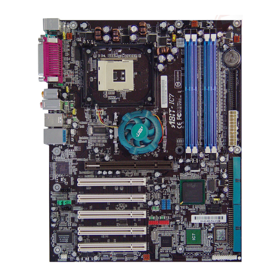
Seite 19: Layout Diagram
Introduction 1-2. Layout Diagram User’s Manual... - Seite 20 Chapter 1 Chapter 1 IC7-G IC7-G...
-
Seite 21: Chapter 2. Hardware Setup
Hardware Setup Chapter 2. Hardware Setup Before the Installation: Turn off the power supply switch (fully turn off the +5V standby power), or disconnect the power cord before installing or unplugging any connectors or add-on cards. Failing to do so may cause the motherboard components or add-on cards to malfunction or damaged. 2-1. - Seite 22 6. The heatsink supporting cover and base should now firmly locking up with each other with the heatsink inside. ATTENTION: Do not forget to set the correct bus frequency and multiple for your processor. IC7-G...
-
Seite 23: Install System Memory
Hardware Setup 2-3. Install System Memory This motherboard provides four 184-pin DDR DIMM slots for Single/Dual Channel DDR 400 memory modules with memory expansion size up to 4GB. To reach the performance of Dual Channel DDR, the following rules must be obeyed: •... - Seite 24 DIMM module. ATTENTION: Static electricity can damage the electronic components of the computer or optional boards. Before starting these procedures, ensure that you are discharged of static electricity by touching a grounded metal object briefly. IC7-G...
-
Seite 25: Connectors, Headers And Switches
Hardware Setup 2-4. Connectors, Headers and Switches Here we will show you all of the connectors, headers and switches, and how to connect them. Please read the entire section for necessary information before attempting to finish all the hardware installation inside the computer chassis. -
Seite 26: Fan Connectors [Cpufan1, Nbfan1, Sysfan1, Auxfan1, Auxfan2]
CPU fan. • CPUFAN1: CPU Fan • NBFAN1: Chipset Fan • SYSFAN1: System Fan • AUXFAN1, AUXFAN2: Auxiliary Fan (No monitoring support in BIOS menu) WARNING: These fan connectors are not jumpers. DO NOT place jumper caps on these connectors. IC7-G... -
Seite 27: Cmos Memory Clearing Header [Ccmos1]
Hardware Setup (3). CMOS Memory Clearing Header [CCMOS1] This header uses a jumper cap to clear the CMOS memory. • Pin 1-2 shorted (default): Normal operation. • Pin 2-3 shorted: Clear CMOS memory. WARNING: Turn the power off first (including the +5V standby power) before clearing the CMOS memory. -
Seite 28: Wake-Up Header [Ps2-Pwr1, Usb-Pwr1, Usb-Pwr2]
Pin 1-2 shorted (default): Disable wake-up function support at USB1 port. Pin 2-3 shorted: Enable wake-up function support at USB1 port. • USB-PWR2: Pin 1-2 shorted (default): Disable wake-up function support at USB2 port. Pin 2-3 shorted: Enable wake-up function support at USB2 port IC7-G... -
Seite 29: Front Panel Switches & Indicators Headers [Fpio1]
Hardware Setup (5). Front Panel Switches & Indicators Headers [FPIO1] This header is used for connecting switches and LED indicators on the chassis front panel. Watch the power LED pin position and orientation. The mark “+” align to the pin in the figure below stands for positive polarity for the LED connection. -
Seite 30: Infrared Device Header [Fpio2]
2-10 Chapter 2 (6). Infrared Device Header [FPIO2] This header connects to an optional IR device attached to chassis. This motherboard supports standard IR transfer rates. IC7-G... -
Seite 31: Additional Usb Port Headers [Fp-Usb1, Fp-Usb2]
Hardware Setup 2-11 (7). Additional USB Port Headers [FP-USB1, FP-USB2] These headers each provide 2 additional USB 2.0 ports connection through an USB cable designed for USB 2.0 specifications. Pin Assignment Pin Assignment Data0 - Data1 - Data0 + Data1 + Ground Ground User’s Manual... -
Seite 32: Additional Ieee1394 Port Header [Fp-1394-1, Fp-1394-2]
2-12 Chapter 2 (8). Additional IEEE1394 Port Header [FP-1394-1, FP-1394-2] These headers each provide one additional IEEE1394 port connection through an extension cable and bracket. Pin Assignment Pin Assignment TPA0 + TPA0 - TPB0 + TPB0 - +12V +12V IC7-G... -
Seite 33: Front Panel Audio Connection Header [Fp-Audio1]
Hardware Setup 2-13 (9). Front Panel Audio Connection Header [FP-AUDIO1] This header provides the connection to audio connector at front panel. • To use the audio connector at front panel, remove all the jumpers on this header, and then connect to front panel by the extenson cable provided with the chassis. -
Seite 34: System Management Bus Headers [Smb1]
If more than one master simultaneously tries to control the bus, an arbitration procedure decides which master gets priority. (11). Internal Audio Connectors [CD1, AUX1] These connectors connect to the audio output of internal CD-ROM drive or add-on card. IC7-G... -
Seite 35: Accelerated Graphics Port Slot [Agp1]
Hardware Setup 2-15 (12). Accelerated Graphics Port Slot [AGP1] This motherboard provides an “AGP Pro 50” slot with up to AGP8X support. To install an “AGP Pro 50” compliant card, the small plastic retention piece located in the AGP1 slot must be removed first (simply by your fingertips, and keep it for future use). -
Seite 36: Floppy Disk Drive Connector [Fdc1]
2. Install the other end(s) of ribbon cable into the disk drive connector(s). The colored edge of the ribbon cable should be also aligned with pin-1 of disk drive connector. The endmost connector should be attached to the drive designated as Drive A. IC7-G... -
Seite 37: Ide Connectors [Ide1, Ide2]
Hardware Setup 2-17 (14). IDE Connectors [IDE1, IDE2] This motherboard provides two IDE ports to connect up to four IDE drives at Ultra ATA/100 mode by Ultra ATA/66 ribbon cables. Each cable has 40-pin 80-conductor and three connectors, providing two hard drives connection with motherboard. -
Seite 38: Serial Ata Connectors [Sata1~Sata4]
“Serial ATA Controller” first in the BIOS menu of “Onboard PCI Device”. For more information on how to configure the function mode for SATA1 and SATA2, please refer to the item “Serial ATA 1 Mode” and “Serial ATA 2 Mode” in the BIOS menu of “OnChip IDE Device”. IC7-G... -
Seite 39: Status Indicators [D1, D2]
Hardware Setup 2-19 NOTE: The Serial ATA controller only supports Ultra DMA/ATA100 or higher hard drive. Do not use hard drives under this specification, or it won’t work. (16). Status Indicators [D1, D2] • D1 (VCC): This LED lights up when the system power is on. •... -
Seite 40: Back Panel Connectors
5.1-channel or regular 2-channel audio system. • IEEE1394: Connects to devices of IEEE1394 protocol. • LAN: Connects to Local Area Network. • USB1/USB2: Connects to USB devices such as scanner, digital speakers, monitor, mouse, keyboard, hub, digital camera, joystick etc. IC7-G... -
Seite 41: Chapter 3. Bios Setup
BIOS Setup Chapter 3. BIOS Setup This motherboard provides a programmable EEPROM that you can update the BIOS utility. The BIOS (Basic Input/Output System) is a program that deals with the basic level of communication between processor and peripherals. Use the BIOS Setup program only when installing motherboard, reconfiguring system, or prompted to “Run Setup”. -
Seite 42: Softmenu Setup
Chapter 3 3-1. SoftMenu Setup The SoftMenu utility is ABIT’s exclusive and ultimate solution in programming the CPU operating speed. All the parameters regarding CPU FSB speed, multiplier factor, the AGP & PCI clock, and even the CPU core voltage are all available at your fingertips. - Seite 43 BIOS Setup Multiplier Factor: This item selects the multiplier factors for your CPU if it is not locked. Estimated new CPU clock: This item displays the frequency sum up from the previous item [Ext. Clock] and [Multiplier Factor]. N/B Strap CPU As: This item sets the external hardware reset strap assigned to MCH (Memory Controller Hub).
-
Seite 44: Standard Cmos Features
IDE Primary Master/Slave, IDE Secondary Master/Slave: Click <Enter> key to enter its submenu: IDE HDD Auto-Detection: This item allows you to detect the parameters of IDE drives by pressing <Enter> key. The parameters will be shown on the screen automatically. IC7-G... - Seite 45 BIOS Setup IDE Primary/Secondary Master/Slave When set to [Auto], the BIOS will automatically check what kind of IDE drive you are using. If you want to define your own drive by yourself, set it to [Manual] and make sure you fully understand the meaning of the parameters.
- Seite 46 640K for system with 640K or more memory size installed on the motherboard. Extended Memory: This item displays the amount of extended memory detected during system boot-up. Total Memory: This item displays the total memory available in the system. IC7-G...
-
Seite 47: Advanced Bios Features
BIOS Setup 3-3. Advanced BIOS Features Virus Warning: When set to [Enabled], the BIOS will monitor the boot sector and partition table of the hard disk drive. If there is any attempt of writing to the boot sector or partition table of the hard disk drive, the BIOS will halt the system and an error message will appear. - Seite 48 Delay IDE Initial (Secs): This item allows the BIOS to support some old or special IDE devices by prolonging this delay time. A larger value will give more delay time to the device for which to initialize and to prepare for activation. IC7-G...
- Seite 49 BIOS Setup PCI Card Support for SMBus: This option enables or disables the SMBus function on PCI slots for PCI 2.3 specification. Disable Unused PCI Clock: This option disables the clock of PCI slot that is not in use. [Yes]: The system automatically detect the unused DIMM and PCI slots, and stop sending clock signal to these unused PCI slots.
-
Seite 50: Advanced Chipset Features
C0000H to C7FFFH to be cached, if the cache controller is also enabled. The larger the range of the Cache RAM, the faster the video performance will be. Memory Hole At 15M-16M: When set to [Enabled], the memory address space at 15M-16M will be reserved for ISA expansion cards IC7-G... - Seite 51 BIOS Setup 3-11 that specifically requires this setting. This makes the memory from 15MB and up unavailable to the system. Leave this item to its default setting. Delay Prior to Thermal: This item selects the delay time before thermal activation. AGP Aperture Size: This option specifies the amount of system memory that can be used by the AGP device.
-
Seite 52: Integrated Peripherals
CPU perform the complete task, rather than having the BIOS issue a series of commands to affect a transfer to or from the disk drive. [Auto]: The BIOS will select the best available mode after checking your disk drive. IC7-G... - Seite 53 BIOS Setup 3-13 [Mode 0-4]: You can select a mode that matches your disk drive’s timing. Do not use the wrong setting or you will have drive errors. Master/Slave Drive Ultra DMA This item allows you to set the Ultra DMA in use. [Auto]: The BIOS will select the best available option after checking your hard drive or CD-ROM.
- Seite 54 This item allows you to select [BIOS] for using USB mouse in DOS environment, or [OS] in OS environment. OnChip Audio Controller: This option enables or disables the audio controller. OnChip LAN Controller: This option enables or disables the LAN controller. IC7-G...
- Seite 55 BIOS Setup 3-15 SuperIO Device: Click <Enter> key to enter its submenu: Onboard FDC Controller: This option enables or disables the onboard FDC controller. Onboard Serial Port 1 / Onboard Serial Port 2: This item determines which I/O addresses the onboard Serial Port 1 & 2 controller will access. [Auto]: The system automatically select an I/O address for the onboard Serial Port 1 &...
- Seite 56 Onboard PCI Device: Click <Enter> key to enter its submenu: IEEE 1394 Controller: This option enables or disables the IEEE 1394 controller. Serial ATA Controller: This option enables or disables the Serial ATA controller of Silicon Image PCI Chip IC7-G...
-
Seite 57: Power Management Setup
BIOS Setup 3-17 3-6. Power Management Setup ACPI Suspend Type: This item selects the type of Suspend mode. [S1(POS)]: Enables the Power On Suspend function. [S3(STR)]: Enables the Suspend to RAM function. [Auto]: Automatically select the type of suspend mode. Resume by USB From S3: When set to [Enabled], this item allows you to use a USB device to wake up a system that is in the S3 (STR - Suspend To RAM) state. - Seite 58 USB type. Some PS/2 mice cannot wake up the system because of compatible problems. If the specs of your keyboard are too old, it may fail to power on. KB Power ON Password: This item sets the password required in order to power on your computer. IC7-G...
- Seite 59 BIOS Setup 3-19 NOTE: Do not forget your password, or you will have to clear the CMOS and reset all parameters in order to utilize this function again. Hot Key Power ON: This item powers on the system by pressing <Ctrl> key plus one of each function key (<F1> ~ <F12>) simultaneously.
-
Seite 60: Pnp/Pci Configurations
[Auto(ESCD)]: The system will automatically detect the settings. [Manual]: Choose the specific IRQ resources in the “IRQ Resources” menu. IRQ Resources: Click <Enter> key to enter its submenu: This item sets each system interrupt to either [PCI Device] or [Reserved]. IC7-G... - Seite 61 BIOS Setup 3-21 PCI/VGA Palette Snoop: This item determines whether the MPEG ISA/VESA VGA cards can work with PCI/VGA or not. [Enabled]: MPEG ISA/VESA VGA cards work with PCI/VGA. [Disabled]: MPEG ISA/VESA VGA cards do not work with PCI/VGA. Allocate IRQ To Video: This item assigns an IRQ for the VGA card installed.
-
Seite 62: Pc Health Status
“Hardware Doctor” utility. This utility is included in the “Driver & Utility CD” that came packed with this motherboard. All Voltages, Fans Speed and Thermal Monitoring: These unchangeable items list the current status of the CPU and environment temperatures, fan speeds, and system power voltage. IC7-G... -
Seite 63: Load Fail-Safe Defaults
BIOS Setup 3-23 NOTE: The hardware monitoring features for temperatures, fans and voltages will occupy the I/O address from 294H to 297H. If you have a network adapter, sound card or other add-on cards that might use those I/O addresses, please adjust your add-on card I/O address to avoid using these addresses. 3-9. - Seite 64 3-24 3-24 Chapter 3 Chapter 3 IC7-G IC7-G...
-
Seite 65: Appendix A. Install Intel Chipset Software Utility
Install Intel Chipset Software Utility Appendix A. Install Intel Chipset Software Utility NOTE: Please install this Intel Chipset driver first after having installed the Windows operating system. The installation procedures and screen shots in this section are based on Windows XP operating system. - Seite 66 Appendix A Appendix A IC7-G IC7-G...
-
Seite 67: Appendix B. Install Intel Application Accelerator
Install Intel Application Accelerator Appendix B. Install Intel Application Accelerator The installation procedures and screen shots in this section are based on Windows XP operating system. For those of other OS, please follow its on-screen instruction. Insert the Driver & Utility CD into CD-ROM drive, it should execute the installation program automatically. - Seite 68 Appendix B Click [Continue Anyway]. 6. Choose [Yes, I want to restart my computer now.], and click [Finish] to complete setup. IC7-G...
-
Seite 69: Appendix C. Install Audio Driver
Install Audio Driver Appendix C. Install Audio Driver The installation procedures and screen shots in this section are based on Windows XP operating system. For those of other OS, please follow its on-screen instruction. Insert the Driver & Utility CD into CD-ROM drive, it should execute the installation program automatically. - Seite 70 Appendix C Appendix C IC7-G IC7-G...
-
Seite 71: Appendix D. Install Lan Driver
Install LAN Driver Appendix D. Install LAN Driver The installation procedures and screen shots in this section are based on Windows XP operating system. For those of other OS, please follow its on-screen instruction. Insert the Driver & Utility CD into CD-ROM drive, it should execute the installation program automatically. - Seite 72 Appendix D Click [Install]. 9. Restart the system, the Found New Hardware Wizard appears. Select [Install the software automatically]. Click [Next] continue. 7. Click [Continue Anyway]. Click [Next]. 8. Click [Finish] to complete setup. Click [Continue Anyway]. IC7-G...
- Seite 73 Install LAN Driver Click [Finish] to complete setup. User’s Manual...
- Seite 74 Appendix D Appendix D IC7-G IC7-G...
-
Seite 75: Appendix E. Install Silicon Serial Ata Raid Driver
Install Silicon Serial ATA RAID Driver Appendix E. Install Silicon Serial ATA RAID Driver The installation procedures and screen shots in this section are based on Windows XP operating system. For those of other OS, please follow its on-screen instruction. Insert the Driver &... - Seite 76 7. Choose [Yes, I want to restart my computer For more information on how to operate, please now.], and click [Finish] to complete setup. refer to the “Help” menu. 8. Check [Device Manager]. [Silicon Image SiI 3112 SATARaid Controller] is successfully installed. IC7-G...
- Seite 77 RAID array. If you want to create a RAID 1 (mirroring) array, The IC7-G supports Striped (RAID 0) and please make sure which hard disk is the source Mirrored (RAID 1) RAID set. For the striped disk and which one is the destination disk.
- Seite 78 “Resolve Conflict”. The correct metadata, including correct drive connection information, will then be written to the replacement disk. NOTE: For more information on RAID function, please refer to the RAID Management Software enclosed in the CD that came packed with this motherboard. IC7-G...
-
Seite 79: Appendix F. Bios Update Guide
BIOS Update Guide Appendix F. BIOS Update Guide The procedure illustrated here is based on the model SE6 as an example; all other models follow the same process. 1. First, find out the model name and version number of this motherboard. You can find a bar-code sticker typed with model name and version number on motherboard PCB. - Seite 80 If this “BIOS boot block” remains intact when the BIOS becomes corrupt during programming, then you can boot from a bootable floppy next time you boot your computer. This allows you to flash your BIOS again without the need for technical support from the dealer. IC7-G...
-
Seite 81: Appendix G. Hardware Monitoring (The Winbond Hardware Doctor Utility)
Hardware Monitoring (The Winbond Hardware Doctor Utility) Appendix G. Hardware Monitoring (The Winbond Hardware Doctor Utility) The Winbond Hardware Doctor is a self-diagnostic system for PCs used with Winbond W83627HF chipset. It protects PC hardware by monitoring several critical items including power supply voltages, CPU &... - Seite 82 Winbond hardware doctor on-line help. It should give you enough information to answer your questions. 7. This screen appears. Hardware Doctor shows you the status of Voltage, Fan Speed, and Temperature readings as well. If any reading is IC7-G...
-
Seite 83: Appendix H. Installation Guide For Suspend To Ram
Installation Guide for Suspend to RAM Appendix H. Installation Guide for Suspend to RAM Suspend To RAM (STR) is a cost-effective, optimal implementation of the ACPI 1.0 specification. The ACPI specification defines the S3 sleep state, in which all system context is lost except system memory. CPU, cache, and chip set context are lost in this state. - Seite 84 2. Click [Stand by]. Restart your computer to put these settings into effect. Now you will only need to press the [Power] button on the front panel of the chassis when you want to put your computer into STR sleep mode. IC7-G...
-
Seite 85: Appendix I. Troubleshooting (Need Assistance?)
Troubleshooting (Need Assistance?) Appendix I. Troubleshooting (Need Assistance?) Motherboard Troubleshooting: Q & A: Q: Do I need to clear the CMOS before I use a new motherboard to assemble my new computer system? A: Yes, we highly recommend that you clear the CMOS before installing a new motherboard. Please move the CMOS jumper from its default 1-2 position to 2-3 for a few seconds, and then back. - Seite 86 Sound Card Driver. Write down the Sound Card model, motherboard model, BIOS identification number on the technical support file (refer to main instructions), and describe the problem in the space provided. We will show you how to fill the “Technical Support Form”. IC7-G...
- Seite 87 To fill in this “Technical Support Form”, refer to the step-by-step instructions given below: . MODEL: Note the model number given in your user’s manual. Example: IC7-G. . Motherboard model number (REV): Note the motherboard model number labeled on the motherboard as “REV:*.**”.
- Seite 88 4. Choose item 2 to Select Disk Drives. There are two striping arrays built automatically and you only have to enter twice. 5. Choose item 4 to Start Creation Process. 6. Press <Esc> to finish setting and leave RAID BIOS. IC7-G...
- Seite 89 Troubleshooting (Need Assistance?) Q: How to rebuild a mirror array when one of the drives corrupts? A: You need to delete previous array setting, duplicate the data, and then rebuild a new array setting (See Appendix G for detailed information). 1.
- Seite 90 Appendix I Technical Support Form Company Name: Phone Number: Contact Person: Fax Number: E-mail Address: Model BIOS ID # Motherboard Model No. DRIVER REV OS/Application Hardware Name Brand Specifications IDE1 IDE2 IDE1 CD-ROM-Drive IDE2 System Memory ADD-ON CARD Problem Description: IC7-G...
-
Seite 91: Appendix J. How To Get Technical Support
Also please make sure you have the latest drivers from your peripheral cards makers! 3. Check the ABIT Technical Terms Guide and FAQ on our Website. We are trying to expand and make the FAQs more helpful and information rich. Let us know if you have any suggestions. - Seite 92 They should have reasonable return or refund policies. How they serve you is also a good reference for your next purchase. 6. Contacting ABIT. If you feel that you need to contact ABIT directly you can send email to the ABIT technical support department. First, please contact the support team for the branch office closest to you.
- Seite 93 How to Get Technical Support North America and South America: U.K. and Ireland: ABIT Computer (U.S.A.) Corporation ABIT Computer (U.K.) Corporation Ltd. 45531 Northport Loop West, Unit 3, 24-26 Boulton Road, Fremont, California 94538, U.S.A. Stevenage, Herts SG1 4QX, U.K.
- Seite 94 Please contact the reseller from whom you bought the product. You should be able to get RMA service there. 8. Reporting Compatibility Problems to ABIT. Because of tremendous number of email messages we receive every day, we are forced to give greater weight to certain types of messages than to others.