Herunterladen Inhalt Inhalt Diese Seite drucken
CAME BX Serie Installationsanleitung

CAME BX Serie Installationsanleitung

Antrieb für schiebetore
Vorschau ausblenden Andere Handbücher für BX Serie:
Inhaltsverzeichnis

Werbung

Verfügbare Sprachen
  • DE

Verfügbare Sprachen

  • DEUTSCH, seite 74
AUTOMAZIONI
PER CANCELLI SCORREVOLI
MANUALE D'INSTALLAZIONE
BX-246
IT
Italiano

Werbung

Inhaltsverzeichnis
loading

Inhaltszusammenfassung für CAME BX Serie

  • Seite 1 AUTOMAZIONI PER CANCELLI SCORREVOLI MANUALE D’INSTALLAZIONE BX-246 Italiano...
  • Seite 2: Legenda Simboli

    Per uso intensivo o condominiale: peso massimo del cancello 600 kg con lunghezza massima 18 m. 3 Riferimenti normativi Came Cancelli Automatici è una azienda certificata per il sistema di gestione della qualità aziendale ISO 9001:2000 e di gestione ambientale ISO 14001. Came progetta e produce interamente in Italia.
  • Seite 3: Descrizione Delle Parti

    4.3 Descrizione delle parti 1 - Coperchio superiore 2 - Carter copriregolazioni 3 - Supporto per scheda elettronica 4 - Alette fi necorsa 5 - Scheda elettronica ZD2 6 - Coperchio anteriore quadro elettrico 7 - Sportello di accesso per sblocco motoriduttore 8 - Piastra di fissaggio 9 - Vite di fissaggio...
  • Seite 4: Tipo Cavi E Spessori Minimi

    5.2 Attrezzi e materiali Assicurarsi di avere tutti gli strumenti e il materiale necessario per effettuare l’installazione nella massima sicurezza e secondo le normative vigenti. In figura alcuni esempi di attrezzatura per l’installatore. 5.3 Tipo cavi e spessori minimi Lunghezza cavo Lung.
  • Seite 5 5.5 Fissaggio piastra e posa del gruppo Le seguenti illustrazioni sono solo esempi, in quanto lo spazio per il fissaggio dell’automazione e degli accessori varia a seconda degli ingombri. Spetta quindi all’installatore scegliere la soluzione più adatta. - Scavare una buca all’estremità del cancello (vedi quote dal disegno). Predisporre i tubi corrugati necessari per i collegamenti provenienti dal pozzetto di derivazione.
  • Seite 6 - Per il posizionamento della piastra rispetto alla cremagliera rispettare le misure del disegno. Riempire la cassa matta di cemento e attendere che si solidifi chi per almeno 24h. - Togliere la cassa matta, riempire di terra la buca attorno al blocco di cemento. - Svitare i dadi e le rondelle dalle viti.
  • Seite 7 - Togliere il coperchio del motoriduttore svitando le viti laterali. Posizionare il motoriduttore sopra la piastra. Attenzione! I cavi elettrici devono passare all’interno della cassa del motoriduttore. - Sollevare il motoriduttore dalla base di fi ssaggio di 5÷10 mm agendo sui piedini fi lettati di acciaio per permettere le eventuali regolazioni successive tra pignone e cremagliera.
  • Seite 8 - Aprire e chiudere il cancello manualmente e registrare la distanza dell’accoppiamento pignone-cremagliera attraverso i piedini fi lettati di acciaio (regolazione verticale) e le asole (regolazione orizzontale). Questo permette di evitare che il peso del cancello gravi sull’automazione. Cremagliera Cremagliera Pignone Pignone Piedini...
  • Seite 9 5.6 Fissaggio alette finecorsa Posizionare le alette fi necorsa sulla cremagliera e fi ssarle con chiave esagonale da 3 mm. La loro posizione, delimita la misura della corsa. Nota: evitare che il cancello vada in battuta contro il fermo meccanico, sia in apertura che in chiusura. Fermo meccanico 5.7 Sblocco manuale del motoriduttore - Inserire la chiave trilobata nella serratura, spingerla e girarla in senso orario, ..
  • Seite 10: Scheda Elettronica

    6 Scheda elettronica 6.1 Descrizione generale La scheda elettronica va alimentata a 230V AC sui morsetti L-N, per la corsa normale sia per il rallentamento; con frequenza max 50/60Hz. - la velocità sia per la corsa normale sia per il rallentamento. I dispositivi di comando e gli accessori sono a 24V.
  • Seite 11: Collegamenti Elettrici

    3 4 5 6 7 8 9 10 6.3 Collegamenti elettrici Motoriduttore, finecorsa ed encoder Descrizione dei collegamenti elettrici già previsti per installazione a sinistra Nero Arancione Rosso Bianco Arancione Marrone Rosso Motore 24V (d.c.) Microinterruttore Microinterruttore di con Encoder di apertura chiusura Modifiche dei collegamenti elettrici per installazione a destra...
  • Seite 12: Dispositivi Di Segnalazione

    Alimentazione accessori Capocorda a occhiello con vite e rondella per collegamento a terra Morsetti per l’alimentazione degli accessori: - a 24V AC normalmente; - a 24V DC quando intervengono le batterie d’emergenza; Potenza complessiva consentita: 35W Alimentazione 230V (AC), frequenza 50/60 Hz Dispositivi di segnalazione Lampeggiatore di movimento (Portata contatto: 24V - 25W max.) - Lampeggia durante le fasi di apertura e chiusura del...
  • Seite 13: Dispositivi Di Sicurezza

    Dispositivi di sicurezza Fotocellule DIR Contatto (N.C.) di «stop parziale» - Ingresso per dispositivi di sicurezza tipo fotocellule, conformi alle normative EN 12978. Arresto del cancello se in movimento e successiva chiusura automatica (se la funzione è stata selezionata). Fotocellule DIR Contatto (N.C.) di «riapertura durante la chiusura»...
  • Seite 14 DF con scheda di controllo dei Contatto (N.C.) di «riapertura durante la collegamenti DFI chiusura» - Ingresso per dispositivi di sicurezza tipo bordi sensibili, conformi alle normative EN 12978. In fase di chiusura del cancello, l’apertura del contatto provoca l’inversione del movimento fi no alla completa apertura del cancello;...
  • Seite 15 7 Selezioni funzioni DIP-SWITCH Settaggio di default 1 ON - Chiusura automatica - Il temporizzatore della chiusura automatica si attiva a finecorsa in apertura. Il tempo prefissato è regolabile, ed è comunque condizionato dall’eventuale intervento dei dispositivi di sicurezza e non si attiva dopo uno «stop» totale di sicurezza o in mancanza di energia elettrica.
  • Seite 16: Led Di Segnalazione

    9 Led di segnalazione Led PROG Led PWR Led 1 Led C8 Led 3p Led 7 Led C1 Led C3 Led C7 ELENCO DI SEGNALAZIONE DEI LED DI CONTROLLO DEI DISPOSITIVI DI COMANDO E SICUREZZA: - «PROG» Led di colore rosso. Normalmente spento. Durante la procedura di attivazione del trasmettitore, si accende o lampeggia.
  • Seite 17 10 Programmazione per memorizzare la taratura corsa e i rallentamenti Eseguire la taratura della corsa facendo compiere all’automazione una manovra completa di apertura e una di chiusura. La scheda elettronica registra automaticamente la taratura della corsa con i rallentamenti di apertura e chiusura. Memorizzare la taratura posizionando il dip 6 in ON e premere il tasto CH1 fino a quando il led di segnalazione rimane acceso.
  • Seite 18 11 Attivazione del comando radio Antenna Eventuale uscita del secondo canale del ricevitore radio (contatto N.O.). Collegare il cavo RG58 dell’antenna Portata contatto: 5A-24V (DC). agli appositi morsetti. Scheda di radiofrequenza Inserire la scheda di radiofrequenza sulla scheda elettronica DOPO AVER TOLTO LA TENSIONE (e scollegate le batterie se inserite). N.B.: La scheda elettronica riconosce la scheda di radiofrequenza solo quando viene alimentata.
  • Seite 19 Memorizzazione - Tenere premuto il tasto CH1 sulla scheda elettronica. Il led lampeggia. LED intermittente CH1 = Canale per comandi diretti ad una funzione della centralina del motoriduttore (comando “solo apre” o “apre-chiude”, a seconda della selezione eff etuata sul dip-switch 2 e 3). - Premere il tasto del trasmettitore da memorizzare.
  • Seite 20: Indicazioni Di Sicurezza

    12 Indicazioni di sicurezza Importanti indicazioni generali di sicurezza Questo prodotto deve essere destinato solo all’uso per il quale è stato espressamente studiato. Ogni altro uso è da considerarsi improprio e quindi pericoloso. Il costruttore non può essere considerato responsabile per eventuali danni causati da usi impropri, erronei ed irragionevoli.
  • Seite 21: Manutenzione Periodica

    13 Manutenzione 13.1 Manutenzione periodica Gli interventi periodici a cura dell’utente sono la pulizia dei vetrini delle fotocellule e il controllo del corretto funzionamento dei dispositivi di sicurezza e che non ci siano impedimenti per il funzionamento dell’automatismo. Si consiglia inoltre un controllo periodico sulla lubrificazione e sull’allentamento delle viti di fissaggio dell’automatismo. -Per controllare l’efficienza dei dispositivi di sicurezza, passare con un oggetto davanti le fotocellule durante la movimentazione in fase di chiusura, se avviene l’inversione o il blocco della manovra, le fotocellule funzionano correttamente .
  • Seite 22: Manutenzione Straordinaria

    Registro manutenzione periodico a cura dell’utente (ogni 6 mesi) Data Annotazioni Firma 13.3 Manutenzione straordinaria La seguente tabella serve per registrare gli interventi di manutenzione straordinaria, di riparazione e di miglioramento eseguiti da ditte esterne specializzate. N.B. Gli interventi di manutezione straordinaria devono essere effettuati da tecnici specializzati. Registro manutenzione straordinaria Timbro installatore Nome operatore...
  • Seite 23: Dismissione E Smaltimento

    UNI EN ISO 14001 a garanzia del rispetto e della tutela dell’ambiente. Vi chiediamo di continuare l’opera di tutela dell’ambiente, che CAME considera uno dei fondamenti di sviluppo delle proprie strategie operative e di mercato, semplicemente osservando brevi indicazioni in materia di smaltimento: SMALTIMENTO DELL’IMBALLO...
  • Seite 24 (+34) 91 52 85 009 127273, Moscow Moscow (+34) 91 46 85 442 (+7) 495 739 00 69 (+7) 495 739 00 69 (ext. 226) CAME United Kingdom Ltd. CAME United Kingdom Ltd. GREAT BRITAIN PORTUGAL CAME Portugal CAME Portugal...
  • Seite 25 AUTOMATION FOR SLIDING GATES INSTALLATION MANUAL BX-246 English...
  • Seite 26: Legend Of Symbols

    For intensive or condominium use: max gate weight 600kg with max gate length 18 m. 3 Reference standards The company CAME cancelli automatici is ISO 9001:2000 quality certified; it has also obtained the ISO 14001 environmental safeguar- ding certification. CAME engineers and manufactures all of its products in Italy.
  • Seite 27: Description Of Parts

    4.3 Description of parts 1 - Top cover 2 - Settings casing 3 - Control board support 4 - Endstop fins 5 - ZD2 electronic card 6 - Front cover to control panel 7 - Gearmotor release door 8 - Securing plate 9 - Securing bolt 10 - Securing screw plate 11 - Nut...
  • Seite 28: Tools And Materials

    5.2 Tools and materials Make sure you have all the tools and materials you will need for the installation at hand to work in total safety and compliance with the current standards and regulations. The following figure illustrates the minimum equipment needed by the installer. 5.3 Cable list and minimum thickness Length of cable Length of cable...
  • Seite 29 5.5 Securing the plate and installing the assembly The following applications are only examples, as the space for installing the ratiomotor and accessories varies according to obstructions. It is thus up to the system installer to select the most suitable solution. - Dig a pit to the side of the gate (see measurements from diagram).
  • Seite 30 - To position the plate in relation to the rack please see the measurements on the diagram. Fill the form box with cement and wait for at least 24 hours for it to solidify. - Remove the form box, fi ll the pit around the cement block with soil. - Unbolt the nuts and washers from the bolts.
  • Seite 31 - Remove the cover from the gearmotor by loosening the side bolts, perforate the cable shafts using a screwdriver or a pair of scissors and position the gearmotor atop the plate. Careful! The electric cables must pass through the cable shafts. - Lift the gearmotor from the securing plate by about 5 to 10mm by using the threaded steel-levelling feet to allow any later adjustments between the pinion and the rack.
  • Seite 32 - Open and close the gate manually and register the pinion-to-rack distance using the threaded steel-levelling feet (for vertical adjusting) and the slotted holes (horizontal adjusting). This prevents the weight of the gate from bearing on the operator. Rack Rack Pinion Pinion Levelling feet...
  • Seite 33 5.6 Mounting the endstop fins Place the endstop fi ns onto the rack and secure them using a 3 mm Allen wrench. Their positioning limits the gate run. Note: the gate schould not slam against the mechanical stop, when opening or closing. Mechanical stop 5.7 Manually releasing the gearmotor - Insert the trilobed key into the lock, push it in and turn it clockwise ..
  • Seite 34: Control Board

    6 Control board 6.1 General description Use 230V AC to power the electronic card using the L-N - The automatic closing’s running time; terminals, at a max 50/60Hz frequency. - The partial opening; - The amperometric device’s detection sensitivity, in both normal Use 24V to power the command devices and accessories.
  • Seite 35: Electrical Connections

    3 4 5 6 7 8 9 10 6.3 Electrical connections Gearmotor, endstop and encoder Description of the standard electrical connections for left-hand installations Black Orange White Orange brown blue 24V (d.c.) motor Opening microswitch Closing microswitch with encoder Modifications to the electrical connections for right-hand installations White brown blue...
  • Seite 36 Power supply for accessories Cable lug with bolt and washer for connecting to earth. Terminals for powering the following accessories: - 24V AC normally; - 24V DC when the emergency batteries are working; Maximum allowed power: 35W 230V (AC) Power, 50/60Hz frequency Warning devices Movement fl...
  • Seite 37: Safety Devices

    Safety devices DIR photocells «partial stop» (N.C.) contact - Input for EN 12978 standard-compliant safety devices such as photocells. Gate stops if moving and automatically shuts (if this functions has been selected). DIR photocells (N.C.) contact for «re-open during closing phase» - Input for EN 12978 standard-compliant safety devices such as photocells.
  • Seite 38 DF with DFI con- nections monitor «Open while closing»(N.C.) contact card - input for EN 12978 compliant safety devices such as sensitive edges. During gate closing, opening the contact causes inversion of movement until gate is fully open; if not used, short circuit contact 2-C7.
  • Seite 39: Function Selector

    7 Function selector DIP-SWITCH Default Setting 1 ON - Automatic Closing - The automatic closing timer activates at the end of the opening gate run. The pre-set time is adjustable, and is in any case conditioned by the activation of any safety devices, and does not activate after a total safety “stop” or during a blackout.
  • Seite 40 9 Warning Led Led PROG Led PWR Led 1 Led C8 Led 3p Led 7 Led C1 Led C3 Led C7 LIST WARNINGS OF THE COMMAND AND SAFETY DEVICES’ CONTROL LEDs: - «PROG» Red Led. Normally off . When the transmitter is activating, it turns on or fl ashes. - «PWR»...
  • Seite 41 10 Programmation to save gate-run and decelerations adjustments Do the adjustment by making the operator execute a complete opening/closing manoeuvre The control board automatically registers the gate-run adjustments with opening and closing decelerations. To save the adjustment, position dip 6 in ON and press CH1 button until the signalling led stays on. Re-position the dip in OFF Note: you need to reposition the dip in OFF so to avoid that the reactivation of power supply after a blackout provokes a new adjustment while executing the first manoeuvre.
  • Seite 42 11 Activating the radio command Antenna Possible output of the radio receiver’s Connect the antenna’s RG58 cable to second channel (N.O. socket). the apposite terminals. Socket rating: 5A-24V (DC). Radiofrequency card Insert the radio frequency card into the electronic card AFTER DISCONNECTING THE POWER (and disconnecting any batteries). N.B.: the electronic card picks up the radiofrequency card on when it is running on power AF Card Electronic card...
  • Seite 43 Memorisation - Keep the CH1 button on the electronic card pressed. The led fl ashes. LED flashing CH1 = Channel for direct command to a function of the gearmotor’s card, (“open only/”open-close- invert” or ”open-stop- close-stop” vommand, depending on the choice made on DIP switches 2 and 3).
  • Seite 44: Safety Instructions

    12 Safety instructions Important safety instructions This product must only be employed for its originally intended use. Any other use is wrong and potentially dangerous. The manufacturer cannot be held liable for any damages resulting from wrongful, erroneous or negligent uses. Avoid working close to the hinges or other moving mechanical parts.
  • Seite 45: Periodic Maintenance

    13 Maintenance 13.1 Periodic maintenance Periodic maintenance to be carried out by the end-user is as follows: wipe clean the glass surface of the photocells; check that the safety devices work properly; remove any obstructions. We suggest checking the state of lubrication and tightness of the anchoring screws on the operator. -To check the efficiency of the safety devices, move an object in front of the photocells when gate is closing.
  • Seite 46: Extraordinary Maintenance

    Periodic maintenance log for end-user (every 6 moths) Signature Date Notes 13.3 Extra-ordinary maintenance The following table serves to note down any extraordinary maintenance, repairs or improvements performed by specialised firms. N.B.: Any extraordinary maintenance must be performed by specialised technicians. Extra-ordinary maintenance log Installer’s stamp Operator name...
  • Seite 47: Conformity Declaration

    CAME CANCELLI AUTOMATICI S.p.A. employs a UNI EN ISO 14001 certified and compliant environmental protection system at its plants, to ensure that environmental safeguarding. We ask you to keep protecting the environment, as CAME deems it to be one of the fundamental points of its market operations strategies, by simply following these brief guidelines when disposing: DISPOSING THE PACKING MATERIALS The packing components (cardboard, plastic, etc.) are solid urban waste and may be disposed of without any particular difficulty, by...
  • Seite 48 (+34) 91 52 85 009 127273, Moscow Moscow (+34) 91 46 85 442 (+7) 495 739 00 69 (+7) 495 739 00 69 (ext. 226) CAME United Kingdom Ltd. CAME United Kingdom Ltd. GREAT BRITAIN PORTUGAL CAME Portugal CAME Portugal...
  • Seite 49 AUTOMATISME POUR PORTAILS COULISSANTS MANUEL POUR L’INSTALLATION BX-246 Français...
  • Seite 50: Légende Des Symboles

    Pour usage intensif ou dans des copropriétés: poids maximum du portail 600 kg. avec une longueur maximum de 18 m. 3 Normes de référence CAME cancelli automatici est une entreprise certifiée par le Système de Contrôle Qualité des Entreprises ISO 9001-2001 et de Gestion de l’Environnement ISO 14001. Les produits CAME sont entièrement conçus et fabriqués en Italie.
  • Seite 51: Description Des Éléments

    4.3 Description des éléments 1 - Couvercle supérieur 2 - Carter de protection des réglages 3 - Support pour carte 4 - Aliette de butée fi n de course 5 - Carte électronique ZD2 6 - Couvercle antérieur armoire de commande 7 - Volet d’accès pour déverrouillage moto- réducteur 8 - Plaque de fixage...
  • Seite 52: Outils Et Matériel

    5.2 Outils et matériel Assurez-vous d’avoir tous les outils et le matériel nécessaire pour effectuer le montage de l’automatisme en toute sécurité et confor- mément aux normes en vigueur. Sur la planche, quelques exemples de matériel pour l’installateur. 5.3 Types de cables et epaisseurs minimales Longueur câble Longueur câble Longueur câble...
  • Seite 53 5.5 Fixage plaque et pose du groupe Les applications suivantes ne sont que des exemples, étant donné que l’espace pour le fixage de l’automatisme et de ses accessoires varie selon les encombrements. C’est l’installateur qui devra choisir la solution la plus appropriée. - Creusez un trou à...
  • Seite 54 Respectez les mesures du dessin pour placer la plaque par rapport à la crémaillère. Remplissez la caisse de béton et attendez au moins 24 h. pour qu’il se solidifi e. - Prélevez la caisse, remplissez le trou de terre autour du bloc de béton. - Dévissez les écrous et les rondelles des vis.
  • Seite 55 - Prélevez le couvercle du motoréducteur en dévissant les vis latérales, trouez les passe-câbles avec un tournevis ou des ciseaux et placez le motoréducteur sur la plaque. Attention! Les câbles électriques doivent passer dans les passe-câbles. - Soulevez de 5÷10 mm. le motoréducteur de la base de fi xage en utilisant les pieds taraudés en acier pour permettre éventuellement les réglages entre le pignon et la crémaillère.
  • Seite 56 - Ouvrez et fermez manuellement le portail, réglez la distance du couplage pignon-crémaillère à travers les pieds taraudés en acier (réglage vertical) et les fentes (réglage horizontal). Cela permet d’éviter à l’automatisme de devoir supporter la charge du poids du portail.
  • Seite 57 5.6 Fixage ailetettes butée fin de course Placez les ailettes de butée fi n de course sur la crémaillère et fi xez-les avec une clé hexogonale de 3 mm. Leur position détermine la misure de la course. N.B.: il faut éviter que le portail heurte l’arrêt mécanique, aussi bien en ouverture qu’en fermeture. Arrêt mécanique 5.7 Déverrouillage manuel du moto-réducteur - Introduisez la clé...
  • Seite 58: Carte Électronique

    6 Carte électronique 6.1 Description générale La carte électronique doit être alimentée en 230V AC sur les - l’ouverture partielle ; borniers L-N, avec fréquence max.50/60Hz. - La sensibilité de détection du dispositif ampérométrique, aussi bien pour la course normale que pour le ralentissement ; Les dispositifs de commande et les dispositifs accessoires sont en 24V.
  • Seite 59: Connexions Électriques

    3 4 5 6 7 8 9 10 6.3 Connexions électriques Motoréducteur, butée de fin de course et encodeur Description des connexions électriques déjà prévues pour installation à gauche Noir Orange Rouge Blanc Orange marron Rouge bleu Moteur 24V (d.c.) Micro interrupteur Micro interrupteur avec Encodeur...
  • Seite 60: Dispositifs De Commande

    Alimentation accessoires Cosse de câble à œillet avec vis et rondelle pour connexion à terre Borniers pour l’alimentation des accessoires : - en 24V AC normalement ; - en 24V DC quand les batteries de secours interviennent ; Puissance globale autorisée : 35W Alimentation en 230V (AC), fréquence 50/60 Hz Dispositifs de signalisation...
  • Seite 61: Dispositifs De Sécurité

    Dispositifs de sécurité Photocellules DIR Contact (N.C.) de «stop partiel» - Entrée pour dispositifs de sécurité type photocellules, conformes aux normatives EN 12978. Arrêt du portail s’il est en mouvement et successivement fermeture automatique (si la fonction a été sélectionnée). Photocellules DIR Contact (N.C.) de «réouverture pendant la fermeture»...
  • Seite 62 DF avec carte Contact (N.C.) de «réouverture de contrôle des pendant la fermeture» connexions DFI - Entrée pour dispositifs de sécurité type bords sensibles, conformes aux normatives EN 12978. Au cours de l’étape de fermeture du portail, l’ouverture du contact déclenche l’inversion du mouvement jusqu’à...
  • Seite 63 7 Sélections fonctions DIP-SWITCH Confi guration de défaut 1 ON - Fermeture automatique - Le temporisateur de la fermeture automatique se met en marche en fin de course en ouverture. La durée préétablie est réglable, toutefois elle est conditionnée par l’intervention éventuelle des dispositifs de sécurité et ne fonctionne pas après un «...
  • Seite 64: Led De Signalisation

    9 Led de signalisation Led PROG Led PWR Led 1 Led C8 Led 3p Led 7 Led C1 Led C3 Led C7 LISTE DE SIGNALISATION DES LEDS DE CONTROLE DES DISPOSITIFS DE COMMANDE ET DE SECURITE : - «PROG» Led de couleur rouge. Normalement éteinte. Pendant l’opération de mise en service de l’émetteur, elle s’allume ou clignote.
  • Seite 65 10 Programmation pour mettre en mémoire le calibrage de la course et des ralentissements Effectuez le calibrage de la course en faisant faire à l’automatisme une manœuvre complète d’ouverture ainsi qu’une de fermeture. La carte électronique enregistre automatiquement le calibrage de la course avec les ralentissements d’ouverture et de fermeture. Mettez en mémoire le calibrage en plaçant le dip 6 sur ON et appuyez sur la touche CH1 jusqu’à...
  • Seite 66 11 Mise en fonction de la commande radio Antenne Sortie éventuelle du deuxième canal du récepteur radio (contact N.O.). Portée Branchez le câble RG58 de l’antenne contact: 5A-24V (DC). sur les borniers spécifi ques. Carte de radiofréquence Insérez la carte de radiofréquence sur la carte électronique APRÈS AVOIR COUPÉ LE COURANT (et débranchées les batteries si elles étaient insérées).
  • Seite 67 Mise en mémoire - Appuyez sans relâcher la touche CH1 sur la carte èlectronique. La led clignote. LED clignotante CH1 = Canal pour comandes directes à une fonction de la carte du motoréducteur (commande vreseulement”/”ouvre- ferme-inversion” ou bien “ouvre-stop- ferme-stop”, selon la sélection eff ectuée sur les dip-switch 2 et 3).
  • Seite 68 12 Consignes pour la sécurité Consignes générales importantes pour la sécurité Ce produit doit être utilisé seulement pour le service pour lequel il a été spécialement conçu. Toute autre utilisation sera considérée impropre et donc dangereuse. Le constructeur décline sa responsabilité pour les dommages éventuellement causés par des utilisations inexactes, incorrectes et irrationnelles.
  • Seite 69: Maintenance Périodique

    13 Maintenance 13.1 Maintenance périodique Les opérations périodiques à la charge de l’usager sont : nettoyage des lamelles de verre des photocellules, contrôle de l’état de marche des dispositifs de sécurité, élimination de tout ce qui peut empêcher le fonctionnement conforme de l’automatisme. Il est conseillé...
  • Seite 70: Maintenance Extraordinaire

    Registre de maintenance périodique à la charge de l’usager (tous les 6 mois) Date Remarques Signature 13.3 Maintenance extraordinaire Ce tableau est destiné à l’enregistrement des opérations de maintenance extraordinaire, de réparation ou d’amélioration, effectuées par des entreprises externes spécialisées. N.B.
  • Seite 71: Démolition Et Élimination

    à la norme UNI EN ISO 14001 pour garantir le respect et la sauvegarde de l’environnement. L’usager est prié de continuer cet effort de sauvegarde de l’environnement que Came considère comme un des facteurs de développement de ses stratégies de fabrication et commerciales, en suivant ces brèves indications concernant le recyclage: ÉLIMINATION DE L’EMBALLAGE...
  • Seite 72 (+34) 91 52 85 009 127273, Moscow Moscow (+34) 91 46 85 442 (+7) 495 739 00 69 (+7) 495 739 00 69 (ext. 226) CAME United Kingdom Ltd. CAME United Kingdom Ltd. GREAT BRITAIN PORTUGAL CAME Portugal CAME Portugal...
  • Seite 73 ANTRIEB FÜR SCHIEBETORE INSTALLATIONSANLEITUNG BX-246 Deutsch...
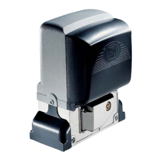
  • Seite 74 Für das besagte Produkt wurden die nachstehenden Bezugsnormen berücksichtigt: siehe Konformitätserklärung. 4 Beschreibung 4.1 Antrieb Dieses Produkt wurde von der CAME CANCELLI AUTOMATICI S.p.A. gemäß den geltenden Sicherheitsvorschriften entwickelt und produziert. Der Antrieb besteht aus einem Alugussgehäuse in dem sich der selbsthemmende Getriebemotor befi ndet und aus einem ABS-Gehäuse in dem sich die elektronische Steuerung, der Transformator und mit Batteriehalterung für zwei Nortbatterien .
  • Seite 75: Beschreibung Der Einzelteile

    4.3 Beschreibung der Einzelteile 1 - Oberer Deckel 2 - Schutzabdeckung der Einstellungsvorrichtung 3 - Halterung für Platine 4 - Stegplättchen Endläufe 5 - Steuerplatine ZD2 6 - Vordere Abdeckung der Steuerung 7 - Abdeckklappe der Entriegelungseinheit 8 - Grundplatte 9 - Befestigungsschraube 10 - Stopper für Befestigungsschrauben 11 - Mutter...
  • Seite 76: Arbeitsgeräte Und Material

    5.2 Arbeitsgeräte und Material Sich davon überzeugen, dass alle Werkzeuge und das notwendige Material zur Durchführung der Installation gemäß den geltenden Sicherheitsvorschriften vorhanden sind. In der nachstehenden Abbildung wird die Mindestausrüstung für den Installateur dargestellt. 5.3 Kabelmindeststärken und typen Kabellänge Kabellänge Kabellänge Anschlüsse...
  • Seite 77: Befestigung Der Grundplatte Und Der Anlage

    5.5 Befestigung der Grundplatte und der Anlage Die folgenden Aufbaumodelle dienen nur als Beispiel, da der Raum für die Anbringung des Antriebes und das Zubehör sich je nach zur Verfügung stehendem Raum unterscheidet. Es ist Aufgabe des Installateurs die beste Lösung auszuwählen. - Am Ende des Tores ein Loch graben (siehe Maße der Zeichnung).
  • Seite 78 - Für Anbringung der Grundlage im Verhältnis zur Zahnstange bitte die in der Zeichnung angegebenen Maße beachten. Den Holzrahmen mit Beton auff üllen und mindestens 24 h fest werden lassen. - Den Holzrahmen entfernen, das Loch um den Betonblock mit Erde auff üllen. - Und die Unterlegscheiben und Muttern entfernen .
  • Seite 79 - Den Deckel der Getriebemotoreinheit durch Aufschrauben der seitlichen Schrauben abnehmen, die Kabelführung mit einem Schraubenzieher oder einer Schere aufbohren und den Getriebemotor auf der Grundplatte anbringen. Achtung! Die Kabel müssen durch die vorgesehenen Kabelführungen gehen. - Den Getriebemotor mit Hilfe der Schraubfüße aus Stahl ca. 5-10 mm hoch anheben, um etwaige spätere Einstellungen zwischen Zahnrad und Zahnstange zu ermöglichen.
  • Seite 80 - Tor von Hand öff nen und schließen und die Kopplungsdistanz zwischen Zahnrad und Zahnstange mit Hilfe der Schraubfüße aus Stahl (vertikale Einstellung) und der Schlitzöff nungen (horizontale Einstellung) einstellen. Dadurch wird verhindert, dass das Torgewicht auf dem Antrieb aufl iegt. Zahnstange Zahnstange Zahnrad...
  • Seite 81: Befestigung Der Endlaufstegplättchen

    5.6 Befestigung der Endlaufstegplättchen Endlaufstegplättchen mit 3mm-Inbussschlüssel an der Zahnstange befestigen. Ihre Position begrenzt den Torlauf. Anmerkung: Vermeiden, dass das Tor beim Auf- und Zulauf gegen die mechanischen Anschläge auff ährt. Mechanischer Anschlag 5.7 manuelle Entriegelung der Getriebemotoreinheit - Dreipassschlüssel ins Schloss stecken, drücken und im Uhrzeigersinn drehen, ..Dreipassschlüssel ..
  • Seite 82: Allgemeine Beschreibung

    6 Steuerplatine 6.1 Allgemeine Beschreibung Die Steuerplatine wird mit 230V AC auf den Klemmen L-N mit einer Frequenz von max. 50/60 Hz gespeist. T EC H NI SC H E DATEN Die Befehls- und Zusatzgeräte werden mit 24V gespeist. Anschluss 230V - 50/60 Hz Achtung! Insgesamt dürfen die Zusatzgeräte nicht mehr als 37 W beanspruchen.
  • Seite 83: Elektrische Verbindungen

    3 4 5 6 7 8 9 10 6.3 Elektrische Verbindungen Getriebemotor, Endlauf und Encoder Beschreibung der schon vorgesehenen elektrischen Verbindungen bei Anbringung links Schwarz Orange Weiß Orange braun blau 24V (d.c.) Motor Mikroschalter Mikroschalter mit Encoder Aufl auf Zulauf Vorzunehmende Änderung der elektrischen Verbindungen bei Anbringung rechts Weiß...
  • Seite 84: Stromversorgung Zubehör

    Stromversorgung Zubehör Masseanschlussöse mit Schraube und Unterlegscheibe Klemmen für elektrischen Anschluss der Zubehörteile: - 24V AC normalerweise; - 24V DC bei Betrieb mit Notbatterien; Zulässige Gesamtleistung: 35W Anschluss 230V (AC), Frequenz 50/60 Hz Warneinrichtungen Warnleuchte (Leistung Kontakt: 24V- 25W max.) - Blinkt während Auf- und Zulauf des Tores.
  • Seite 85: Sicherheitseinrichtungen

    Sicherheitseinrichtungen Lichtschranken DIR Kontakt (N.C.) «Teilstopp» - Eingang für Sicherheitseinrichtungen, wie Lichtschranken, die den Vorschriften nach EN 12978 entsprechen. Unterbrechung der Torbewegung und darauf folgender Autozulauf (wenn diese Funktion ausgewählt wurde). Lichtschranken DIR Kontakt (N.C.) «Wiederaufl auf bei Zulauf» - Eingang für Sicherheitseinrichtungen, wie Lichtschranken, die den Vorschriften nach EN 12978 entsprechen.
  • Seite 86: Elektrische Verbindung Für Sicherheitstest Der Lichtschranken

    DF mit Kontrollsteckkarte der Kontakt (N.C.) di «Wiederaufl auf bei Verbindungen DFI Zulauf» - Eingang für Sicherheitseinrichtungen, wie Sicherheitsleisten, die den Vorschriften nach EN 12978 entsprechen. Bei Zulauf bewirkt der sich öff nende Kontakt die Reversierung der Torbewegung bis zum völligen Aufl auf des Tores;...
  • Seite 87 7 Funktionswahl DIP-SWITCH Setzen nach Default 1 ON - Autozulauf - Der Zeitmesser des Autozulaufs aktiviert sich bei Endlauf im Auflauf. Die vorgegebene Zeit ist einstellbar und hängt in jedem Fall von den Sicherheitseinrichtungen ab. Autozulauf wird nach Notstopp und bei Stromausfall nicht aktiviert. 2 ON - Funktion "auf-stopp-zu-stopp"...
  • Seite 88 9 Signal-Led Led PROG Led PWR Led 1 Led C8 Led 3p Led 7 Led C1 Led C3 Led C7 AUFSTELLUNG DER KONTROLL-LEDS DER BEFEHLSGERÄTE UND SICHERHEITSEINRICHTUNGEN: - «PROG» Rotes Led. Normalerweise aus. Während der Aktivierung des Funkgeräts leuchtet es auf bzw. blinkt es. - «PWR»...
  • Seite 89 10 Programmierung zum Abspeichern der Einstellung Torlauf und Soft-Endlagen Einstellung des Torlaufs – vollständigen Bewegungsablauf (ein Auf- und ein Zulauf) der Anlage durchführen. Die Steuerung speichert den eingestellten Torlauf und die Soft-Endlagen im Auf- und Zulauf automatisch ab. Abspeicherung der Einstellung – Dip 6 auf ON stellen und Taster CH1 drücken bis die Signaldiode an bleibt. Dip wieder auf OFF stellen.
  • Seite 90: Aktivierung Des Funkbefehls

    11 Aktivierung des Funkbefehls Antenne Eventueller Ausgang des zweiten Kanals Antennenkabel RG58 mit den dafür des Funkempfängers (Kontakt N.O.). vorgesehenen Klemmen verbinden. Leistung Kontakt: 5A-24V (DC). Funkmodul Funkmodul auf der Steuerplatine aufstecken ZUVOR STROMVERSORGUNG UNTERBRECHEN (und, wenn vorhanden, Batterien entfernen). N.B.: Die Steuerplatine erkennt das Funkmodul nur dann, wenn sie mit Strom versorgt wird.
  • Seite 91 Speicherung - Den Taster CH1 auf der elektronischen Steckkarte gedrückt halten. Das Led blinkt. Blinkendes LED CH1 = Kanal für Befehle an eine Funktion der Steuerung des Getriebemotors (Befehl „nur auf“ / „auf-zu- reversiere“ bzw. „auf- stopp-zu-stopp“ je nach Wahl auf den Dip- Switches 2 und 3).
  • Seite 92: Sicherheitshinweise

    12 Sicherheitshinweise Wichtige allgemeine Sicherheitshinweise Dieses Produkt muss ausschließlich zu dem Zweck verwendet werden, für den es entwickelt wurde. Andere Verwendungszwecke sind missbräuchlich und gefährlich. Der Hersteller ist nicht für etwaige durch missbräuchliche, fehlerhafte und unangemessene Verwendung verursachte etwaige Schäden verantwortlich. Nicht im Bereich der Scharniere oder der sich bewegenden Teile eingreifen.
  • Seite 93: Wartung

    13 Wartung 13.1 Regelmäßige Wartung Die regelmäßige Wartung durch den Verwender besteht aus: Säuberung der Lichtschranken; Überprüfung der Funktion der Sicherheitsvorrichtungen; Entfernung etwaiger Hindernisse, die den korrekten Betrieb des Antriebs verhindern. Eine regelmäßige Kontrolle der Schmierung und der Halteschrauben des Antriebs ist ratsam. -Um die Sicherheitsvorrichtungen zu überprüfen, während des Zulaufs einen Gegenstand vor den Lichtschranken bewegen.
  • Seite 94: Außerplanmäßige Wartung

    Kontrollbuch in das die vom Verwender durchgeführten regelmäßigen Wartungsmaßnahmen (alle 6 Monate) eingetragen werden. Datum Bemerkungen Unterschrift 13.3 Außerplanmäßige Wartung Die folgende Tabelle dient der Eintragung von außerplanmäßigen wartungsmaßnahmen, Reparationen und Verbesserungen, die von Fachfirmen durchgeführt wurden. N.B. außerplanmäßige wartungsmaßnahmen müssen von Fachleuten durchgeführt werden. Kontrollbuch für außerplanmäßige Wartung Stempel Installateur Name des Fachmanns...
  • Seite 95: Abbruch Und Entsorgung

    CAME CANCELLI AUTOMATICI S.p.A. folgt im Betrieb dem Umweltmanagement gemäß UNI EN ISO 14001 zum Schutz der Umwelt. Wir bitten Sie, diese Umweltschutzarbeit, die für CAME eine Grundlage der Fertigungs- und Marktstrategien sind, durch Beachtung der Entsorgungsangaben weiterzuführen: ENTSORGUNG DER VERPACKUNG Die Bestandteile der Verpackung (Karton, Plastik usw.) können getrennt gesammelt mit dem normalen Hausmüll entsorgt werden.
  • Seite 96 (+34) 91 52 85 009 127273, Moscow Moscow (+34) 91 46 85 442 (+7) 495 739 00 69 (+7) 495 739 00 69 (ext. 226) CAME United Kingdom Ltd. CAME United Kingdom Ltd. GREAT BRITAIN PORTUGAL CAME Portugal CAME Portugal...
  • Seite 97 AUTOMATIZACIÓN PARA CANCELAS CORREDERAS MANUAL DE INSTALACIÓN BX-246 Español...
  • Seite 98: Leyenda De Los Símbolos

    3 Normativas de referencia CAME cancelli automatici es una empresa que cuenta con sistema de gestión de la calidad certificado en ISO 9001:2000 y de gestión ambiental certificado en ISO 14001. CAME proyecta y produce íntegramente en Italia sus productos..
  • Seite 99: Descripción De Las Piezas

    4.3 Descripción de las piezas 1 - Tapa superior 2 - Cárter cubre-válvulas de regulación 3 - Soporte para la tarjeta electrónica 4 - Aletas final de carrera 5 - Tarjeta electrónica ZD2 6 - Tapa anterior del cuadro eléctrico 7 - Puerta de acceso para desbloqueo motorreductor 8 - Placa de fijación...
  • Seite 100: Herramientas Y Materiales

    5.2 Herramientas y materiales Tenga a disposición todas las herramientas y el material necesario para efectuar la instalación de manera segura, respetando las normativas vigentes. En la figura se indican algunos ejemplos de las herramientas que necesita el instalador. 5.3 Tipo de cables y espesores mínimos Longitud cable Longitud cable Longitud cable...
  • Seite 101 5.5 Fijación placa y extensión del grupo Las aplicaciones que siguen a continuación son sólo ejemplos, porqué el espacio para la fijación de la automatización y de los accesorios varía en función de las dimensiones máximas ocupadas y por lo tanto es el instalador quien debe elegir la solución más idónea.
  • Seite 102 Para la colocación de la placa respecto de la cremallera, respetar las medidas indicadas en el dibujo. Llenar el encofrado con cemento y esperar por lo menos 24h hasta que se solidifi que. - Quitar el encofrado, llenar con tierra el foso alrededor del bloque de cemento. - Destornillar las tuercas y las arandelas de los tornillos.
  • Seite 103 - Quitar la tapa del motorreductor destornillando los tornillos laterales, perforar los pasacables con un destornillador o una tijera y colocar el motorreductor sobre la placa. ¡Atención! Los cables eléctricos deben pasar dentro de los pasacables.. - Alzar el motorreductor de la base de fi jación 5÷10 mm operando con los pies roscados de acero para permitir las ulteriores regulaciones eventuales entre piñón y cremallera.
  • Seite 104 - Abrir y cerrar la cancela manualmente y regular la distancia de acoplamiento piñón-cremallera mediante los pies roscados de acero (regulación vertical) y los ojales (regulación horizontal). Esto evita que el peso de la cancela cargue sobre la automatización. Cremallera Cremallera Piñon Piñon...
  • Seite 105 5.6 Fijado aletas final de carrera Colocar las aletas en la cremallera y fi jarlas con llave hexagonal de 3 mm. La posición de éstas delimita la medida de carrera. Nota: evitar que la cancela toque contra el blocheo mecánico, tanto en apertura como en cierre. Bloqueo mecánico 5.7 Desbloqueo manual del motorreductor - Introducir la llave trilobada en la cerradura, empujarla y girarla en sentido horario ..
  • Seite 106 6 Tarjeta electrónica 6.1 Descripción general La tarjeta electrónica se alimenta con 230V AC en los bornes - la sensibilidad de detección del dispositivo amperométrico, L-N, con frecuencia máx 50/60Hz. tanto para la carrera normal como para la desaceleración; Los dispositivos de mando y los accesorios se alimentan con - la velocidad tanto para la carrera normal como para la 24V.
  • Seite 107: Conexiones Eléctricas

    3 4 5 6 7 8 9 10 6.3 Conexiones eléctricas Motorreductor, final de carrera y encoder Descripción de las conexiones eléctricas ya predispuestas para la instalación a la izquierda Negro Anaranjado Rojo Blanco Anaranjado Marron Rojo Azul Motor 24V (d.c.) Microinterruptor Microinterruptor de con Encoder...
  • Seite 108 Alimentación accesorios Terminal de cable de ojal con tornillo y arandela para conexión a tierra Bornes para la alimentación de los accesorios: - a 24V AC normalmente; - a 24V DC cuando intervienen las baterias de emergencia; Potencia total permitida: 35W Alimentación 230V (AC), frecuencia 50/60 Hz Dispositivos de señalación...
  • Seite 109: Dispositivos De Seguridad

    Dispositivos de seguridad Fotocélulas DIR Contacto (N.C.) de «stop parcial» - Entrada para dispositivos de seguridad tipo fotocélulas de conformidad con las normativas EN 12978. Parada de la cancela si está en movimiento y ulterior cierre automático (si la función ha sido seleccionada). Fotocélulas DIR Contacto (N.C.) de «reapertura durante el cierre»...
  • Seite 110 DF con tarjeta de control de las Contacto (N.C.) de «reapertura conecciones DFI durante el cierre» - Entrada para dispositivos de seguridad tipo bordes sensibles, de conformidad con las normativasEN 12978. En fase de cierre de la cancela, la apertura del contacto provoca la inversión del movimiento hasta la completa apertura de la cancela;...
  • Seite 111 7 Selección de las funciones DIP-SWITCH Confi guración de default 1 ON - Cierre automático - El temporizador de cierre automático se activa con final de carrera en apertura. El tiempo preestablecido es regulable y está condicionado de todas maneras, por la eventual intervención de los dispositivos de seguridad y no se activa después de un «stop»...
  • Seite 112 9 Led de señalización Led PROG Led PWR Led 1 Led C8 Led 3p Led 7 Led C1 Led C3 Led C7 LISTA DE SEÑALIZACIÓN DE LOS LED DE CONTROL DE LOS DISPOSITIVOS DE MANDO Y DE SEGURIDAD: - «PROG» Led de color rojo.
  • Seite 113 10 Programación para memorizar el ajuste carrera y las desaceleraciones Efectuar el ajuste de la carrera haciendo cumplir a la automatización una maniobra completa de apertura y una de cierre. La tarjeta electrónica regula automáticamente el ajuste de la carrera con las desaceleraciones de apertura y cierre. Memorizar el ajuste posicionando el dip 6 en ON y apretar la tecla CH1 hasta cuando el led de señalización queda encendido.
  • Seite 114 11 Activación del mando radio Antena Eventual salida del segundo canal del Conectar el cable RG58 de la antena receptor radio (contacto N.O.). en los respectivos bornes.. Portada contacto: 5A-24V (DC). Tarjeta de radiofrecuencia Introducir la tarjeta de radiofrecuencia en la tarjeta electrónica DESPUÉS DE HABER QUITADO LA TENSIÓN (y desconectadas las baterías).
  • Seite 115 Memorización - Tener apretada la tecla “CH1” en la tarjeta electrónica. El led parpadea. LED intermitente CH1 = Canal para mandos dirigidos a una función de la tarjeta del motorreductor (mando “sóolo abre”/”abre- cierra-inversión” o bien “abre-stop-cierra-stop”; en base a la selección efectuada en los dip- switch 2 y 3.
  • Seite 116: Indicaciones De Seguridad

    12 Indicaciones de seguridad Importantes indicaciones generales de seguridad Este producto debe destinarse exclusivamente a la utilización para la cual ha sido específicamente proyectado. Cualquier otro uso debe considerarse inadecuado y por lo tanto peligroso. El fabricante no podrá considerarse responsable debido a eventuales daños causados por usos impropios, erróneos e irracionales.
  • Seite 117: Mantenimiento Periódico

    13 Mantenimiento 13.1 Mantenimiento periódico Las operaciones periódicas a cargo del usuario son: limpieza de las platinas de las fotocélulas; control del correcto funcionamiento de los dispositivos de seguridad; remoción de eventuales obstáculos para el correcto funcionamiento de la automatización. Se aconseja un control periódico de la lubricación y el aflojamiento de los tornillos de fijación de la automatización.
  • Seite 118: Mantenimiento Extraordinario

    Registro de mantenimiento periódico a cargo del usuario(cada 6 meses) Fecha Anotaciones Firma 13.3 Mantenimiento extraordinario La siguiente tabla se utilizará para registrar las operaciones de mantenimiento extraordinario, de reparación y de mejoramiento, efectuados por parte de empresas especializadas externas. Nota: Las operaciones de mantenimiento extraordinario deben ser efectuadas por parte de técnicos especializados.
  • Seite 119: Demolición Y Eliminación

    UNI EN ISO 14001 garantizando el respeto y la tutela del medio ambiente. Invitamos a Ud. a continuar el compromiso por la tutela del ambiente que CAME considera uno de los fundamentos de desarrollo de sus estrategias operativas y de mercado, respetando simplemente breves indicaciones en materia de eliminación:...
  • Seite 120 (+34) 91 52 85 009 127273, Moscow Moscow (+34) 91 46 85 442 (+7) 495 739 00 69 (+7) 495 739 00 69 (ext. 226) CAME United Kingdom Ltd. CAME United Kingdom Ltd. GREAT BRITAIN PORTUGAL CAME Portugal CAME Portugal...
  • Seite 121 AUTOMATISERING VOOR SCHUIFHEKKEN HANDLEIDING VOOR DE INSTALLATIE BX-246 Nederlands...
  • Seite 122: Legenda Van De Symbolen

    Voor intensief gebruik of fl atgebouwen: maximum gewicht van het hek: 600 kg met een maximale lengte van 18 m. 3 Normen waarnaar wordt verwezen CAME cancelli automatici is houder van het ISO- certificaat 9001:2000 voor bedrijfskwaliteitorganisatie en 14001 voor milieubeleid. CAME ontwerpt en produceert geheel in Italië.
  • Seite 123: Controles Vooraf

    4.3 Beschrijving van de delen 1 - Bedekking bovenaan 2 - Carter op afstelinrichtingen 3 - Houder voor printkaart 4 - Eindaanslaghendeltjes 5 - Elektronische printkaart ZD2 6 - Bedekking voorkant stuurkast 7 - Klep op ontgrendelingsysteem aandrijving 8 - Verankeringsplaat 9 - Borgschroef 10 - Aanslag voor bevestigingschroeven 11 - Moer...
  • Seite 124: Standaard Installatie

    5.2 Gereedschap en materialen Zorg voor alle instrumenten en materialen die u nodig hebt voor een veilige installatie volgens alle geldende voorschriften en normen. Op de afbeelding ziet u enkele voorbeelden van gereedschap dat u nodig hebt voor de installatie. 5.3 Kabels, minimum afmetingen Kabellengte Kabellengte...
  • Seite 125 5.5 Grondplaat vastzetten en aandrijving installeren De volgende afbeeldingen vormen slechts een voorbeeld omdat de ruimte voor het monteren van de automatisering en de accessoires kan wijzigen naar gelang van de beschikbare ruimte. De technicus die het systeem installeert, zal dus de meest geschikte oplossing moeten kiezen - Graaf een put bij het verste punt van het hek (zie de tekening voor de maten).
  • Seite 126 Houd rekening met de maten op de tekening om de plaat t.o.v. de tandheugel te plaatsen. Vul de bekisting met cement laat dit minstens 24 uur verharden. - Verwijder de bekisting, vul het gat rondom het cementblok met aarde. - Draai alle moeren, rondsels en schroeven los. De grondplaat moet schoon zijn, perfect waterpas liggen en de schroefdraden voor de schroeven moeten volledig aan de oppervlakte komen.
  • Seite 127 - Verwijder de bedekking van de aandrijving (draai de schroeven op de zijkanten los), maak de kabeldoorgangen open met een schroevendraaier of een schaar en zet de aandrijving op de plaat. Opgelet ! Alle elektrische kabels moeten in de kabeldoorgangen zitten. - Zet de aandrijving 5÷10 mm hoog met de stalen stelpootjes die eronder zitten zodat u later het tandwiel en de tandheugel kunt afstellen.
  • Seite 128 - Open en sluit het hek met de hand en regel de afstand tussen tandheugel en tandwiel met de stalen stelpootjes (in de hoogte) en de stelopeningen (horizontaal). Hiermee voorkomt u dat het gewicht van het hek op de aandrijving rust. Tandheugel Tandheugel Wiel...
  • Seite 129 5.6 Bevestiging hendeltjes voor eindaanslagen Plaats de hendeltjes voor de eindaanslagen op de tandheugel en zet ze vast met een sleutel van 3 mm. De plaats van baanlengte. Opm: laat het hek nooit tot tegen de mechanische stop komen, noch tijdens het sluiten, noch tijdens het openen. Mechanische stop 5.7 Manuele ontgrendeling van de aandrijving - Steek de platte sleutel in het slot, duw de sleutel erin en draai de sleutel naar rechts ..
  • Seite 130: Elektronische Kaart

    6 Elektronische kaart 6.1 Algemene beschrijving De elektronische printkaart werkt op 230V AC op de klemmen - gedeeltelijk openen; L-N met een max. frequentie van 50/60Hz. - de meetgevoeligheid van de spanningmeter zowel voor de De bedieningen en de accessoires werken op 24V. Opgelet ! De normale snelheid als voor de vertraagde beweging;...
  • Seite 131: Elektrische Aansluitingen

    3 4 5 6 7 8 9 10 6.3 Elektrische aansluitingen Aandrijving, eindaanslagen en encoder Beschrijving van de reeds voorziene elektrische aansluitingen voor een links gemonteerde aandrijving Zwart Oranje Rood Oranje bruin Rood blaw Motor 24V (d.c.) Microschakelaar Microschakelaar met Encoder voor open hek voor gesloten hek Wijzigingen aan de elektrische aansluitingen voor een rechts gemonteerde aandrijving...
  • Seite 132 Aansluitstroom accessoires Kabelklem met oogje en schroef en rondsel voor aansluiting op de aarding Stroomaansluitklemmen voor de accessoires: - met 24V AC in normale condities; - met 24V DC als de noodbatterijen werken; Toegestaan totaal vermogen: 35W Aansluitstroom 230V AC frequentie 50/60 Hz Signalisatiemechanismen Knipperlicht waarschuwing voor beweging (Vermogen van het...
  • Seite 133 Veiligheidsmechanismen Fotocellen DIR Contact (N.C.) voor «stop halverwege» - Ingang voor beveiligingen zoals bijvoorbeeld fotocellen, die voldoen aan de voorschriften van de norm EN 12978. Het hek stopt als dit aan het bewegen is en sluit vervolgens automatisch (als deze functie is ingesteld). Fotocellen DIR Contact (N.C.) voor «weer openen tijdens sluiten»...
  • Seite 134 DF met contro- lekaart voor de Contact (N.C.) voor «weer openen tijdens DFI-verbindingen sluiten» - Ingang voor beveiligingen zoals bijvoorbeeld veiligheidsranden die voldoen aan de voorschriften van de norm EN 12978. Tijdens het sluiten van het hek keert de beweging om als dit contact wordt geopend totdat het hek weer helemaal open is;...
  • Seite 135 7 Functies kiezen DIP-SWITCH Defaultinstelling 1 ON - Automatisch sluiten - De timer voor het automatisch sluiten, begint te werken als het hek op de eindaanslag in de open stand komt. De geprogrammeerde tijd kan worden ingesteld en hangt in elk geval af van het in werking treden van de beveiligingen. De timer start niet na een totale «stop»...
  • Seite 136 9 Signaleringslampjes Led PROG Led PWR Led 1 Led C8 Led 3p Led 7 Led C1 Led C3 Led C7 LIJST VAN DE SIGNALERINGEN VAN DE CONTROLELAMPJES VOOR DE BEDIENINGEN EN DE BEVEILIGINGEN: - «PROG» Rood lampje. Normaal uit. Tijdens het inschakelen van de afstandbediening gaat dit lampje aan of knippert het. - «PWR»...
  • Seite 137 10 De banen en vertragingen programmeren en opslaan Laat de automatisering een volledige beweging maken (zowel openen als sluiten) om de baan te programmeren. De baan en de vertragingen tijdens het openen en sluiten worden automatisch opgeslagen op de elektronische printkaart. Sla de geprogrammeerde baan op: zet de dip 6 op ON en druk op de toets CH1 totdat het controlelampje gewoon blijft branden.
  • Seite 138 11 De radiobediening inschakelen Antenne Uitgang van het tweede kanaal van de Sluit de kabel RG58 van de antenne radio-ontvanger (contact N.O.). aan op de bijbehorende klemmen. Vermogen van het contact: 5A-24V (DC). Radiofrequentiekaart Steek de radiofrequentiekaart op de elektronische printkaart ZET EERST DE STROOM UIT (en maak de batterijen los als deze erin zitten).
  • Seite 139 Opslaan - Houd de toets CH1 op de printkaart ingedrukt. Het lampje knippert. LED knippert CH1 = Kanaal voor directe commando’s van een functie op de printkaart van de aandrijving (commando “alleen openen” / “open-sluit-omkeren” of “open-stop-sluit- stop”, afhankelijk van de manier waarop de dip- switches 2 en 3 zijn gezet).
  • Seite 140: Veiligheidsvoorschriften

    12 Veiligheidsvoorschriften Belangrijke veiligheidsvoorschriften van algemene aard Dit product mag alleen worden gebruikt voor de doeleinden waarvoor het door de fabrikant expliciet is bestemd. Elk ander gebruik dient alsoneigenlijk en dus gevaarlijk te worden beschouwd. De fabrikant kan niet aansprakelijk worden gesteld voor eventuele schade die wordt veroorzaakt door oneigenlijk, verkeerd en onverstandig gebruik.
  • Seite 141: Problemen Oplossen

    13 Onderhoud 13.1 Gepland onderhoud Routine-onderhoud ten laste van de gebruiker: de glaasjes op de fotocellen schoonmaken; controleren of de veiligheidsmechanismen goed werken; voorwerpen verwijderen die de bewegingen van het hek kunnen hinderen. Wij raden aan regelmatig de smering te controleren en of de schroeven waarmee het systeem is vastgezet, niet losgekomen zijn. Controleer de beveiligingen op de volgende manier: houd een voorwerp voor de fotocellen tijdens de sluitbeweging.
  • Seite 142 Onderhoudsregister ten laste van de klant (om de 6 maanden invullen) Datum Opmerkingen Handtekening 13.3 Bijzonder onderhoud In de volgende tabel kunt u bilzondere onderhoudswerkzaamheden noteren, reparaties of verbeteringen die door externe, gespecialiseerde bedrijven zijn uitgevoerd. Opm. Elk eenmalig onderhoud moeten worden uitgevoerd door gespecialiseerde technici. Register voor eenmalig onderhoud Stempel van de installateur Naam van de bediener...
  • Seite 143: Conformiteitsverklaring

    UNI EN ISO 14001 ter garantie van een werkwijze die het milieu respecteert. Wij verzoeken u om dit eveneens te doen. CAME is van mening dat milieubehoud een van de steunpilaren is waarop onze bedrijfs- en marktpolitiek rusten door simpelweg enkele eenvoudige afvalvoorschriften na te leven: DE VERPAKKING VERWIJDEREN De verpakkingsmaterialen zoals karton, plastic enz.
  • Seite 144 (+34) 91 52 85 009 127273, Moscow Moscow (+34) 91 46 85 442 (+7) 495 739 00 69 (+7) 495 739 00 69 (ext. 226) CAME United Kingdom Ltd. CAME United Kingdom Ltd. GREAT BRITAIN PORTUGAL CAME Portugal CAME Portugal...
  • Seite 145 AUTOMATIZAÇÕES PARA PORTÕES DE CORRER MANUAL DE INSTALAÇÃO BX-246 Português...
  • Seite 146: Legenda Dos Símbolos

    Para uso constante ou em condomínios: peso máximo do portão 600 kg com comprimento máximo de 18 metros. 3. Referências de normas técnicas Came Cancelli Automatici é uma empresa certificada pelo sistema de gestão da qualidade empresarial ISO 9001:2000 e de gestão ambiental ISO 14001. Came projecta e produz inteiramente em Itália.
  • Seite 147: Descrição De Suas Partes

    4.3 Descrição de suas partes 1 - Tampa superior 2 - Cárter cobre regulagens 3 - Suporte para placa electrónica 4 - Aletas fi m de curso 5 - Placa electrónica ZD2 6 - Tampa dianteira do quadro eléctrico 7 - Portinhola de aceso ao dispositivo de desbloqueio do motorredutor 8 - Coluna de fixação 9 - Parafuso de fixação...
  • Seite 148: Ferramentas E Materiais

    5.2 Ferramentas e materiais Certifique-se de ter todos os instrumentos e o material necessário para efectuar a instalação com a máxima segurança e segundo as normas vigentes. Na figura, alguns exemplos de ferramentas para a instalação. 5.3 Tipos de cabos e espessuras mínimas Tipo de Comprimento de cabo Comprimento de cabo...
  • Seite 149 5.5 Fixação da chapa e assentamento do grupo As ilustrações seguintes são somente exemplos, já que o espaço para a fixação da automatização e dos acessórios varia de acordo com as dimensões de ocupação. Cabe portanto ao instalador a escolha da solução mais adequada. - Escavar um buraco na extremidade do portão (vide cotas do desenho).
  • Seite 150 - Para a colocação da chapa em relação à cremalheira, respeite as medidas do desenho. Encha a ombreira de cimento e aguarde que se solidifi que por 24 horas no mínimo. - Retire a ombreira, encha de terra o buraco em volta do bloco de cimento. - Desatarraxe as porcas e as anilhas dos parafusos.
  • Seite 151 - Retire a tampa do motorredutor a desatarraxar os parafusos laterais Posicione o motorredutor sobre a chapa. Atenção! Os cabos eléctricos devem passar dentro da caixa do motorredutor. - Levante o motorredutor da base de fi xação de 5÷10 mm através dos pés rosqueados de aço, para permitir possíveis regulações futuras entre o pinhão e a cremalheira.
  • Seite 152 - Abra e feche o portão manualmente e afi ne a distância de acoplagem pinhão-cremalheira através dos pezinhos rosqueados de aço (afi nação vertical) e as aberturas oblongas (afi nação horizontal). Isto permite evitar que o peso do portão prejudique a automatização. Cremalheira Cremalheira Pinhão...
  • Seite 153 5.6 Fixação das aletas de fim de curso Posicione as aletas de fi m de curso na cremalheira e fi xe-as com chave hexagonal de 3 mm. Sua posição delimita a medida do curso. Nota:evite que o portão possa bater no bloqueio mecânico, seja na abertura que no fechamento. Bloqueio mecânico 5.7 Desbloqueio manual do motorredutor - Introduza a chave de três lados na fechadura, empurre-a e gire-a no sentido horário.
  • Seite 154 6 Placa electrónica 6.1 Descrição geral A placa electrónica deve ser alimentada a 230V AC nos terminais - abertura parcial; L-N, frequência máx. de 50/60Hz. - a sensibilidade de identifi cação do dispositivo amperimétrico, seja para o curso normal seja para a desaceleração: Os dispositivos de comando e os acessórios são de 24V.
  • Seite 155: Ligações Eléctricas

    3 4 5 6 7 8 9 10 6.3 Ligações eléctricas Motorredutor, fim de curso e encoder Descrição das ligações eléctricas já previstas para a instalação à esquerda Preto Laranja Vermelho Branco Laranja Castanho Vermelho Azul escuro Motorredutor 24V DC Microinterruptor Microinterruptor de com encoder...
  • Seite 156: Dispositivos De Comando

    Alimentação de acessórios Terminal de cabo com anel, parafuso e anilha para ligação à terra. Terminais para a alimentação dos acessórios: - a 24V A.C. normalmente; - a 24V DC quando intervenham as baterias de emergência; Potência total permitida: 35W Alimentação 230V (A.C.), frequência 50/60 Hz Dispositivos de sinalização...
  • Seite 157 Dispositivos de segurança Fotocélulas DIR Contacto (N.C.) de “paragem parcial” - Entrada para dispositivos de segurança tipo fotocélulas, de acordo com as normas EN 12978. Paragem do portão, se em movimento, em seguida o fechamento automático (se a função foi seleccionada). Fotocélulas DIR Contacto (N.C.) de “reabertura durante o fechamento"...
  • Seite 158 DF com placa de controlo das Contacto (N.C.) de “reabertura durante o ligações DFI fechamento" - Entrada para dispositivos de segurança tipo bordas sensíveis de acordo com a norma EN 12978. Na fase de fechamento do portão, a abertura do contacto ocasiona a inversão do movimento até...
  • Seite 159 7 Selecção das funções DIP-SWITCH Programação padrão 1 ON - Fechamento automático - O temporizador do fechamento automático se activa com fim de curso aberto. O período de tempo predefinido pode ser regulado, e está condicionado a possíveis intervenções dos dispositivos de segurança e não se activa depois de um «stop»...
  • Seite 160 9 Lâmpada de sinalização Led PROG Led PWR Led 1 Led C8 Led 3p Led 7 Led C1 Led C3 Led C7 LISTA DAS SINALIZAÇÕES DOS LEDS DE CONTROLO DOS DISPOSITIVOS DE COMANDO E SEGURANÇA: - «PROG» Led de cor vermelho. Normalmente desligado. Durante o procedimento de activação do transmissor, acende-se ou lampeja.
  • Seite 161 10 Programação para memorizar a afinação do curso e das desacelerações. Efectue a afinação do curso, fazendo com que a automatização realize uma manobra completa de abertura e uma de fechamento. A placa electrónica regista automaticamente a afinação do curso com as desacelerações de abertura e fechamento. Memorize a afinação a colocar o dip 6 em ON e prema a tecla CH1 até...
  • Seite 162 11 Activação do comando de rádio Antena Eventual saída do segundo canal do receptor de rádio (contacto N.O.) Ligue o cabo RG58 da antena aos Potência de contacto: 5A-24V (DC). relativos terminais. Placa de rádio frequência Ligue a placa de rádio frequência na placa electrónica DEPOIS DE TER DESLIGADO A TENSÃO (ou desligue as baterias se ligadas). Nota: A placa electrónica reconhece a placa de rádio frequência somente quando é...
  • Seite 163 Memorização - Mantenha premida a tecla CH1 na placa electrónica. O led lampeja. LED intermitente CH1 = Canal para comandos directos com uma função na central electrónica do motorredutor (comando “somente abre” ou “abre-fecha” de acordo com a selecção feita nos dip-switch 2 e 3).
  • Seite 164: Indicações De Segurança

    12 Indicações de segurança Importantes indicações gerais de segurança Este produto deve ser destinado somente para o uso ao qual foi expressamente concebido. Todo e qualquer outro tipo de uso deve ser considerado inadequado e portanto perigoso. O fabricante não pode ser considerado responsável por eventuais danos causados por usos impróprios, erróneos e sem razão.
  • Seite 165: Manutenção Periódica

    13 Manutenção 13,1 Manutenção periódica As intervenções periódicas aos cuidados do utilizador são a limpeza dos vidros das fotocélulas e o controlo do funcionamento correcto dos dispositivos de segurança, e que não existam impedimentos ao funcionamento da automatização. Recomenda-se também o controlo periódico da lubrificação e afrouxamento dos parafusos de fixação da automatização. - Para controlar a eficiência dos dispositivos de segurança, passe um objecto na frente das fotocélulas durante a movimentação na fase de fechamento, se ocorrer a inversão ou o bloqueio da manobra, as fotocélulas funcionam correctamente.
  • Seite 166: Manutenção Extraordinária

    Registo de manutenção periódica aos cuidados do utilizador (a cada 6 meses) Data Anotações Assinatura 13,3 Manutenção extraordinária A tabela seguinte deve ser usada para registar intervenções de manutenção extraordinária, de reparos e de melhorias executadas por empresas externas especializadas. Nota: As intervenções de manutenção extraordinária devem ser efectuadas por técnicos especializados.
  • Seite 167: Eliminação E Desmantelamento

    Ambiental certificado e conforme à norma técnica UNI EN ISO 14001 com garantia do respeito e tutela do meio ambiente. Solicitamos dar continuidade a este trabalho de tutela ambiental, que a CAME considera um dos fundamentos de desenvolvimento das próprias estratégias operativas e de mercado, simplesmente respeitando breves indicações em matéria de eliminação de lixo: ELIMINAÇÃO DA EMBALAGEM...
  • Seite 168 (+34) 91 52 85 009 127273, Moscow Moscow (+34) 91 46 85 442 (+7) 495 739 00 69 (+7) 495 739 00 69 (ext. 226) CAME United Kingdom Ltd. CAME United Kingdom Ltd. GREAT BRITAIN PORTUGAL CAME Portugal CAME Portugal...
  • Seite 169 AUTOMATYCZNE URZĄDZENIE DO BRAM PRZESUWNYCH INSTRUKCJA INSTALACJI BX-246 Polski...
  • Seite 170: Legenda Symboli

    Odnośny produkt jest zgodny z następującymi normami: patrz deklaracja zgodności. 4 Opis 4.1 Mechanizm Produkt ten został zaprojektowany i wykonany przez CAME CANCELLI AUTOMATICI S.p.A. zgodnie z obowiązującymi normami dotyczącymi bezpieczeństwa. Mechanizm składa się z części odlewanej z aluminium, wewnątrz której pracuje elektromechaniczny nieodwracalny motoreduktor, oraz z plastikowej pokrywającej części z ABS, wewnątrz której znajduje się...
  • Seite 171: Opis Części

    4.3 Opis części 1 - Pokrywa górna 2 - Osłona regulacji 3 - Wspornik do karty elektronicznej 4 - Klapki ograniczników 5 - Karta elektroniczna ZD2 6 - Przednia osłona tablicy elektrycznej 7 - Drzwiczki dostępu do odblokowania motoreduktora 8 - Płyta mocująca 9 - Śruba mocująca 10 - Zastawka do śrub mocujących 11 - Nakrętka...
  • Seite 172: Instalacja Standardowa

    5.2 Narzędzia i materiały Upewnić się, że posiada się wszystkie potrzebne narzędzia i materiały do wykonania instalacji, przy maksymalnym bezpieczeństwie i zgodnie z obowiązującymi normami. Poniżej przedstawiono rysunek niektórych przykładów wyposażenia instalatora. 5.3 Typ kabli i minimalne grubości Długość kabla Długość...
  • Seite 173 5.5 Mocowanie płyty i umieszczenie zespołu Poniższe ilustracje są przykładowe, gdyż miejsce do przymocowania mechanizmu i akcesoriów jest różne w zależności od gabarytów. Instalator powienien więc wybrać jak najbardziej dogodne rozwiązanie. - Wykopać dół przy brzegu bramy (patrz wymiary przedstawione na rysunku). Przygotować...
  • Seite 174 - Przy ustawianiu płyty w stosunku do zębatki, przestrzegać wymiarów wskazanych na rysunku. Formę napełnić cementem i poczekać przynajmniej 24 godziny aż się utwardzi. - Wyjąć formę, dół wokół cementu wypełnić ziemią. - Od śrub odkręcić nakrętki i podkładki. Płyta mocująca musi być czysta, dokładnie wypoziomowana, oraz z gwintem śrub całkowicie na powierzchni.
  • Seite 175 - Zdjąć pokrywkę motoreduktora odkręcając boczne śruby. Motoreduktor ułożyć na płycie. Uwaga! Kable elektryczne muszą przechodzić wewnątrz obudowy motoreduktora. - Unieść motoreduktor od podstawy mocującej o 5÷10 mm, poprzez gwintowane stalowe nóżki, aby umożliwić ewentualne następne regulacje między zębnikiem a zębatką. - Poniższe ilustracje dotyczące mocowania zębatki, są...
  • Seite 176 - Ręcznie otworzyć i zamknąć bramę, oraz wyregulować odległość dopasowania zębnika - zębatki, poprzez gwintowane stalowe nóżki (regulacja pionowa), a także poprzez szczeliny (regulacja pozioma). Pozwoli to uniknąć nacisku bramy na mechanizm. Zębatka Zębatka Zębnik Zębnik Nóżki Szczelina Regulacja pozioma Regulacja pionowa Po wykonaniu regulacji, przymocować...
  • Seite 177 5.6 Mocowanie klapek ograniczników Klapki ograniczników umieścić na zębatce i przymocować je kluczem sześciokątnym 3 mm. Ich pozycja ogranicza wymiar skoku. Uwaga: unikać, aby brama uderzała o mechaniczny ogranicznik, zarówno przy otwieraniu jak i zamykaniu. Ogranicznik 5.7 Ręczne odblokowanie motoreduktora - Do zamka włożyć...
  • Seite 178 6 Karta elektroniczna 6.1 Opis ogólny Karta elektroniczna zasilana jest na 230 V AC na zaciskach L-N, z - otwieranie częściowe; częstotliwością max 50/60 Hz. - czułość wykrywania urządzenia amperometrycznego, zarówno dla normalnego skoku, jak i dla spowolnienia; Urządzenia sterujące oraz akcesoria są na 24 V. Uwaga! - prędkość, zarówno dla skoku normalnego, jak i dla Akcesoria nie mogą...
  • Seite 179 3 4 5 6 7 8 9 10 6.3 Połączenia elektryczne Motoreduktor, ogranicznik i enkoder Opis połączeń elektrycznych przewidzianych już do instalacji lewostronnej Czarny Pomarańczowy Czerwony Biały Pomarańczowy brązowy Czerwony niebieski Silnik 24V (d.c.) z Mikrowyłącznik Mikrowyłącznik enkoderem otwarcia zamknięcia Modyfikacje połączeń...
  • Seite 180 Zasilanie i akcesoria Oczkowa końcówka przewodu ze śrubą i podkładką do połączenia uziemienia Zaciski do zasilania akcesoriów: - na 24 V AC normalnie; - na 24 V DC gdy zainterweniują awaryjne baterie; Całkowita dozwolona moc: 35 W Zasilanie 230 V (AC), częstotliwość...
  • Seite 181 Urządzenia bezpieczeństwa Fotokomórki DIR Styk (N.C.) “częściowego stop” - Wejście dla urządzeń bezpieczeństwa, takich jak fotokomórki, zgodnych z normami EN 12978. Zatrzymanie bramy, jeżeli jest w ruchu, oraz następujące automatyczne zamknięcie (jeżeli funkcja została wyselekcjonowana). Fotokomórki DIR Styk (N.C.) “ponownego otwierania w trakcie zamykania” - Wejście dla urządzeń...
  • Seite 182 DF z kartą kontroli połączeń DFI Styk (N.C.) “ponownego otwierania w trakcie zamykania” - Wejście dla urządzeń bezpieczeństwa, takich jak czułe brzegi, zgodnych z normami EN 12978. W fazie zamykania bramy, otwarcie styku powoduje odwrócenie ruchu, aż do kompletnego otwarcia bramy; jeżeli nie jest używane, zewrzeć...
  • Seite 183 7 Selekcja funkcji DIP-SWITCH Nastawienie domyślne/default 1 ON - Automatyczne zamykanie - Czasowy regulator automatycznego zamykania uaktywnia się przy ograniczniku w otwarciu. Ustalony czas jest możliwy do regulacji, który mimo wszystko jest zależny od ewentualnej interwencji urządzeń bezpieczeństwa, oraz który nie uaktywnia się po totalnym “stop” bezpieczeństwa, lub przy braku energii elektrycznej. 2 ON - Funkcja “otwiera-stop-zamyka-stop”...
  • Seite 184 9 LED sygnalizacji Led PROG Led PWR Led 1 Led C8 Led 3p Led 7 Led C1 Led C3 Led C7 WYKAZ SYGNALIZACJI KONTROLNYCH LED URZĄDZEŃ STERUJĄCYCH I URZĄDZEŃ BEZPIECZEŃSTWA: - «PROG» LED w kolorze czerwonym. Zwykle wyłączony. W trakcie procedury aktywacji nadajnika, włącza się na stałe lub miga. - «PWR»...
  • Seite 185 10 Programowanie dla zapamiętania regulacji skoku i spowolnień Wykonać regulację skoku, powodując wykonanie przez mechanizm całkowitego manewru otwarcia i manewru zamknięcia. Karta elektroniczna automatycznie zapisuje nastawienie skoku ze spowolnieniami otwarcia i zamknięcia. Zapamiętać regulację, ustawiając dip 6 na ON i naciskać przycisk CH1 aż do czasu, gdy LED sygnalizacyjny pozostaje włączony. Ponownie nastawić...
  • Seite 186 11 Aktywacja steru radiowego Antena Ewentualne wyjście drugiego kanału odbiornika radiowego (styk N.O.). Kabel RG58 podłączyć do anteny na Obciążenie styku: 5A-24V (DC). odnośnych zaciskach. Karta radioczęstotliwości PO ODŁĄCZENIU NAPIĘCIA (i odłączeniu baterii, jeżeli są podłączone) włożyć kartę radioczęstotliwości do karty elektronicznej. N.B.: Karta elektroniczna rozpoznaje kartę...
  • Seite 187 Zapamiętywanie - Trzymać naciśnięty przycisk CH1 na karcie elektronicznej. LED miga. LED przerywany CH1 = Kanał dla sterów skierowanych do funkcji centralki motoreduktora (ster “tylko otwiera”, lub “otwiera-zamyka”, w zależności od wykonanej selekcji na dip-switch 2 i 3). - Nacisnąć przycisk nadajnika do zapamiętania. LED pozostanie włączony aby zasygnalizować wykonane zapamiętanie. LED włączony Karta radiowa - Wykonać...
  • Seite 188: Wskazówki Dotyczące Bezpieczeństwa

    9 Wskazówki dotyczące bezpieczeństwa Ważne ogólne wskazówki dotyczące bezpieczeństwa Produkt ten powinien być przeznaczony do użycia tylko dla jakiego został wyraźnie stworzony. Wszelkie inne zastosowanie uważa się za niewłaściwe, a zatem niebezpieczne. Konstruktor nie może być odpowiedzialny za ewentualne szkody spowodowane przez niewłaściwe, błędne lub bezmyślne użycie.
  • Seite 189: Konserwacja Okresowa

    13 Konserwacja 13.1 Konserwacja okresowa Okresowe interwencje będące pod odpowiedzialnością użytkownika, to czyszczenie szkiełek fotokomórek i kontrola prawidłowego funkcjonowania urządzeń bezpieczeństwa, oraz aby nie było przeszkód do prawidłowego funkcjonowania mechanizmu. Zaleca się ponadto okresową kontrolę smarowania i prawidłowości dokręcenia śrub mocujących mechanizmu. -Aby skontrolować...
  • Seite 190: Konserwacja Nadzwyczajna

    Rejestr okresowej konserwacji pod odpowiedzialnością użytkownika (co 6 miesięcy) Data Uwagi Podpis 13.3 Konserwacja nadzwyczajna Poniższa tabela służy do rejestracji prac nadzwyczajnej konserwacji, napraw i poprawek, wykonanych przez wyspecjalizowane zakłady zewnętrzne. N.B. Interwencje nadzwyczajnej konserwacji muszą być wykonywane przez wyspecjalizowanych techników. Rejestr konserwacji nadzwyczajnej Pieczątka instalatora Nazwisko operatora...
  • Seite 191 UNI EN ISO 14001, z gwarancją respektowania i ochrony środowiska. Prosimy kontynuować dzieło ochrony środowiska, które CAME uważa za jedną z podstaw rozwoju własnych operatywnych i rynkowych strategii, po prostu poprzez przestrzeganie krótkich wskazówek dotyczących likwidacji urządzenia: LIKWIDACJA OPAKOWANIA Komponenty opakowania (karton, plastik, itd.), są...
  • Seite 192 (+34) 91 52 85 009 127273, Moscow Moscow (+34) 91 46 85 442 (+7) 495 739 00 69 (+7) 495 739 00 69 (ext. 226) CAME United Kingdom Ltd. CAME United Kingdom Ltd. GREAT BRITAIN PORTUGAL CAME Portugal CAME Portugal...
  • Seite 193: Инструкция По Установке

    АВТОМАТИКА ДЛЯ ОТКАТНЫХ ВОРОТ ИНСТРУКЦИЯ ПО УСТАНОВКЕ BX-246 Русский...
  • Seite 194: Условные Обозначения

    Рассматриваемое изделие соответствует требованиям следующих стандартов: смотрите заявление о соответствии. 4. Описание 4.1 Автоматика Это изделие разработано и изготовлено компанией CAME CANCELLI AUTOMATICI S.p.A в полном соответствии с действующими нормами безопасности. Автоматика изготовлена с одной стороны из алюминиевого сплава, защищающего электромеханический нереверсивный привод, с...
  • Seite 195: Описание Компонентов

    4.3 Описание компонентов 1 - Верхняя крышка 2 - Защитная крышка системы регулировок 3 - Кронштейн электронной платы 4 - Концевики с крыльчатой пластиной 5 - Электронная плата ZD2 6 - Передняя крышка электрощита 7 - Дверца для доступа к системе разблокировки...
  • Seite 196 5.2 Инструменты и материалы Перед началом монтажных работ убедитесь в наличии всех необходимых инструментов и материалов, которые позволят произвести установку системы в полном соответствии с действующими нормами безопасности. На рисунке представлен минимальный набор инструментов, необходимых для проведения монтажных работ. 5.3 Типология кабелей и минимальные сечения Длина...
  • Seite 197 5.5 Крепление основания и установка группы Приведенные ниже рисунки носят иллюстративный характер, так как пространство для крепления автоматики и дополнительных устройств может меняться от случая к случаю. Таким образом, выбор наиболее подходящего решения должен осуществляться установщиком на месте. - Подготовьте углубление в грунте у оконечности ворот (смотрите размеры на рисунке). Подготовьте...
  • Seite 198 - В процессе установки монтажного основания необходимо соблюдать расстояния, указанные на рисунке. Заполните опалубку цементным раствором и подождите не менее 24 часов, чтобы он полностью затвердел. - Вытащите опалубку, засыпьте пространство вокруг цементного блока землей. - Отвинтите гайки и снимите шайбы с винтов. Монтажное основание должно быть чистым и абсолютно ровным, резьба винтов должна...
  • Seite 199 - Снимите крышку привода, отвернув боковые винты. Установите привод на монтажное основание. Внимание! Электрические кабели должны входить в корпус привода. - Приподнимите привод над монтажным основанием на 5÷10 мм, используя винтовые ножки из стали, чтобы произвести дальнейшие регулировки между зубчатым колесом и зубчатой рейкой. - Приведенные...
  • Seite 200 - Откройте и закройте ворота вручную и зафиксируйте расстояние в паре "зубчатое колесо - зубчатая рейка" с помощью стальных винтовых ножек (вертикальная регулировка) и отверстий (горизонтальная регулировка). Это позволит избежать излишнего давления массы ворот на автоматику. Зубчатая рейка Зубчатая рейка Зубчатое...
  • Seite 201 5.6 Крепление концевиков с крыльчатыми пластинами Установите концевики с крыльчатыми пластинами на зубчатую рейку и закрепите их с помощью шестигранного ключа 3 мм. Их положение ограничивает ход ворот. Примечание: следите за тем, чтобы ворота не ударялись о механические упоры в процессе открывания и закрывания. Механический...
  • Seite 202: Основные Компоненты

    6. Электронная плата 6.1 Общее описание На электронную плату подается напряжение ~230 В посред- - частичное открывание; ством зажимов L-N, с максимальной частотой 50/60 Гц. - полный стоп. Устройства управления и аксессуары работают от 24 В. Вни- Благодаря соответствующей регулировке можно установить: мание! Суммарная...
  • Seite 203: Электрические Подключения

    3 4 5 6 7 8 9 10 6.3 Электрические подключения Привод, концевик и энкодер Описание электрических подключений, уже предусмотренных для установки слева Оранжевый Черный Красный Красный Оранжевый коричневый Белый синий Привод =24 В с Микровыключатель Микровыключатель энкодером открывания закрывания Изменения...
  • Seite 204 Питание дополнительных устройств Кольцевой кабельный наконечник с винтом и шайбой для заземления Клеммы для питания дополнительных устройств: - ~24 В в стандартных условиях; - =24 В, когда работают аккумуляторы аварийного питания; Макс. допустимая суммарная мощность: 35 Вт Напряжение питания ~230 В, частота...
  • Seite 205 Устройства безопасности Фотоэлементы DIR Контакт (нормально-замкнутый) «частичной остановки» - Вход для устройств безопасности, например, фотоэлементов, соответствующих требованиям стандарта EN 12978. Остановка ворот, если они находятся в движении, с последующим автоматическим закрыванием (если эта функция установлена). Фотоэлементы DIR Контакт (нормально-замкнутый) режима «Повторное открывание...
  • Seite 206 DF с платой управления Контакт (нормально-замкнутый) подключениями DFI режима «Повторное открывание в режиме закрывания» - Вход для устройств безопасности, в частности, чувствительных профилей, соответствующих требованиям стандарта EN 12978. Размыкание контакта во время закрывания створок приводит к изменению направления их движения до...
  • Seite 207 7. Выбор режимов работы и функций DIP-SWITCH Исходные установки 1 ON - Автоматическое закрывание - Таймер автоматического закрывания включается в конце цикла открывания. Предварительно заданное время может быть отрегулировано и зависит от возможного срабатывания устройств безопасности; после полной остановки системы или при отсутствии электроэнергии таймер не включается. 2 ON - Функция...
  • Seite 208: Светодиодные Индикаторы

    9. Светодиодные индикаторы Led PROG Led PWR Led 1 Led C8 Led 3p Led 7 Led C1 Led C3 Led C7 ПЕРЕЧЕНЬ КОНТРОЛЬНЫХ СВЕТОДИОДНЫХ ИНДИКАТОРОВ УСТРОЙСТВ УПРАВЛЕНИЯ И БЕЗОПАСНОСТИ: - «PROG» Красный светодиодный индикатор. Обычно выключен. Загорается или мигает в процессе активирования брелока-передатчика. - «PWR»...
  • Seite 209 10. Программирование настроек движения и замедления Выполните регулировку движения, активировав полный рабочий цикл автоматики: открывание ворот и закрывание. Электронная плата автоматически запоминает регулировку движения ворот с замедлением во время открывания и закрывания. Сохраните регулировку, установив микропереключатель 6 в положение ON и нажимая на кнопку CH1 до тех пор, пока светодиодный...
  • Seite 210 11. Включение радиоуправления Антенна Возможный выход второго радиоканала радиоприемника (нормально- Подключите антенный кабель RG58 разомкнутый контакт) к соответствующим клеммам. Мощность контакта: 5 A, =24 В. Плата радиоприемника ОТКЛЮЧИТЕ ЭЛЕКТРОПИТАНИЕ (или вытащите аккумуляторы, если они используются) и только после этого вставьте плату радиоприемника...
  • Seite 211 Запоминание - Нажмите и удерживайте в данном положении кнопку CH1 на электронной плате. Светодиодный индикатор мигает. Светодиодный индикатор мигает CH1 = Канал для прямого управления одной из функций блока управления привода (команда “только открыть” или “открыть-закрыть”, в зависимости от того, в...
  • Seite 212: Инструкции По Технике Безопасности

    12. Инструкции по технике безопасности Важные инструкции по технике безопасности Это изделие должно использоваться исключительно по назначению. Любое другое применение, не предусмотренное в данной инструкции, рассматривается как опасное. Фирма-изготовитель не несет никакой ответственности за ущерб, нанесенный неправильным использованием системы. Избегайте контакта с направляющими скобами с роликами или другими подвижными механизмами системы во избежание травм.
  • Seite 213: Периодическое Техническое Обслуживание

    13. Техническое обслуживание 13.1 Периодическое техническое обслуживание Пользователем должны периодически выполняться следующие работы: чистка фотоэлементов, контроль за правильной работой устройств безопасности и за отсутствием препятствий для работы автоматики. Кроме того, рекомендуется периодически контролировать состояние смазки и проверять оборудование на наличие воз- можного...
  • Seite 214: Внеплановое Техническое Обслуживание

    Журнал периодического технического обслуживания, заполняемый пользователем (каждые 6 месяцев) Дата Заметки Подпись 13.3 Внеплановое техническое обслуживание Эта таблица необходима для записи внеплановых работ по обслуживанию и ремонту оборудования, выполненных специализированными предприятиями. Важное примечание: ремонт оборудования должен осуществляться профессиональными и квалифицированными специалистами. Журнал...
  • Seite 215: Утилизация Отходов

    __________________________________________________________________________________________________ __________________________________________________________________________________________________ 14. Утилизация отходов В качестве гарантии защиты и охраны окружающей среды компания CAME CANCELLI AUTOMATICI S.p.A внедряет на территории своих учреждений систему управления окружающей средой, сертифицированную и полностью соответствующую международному стандарту UNI EN ISO 14001. Мы убедительно просим вас продолжить начатую работу по защите окружающей среды, лежащую в основе оперативных и...
  • Seite 216 (+34) 91 52 85 009 127273, Moscow Moscow (+34) 91 46 85 442 (+7) 495 739 00 69 (+7) 495 739 00 69 (ext. 226) CAME United Kingdom Ltd. CAME United Kingdom Ltd. GREAT BRITAIN PORTUGAL CAME Portugal CAME Portugal...

Diese Anleitung auch für:

Bx-246

Inhaltsverzeichnis