Herunterladen Inhalt Inhalt Diese Seite drucken
WIKA TC series Betriebsanleitung

WIKA TC series Betriebsanleitung

Widerstandsthermometer und thermoelemente
Inhaltsverzeichnis

Werbung

Verfügbare Sprachen

Verfügbare Sprachen

Resistance thermometers and thermocouples
Widerstandsthermometer und Thermoelemente
Sondes à résistance et thermocouples
Termorresistencias y termopares
Examples/Beispiele/Exemples/Ejemplos
Operating instructions
Betriebsanleitung
Mode d'emploi
Manual de instrucciones
EN
DE
FR
ES

Werbung

Inhaltsverzeichnis
loading

Inhaltszusammenfassung für WIKA TC series

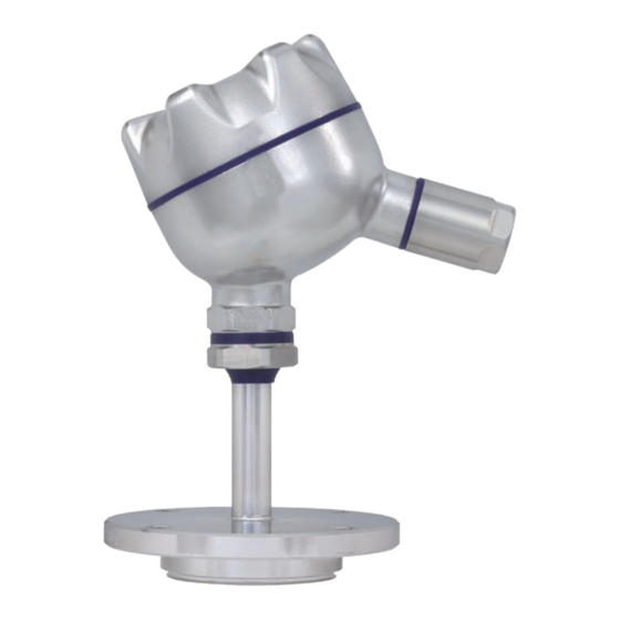
  • Seite 1 Operating instructions Betriebsanleitung Mode d'emploi Manual de instrucciones Resistance thermometers and thermocouples Widerstandsthermometer und Thermoelemente Sondes à résistance et thermocouples Termorresistencias y termopares Examples/Beispiele/Exemples/Ejemplos...
  • Seite 2 Page 35 - 50 Manual de Instrucciones modelos TR y TC Página 51 - 66 © 2010 WIKA Alexander Wiegand SE & Co. KG All rights reserved. / Alle Rechte vorbehalten. WIKA is a registered trademark in various countries. ®...
  • Seite 3: Inhaltsverzeichnis

    Contents Contents 1. General information 2. Safety 3. Specifications 4. Design and function 5. Transport, packaging and storage 6. Commissioning, operation 7. Maintenance and cleaning 8. Faults 9. Dismounting, return and disposal WIKA operating instructions resistance thermometers, thermocouples...
  • Seite 4: General Information

    ... points out useful tips, recommendations and information for efficient and trouble- free operation. DANGER! ...identifies hazards caused by electric power. Should the safety instructions not be observed, there is a risk of serious or fatal injury. WIKA operating instructions resistance thermometers, thermocouples...
  • Seite 5: Safety

    WIKA service engineer. If the instrument is transported from a cold into a warm environment, the formation of condensation may result in the instrument malfunctioning.
  • Seite 6: Special Hazards

    Do not use this instrument in safety or Emergency Stop devices. Incorrect use of the instrument can result in injury. Should a failure occur, aggressive media with extremely high temperature and under high pressure or vacuum may be present at the instrument. WIKA operating instructions resistance thermometers, thermocouples...
  • Seite 7 Made in Germany 2013 Sensor in accordance with standard Year of manufacture F Thin-film resistor ■ W Wire-wound resistor ■ Explanation of symbols Before mounting and commissioning the instrument, make sure you read the operating instructions! WIKA operating instructions resistance thermometers, thermocouples...
  • Seite 8: Specifications

    1) | t | is the value of the temperature in °C without consideration of the sign. Bold: Standard version For further technical information, see WIKA data sheet and the technical information sheet IN 00.17 “Usage limitations and accuracies of platinum resistance thermometers per EN 60751: 2008”.
  • Seite 9: Sensor Types

    400 °C. If the thermocouple is heated further, a transition to a disordered state occurs in the temperature range between approx. 400 °C and 600 °C. Above 600 °C, an ordered crystal lattice is restored. WIKA operating instructions resistance thermometers, thermocouples...
  • Seite 10: Design And Function

    When using a compensating cable or thermocouple cable, an additional measuring error must be considered. For limiting deviations and further specifications, see the corresponding WIKA data sheet and technical information sheet IN 00.23, “Application of thermocouples”. 4. Design and function 4.1 Description...
  • Seite 11: Transport, Packaging And Storage

    (environment, medium) or exceed it, even when taking convection and heat radiation into account! WARNING! Thermometers must be earthed if dangerous voltages could be expected at the connection wires (caused, for example, by mechanical damage, electrostatic discharge or induction)! WIKA operating instructions resistance thermometers, thermocouples...
  • Seite 12: Electrical Connection

    2 x Pt100, 4-wire 2 x Pt100, 2-wire 2 x Pt100, 3-wire white white white black yellow yellow yellow black black white white white white black black black black black yellow yellow yellow yellow WIKA operating instructions resistance thermometers, thermocouples...
  • Seite 13 1 x Pt100 2-wire white 1 x Pt100 3-wire white 1 x Pt100 4-wire white white white 2 x Pt100 2-wire black yellow white 2 x Pt100 black 3-wire black yellow WIKA operating instructions resistance thermometers, thermocouples...
  • Seite 14 Colour code of cable Type of sensor Standard Positive terminal Negative terminal DIN EN 60584 green white DIN EN 60584 black white DIN EN 60584 violet white DIN EN 60584 brown white DIN EN 60584 pink white WIKA operating instructions resistance thermometers, thermocouples...
  • Seite 15: Cable Connections

    As standard, WIKA uses copper profile seals for the connection between the neck tube and the thermowell, and flat paper seals for the connection of the connection head and the extension neck or thermowell.
  • Seite 16: Maintenance And Cleaning

    Residual media in dismounted instruments can result in a risk to personnel, the ■ environment and equipment. Take sufficient precautionary measures. For information on returning the instrument see chapter 9.2 “Return”. WIKA operating instructions resistance thermometers, thermocouples...
  • Seite 17: Faults

    In this case, contact the manufacturer. If a return is needed, please follow the instructions see chapter 9.2 “Return”. WIKA operating instructions resistance thermometers, thermocouples...
  • Seite 18: Dismounting, Return And Disposal

    9.2 Return WARNING! Strictly observe when shipping the instrument: All instruments delivered to WIKA must be free from any kind of hazardous substances (acids, leachate, solutions, etc.). When returning the instrument, use the original packaging or a suitable transport package.
  • Seite 19 Inhalt Inhalt 1. Allgemeines 2. Sicherheit 3. Technische Daten 4. Aufbau und Funktion 5. Transport, Verpackung und Lagerung 6. Inbetriebnahme, Betrieb 7. Wartung und Reinigung 8. Störungen 9. Demontage, Rücksendung und Entsorgung WIKA Betriebsanleitung Widerstandsthermometer, Thermoelemente...
  • Seite 20: Allgemeines

    Information … hebt nützliche Tipps und Empfehlungen sowie Informationen für einen effizienten und störungsfreien Betrieb hervor. GEFAHR! … kennzeichnet Gefährdungen durch elektrischen Strom. Bei Nichtbeachtung der Sicherheitshinweise besteht die Gefahr schwerer oder tödlicher Verletzungen. WIKA Betriebsanleitung Widerstandsthermometer, Thermoelemente...
  • Seite 21: Sicherheit

    Die technischen Spezifikationen in dieser Betriebsanleitung sind einzuhalten. Eine unsachge- mäße Handhabung oder ein Betreiben des Gerätes außerhalb der technischen Spezifikationen macht die sofortige Stilllegung und Überprüfung durch einen autorisierten WIKA-Servicemitarbei- ter erforderlich. Wird das Gerät von einer kalten in eine warme Umgebung transportiert, so kann durch Konden- satbildung eine Störung der Gerätefunktion eintreten.
  • Seite 22: Besondere Gefahren

    Umwelt und Einrichtung führen. Ausreichende Vorsichtsmaßnahmen ergreifen. Dieses Gerät nicht in Sicherheits- oder in Not-Aus-Einrichtungen benutzen. Fehler- hafte Anwendungen des Gerätes können zu Verletzungen führen. Am Gerät können im Fehlerfall aggressive Medien mit extremer Temperatur und unter hohem Druck oder Vakuum anliegen. WIKA Betriebsanleitung Widerstandsthermometer, Thermoelemente...
  • Seite 23: Beschilderung, Sicherheitskennzeichnungen

    1 x Pt100 / A / 3 (F) -50 ... +250 °C Made in Germany 2013 Sensor gemäß Norm Herstellungsjahr F Dünnfilm-Messwiderstand ■ W Drahtgewickelter Messwiderstand ■ Symbolerklärung Vor Montage und Inbetriebnahme des Gerätes unbedingt die Betriebsan- leitung lesen! WIKA Betriebsanleitung Widerstandsthermometer, Thermoelemente...
  • Seite 24: Technische Daten

    1) | t | ist der Zahlenwert der Temperatur in °C ohne Berücksichtigung des Vorzeichens. Fett gedruckt: Standardausführung Weitere technische Daten siehe WIKA-Datenblatt und Technische Information IN 00.17 „Einsatz- grenzen und Genauigkeiten von Platin-Widerstandsthermometern nach EN 60751: 2008“. WIKA Betriebsanleitung Widerstandsthermometer, Thermoelemente...
  • Seite 25: Grünfäule

    400 °C eine geordnete Ausrichtung. Wird das Thermoelement weiter erhitzt, so findet im Temperaturbereich zwischen ca. 400 °C und 600 °C ein Übergang in einen ungeordne- ten Zustand statt. Oberhalb von 600 °C stellt sich wieder ein geordnetes Kristallgitter ein. WIKA Betriebsanleitung Widerstandsthermometer, Thermoelemente...
  • Seite 26: Aufbau Und Funktion

    Bei der Grenzabweichung von Thermopaaren ist eine Vergleichsstellentemperatur von 0 °C zugrunde gelegt. Bei Verwendung einer Ausgleichs- oder Thermoleitung muss eine zusätzliche Messabweichung berücksichtigt werden. Grenzabweichungen und weitere technische Daten siehe entsprechendes WIKA-Datenblatt und Technische Information IN 00.23 „Einsatz von Thermoelementen“. 4. Aufbau und Funktion 4.1 Beschreibung...
  • Seite 27: Transport, Verpackung Und Lagerung

    Messstoff), auch unter Berücksichtigung von Konvektion und Wärmestrahlung nicht unter- oder überschreiten! WARNUNG! Thermometer müssen geerdet sein, wenn an den Anschlussdrähten mit gefährlichen Spannungen zu rechnen ist (hervorgerufen durch z. B. mechanische Beschädigung, elektrostatische Aufladung oder Induktion)! WIKA Betriebsanleitung Widerstandsthermometer, Thermoelemente...
  • Seite 28: Elektrischer Anschluss

    2 x Pt100, 4-Leiter 2 x Pt100, 2-Leiter 2 x Pt100, 3-Leiter weiß weiß weiß gelb gelb schwarz gelb schwarz schwarz weiß weiß weiß weiß schwarz schwarz schwarz schwarz schwarz gelb gelb gelb gelb WIKA Betriebsanleitung Widerstandsthermometer, Thermoelemente...
  • Seite 29 Kabel male am Kabel 1 x Pt100 2-Leiter weiß 1 x Pt100 3-Leiter weiß 1 x Pt100 4-Leiter weiß weiß weiß 2 x Pt100 2-Leiter schwarz gelb weiß 2 x Pt100 schwarz 3-Leiter schwarz gelb WIKA Betriebsanleitung Widerstandsthermometer, Thermoelemente...
  • Seite 30: Sensortyp

    Bei doppelten Thermopaaren werden zwei Thermo-Stecker verwendet. Farbkennzeichnung der Kabel Sensortyp Norm Plus-Pol Minus-Pol DIN EN 60584 grün weiß DIN EN 60584 schwarz weiß DIN EN 60584 violett weiß DIN EN 60584 braun weiß DIN EN 60584 rosa weiß WIKA Betriebsanleitung Widerstandsthermometer, Thermoelemente...
  • Seite 31 Gewinden (z. B. G ½, M20 x 1,5 ...) verbunden werden, müssen diese Gewinde mit Dichtungen gegen den Eintritt von Flüssigkeiten in das Thermometer gesichert werden. WIKA verwendet standardmäßig eine Kupfer-Profildichtung für die Verbindung Halsrohr zum Schutzrohr und eine Papier-Flachdichtung für die Verbindung Anschlusskopf zum Halsrohr oder Schutzrohr.
  • Seite 32: Bezeichnung

    Umwelt vor Gefährdung durch anhaftende Messstoffreste zu schützen. Messstoffreste in ausgebauten Geräten können zur Gefährdung von Personen, ■ Umwelt und Einrichtung führen. Ausreichende Vorsichtsmaßnahmen sind zu ergreifen. Hinweise zur Rücksendung des Gerätes siehe Kapitel 9.2 „Rücksendung“. WIKA Betriebsanleitung Widerstandsthermometer, Thermoelemente...
  • Seite 33: Kalibrierung, Rekalibrierung

    Gerät unverzüglich außer Betrieb zu setzen, sicherzustellen, dass kein Druck bzw. Signal mehr anliegt und gegen versehentliche Inbetriebnahme zu schützen. In diesem Falle Kontakt mit dem Hersteller aufnehmen. Bei notwendiger Rücksendung die Hinweise siehe Kapitel 9.2 „Rücksendung“ beachten. WIKA Betriebsanleitung Widerstandsthermometer, Thermoelemente...
  • Seite 34: Demontage, Rücksendung Und Entsorgung

    Thermometer nur im drucklosen Zustand demontieren! 9.2 Rücksendung WARNUNG! Beim Versand des Gerätes unbedingt beachten: Alle an WIKA gelieferten Geräte müssen frei von Gefahrstoffen (Säuren, Laugen, Lösungen, etc.) sein. Zur Rücksendung des Gerätes die Originalverpackung oder eine geeignete Transportverpackung verwenden.
  • Seite 35 Sommaire Sommaire Généralités Sécurité Caractéristiques techniques Conception et fonction Transport, emballage et stockage Mise en service, exploitation Entretien et nettoyage Dysfonctionnements 10. Démontage, retour et mise au rebut WIKA mode d'emploi sondes à résistance, thermocouples...
  • Seite 36: Généralités

    Les conditions générales de vente mentionnées dans les documents de vente sappliquent. ■ Sous réserve de modifications techniques. ■ Pour obtenir d'autres informations : ■ - Consulter notre site internet : www.wika.fr - Conseiller applications : Tel. : +33 1 343084-84 Fax : +33 1 343084-94 info@wika.fr...
  • Seite 37: Sécurité

    WIKA mode d'emploi sondes à résistance, thermocouples...
  • Seite 38: Dangers Particuliers

    Les applications incorrectes de l'appareil peuvent entraîner des blessures. En cas d'erreur, des fluides agressifs peuvent être disponibles à une température extrême et sous une pression élevée ou sous vide au niveau de l'appareil. WIKA mode d'emploi sondes à résistance, thermocouples...
  • Seite 39 Capteur conforme à la norme Année de fabrication F Résistance à couche mince ■ W Résistance bobinée ■ Explication des symboles Lire impérativement le mode d‘emploi avant le montage et la mise en service de l‘instrument ! WIKA mode d'emploi sondes à résistance, thermocouples...
  • Seite 40: Caractéristiques Techniques

    1) | t | est la valeur de température en °C sans prendre en compte le signe. En gras : version standard Pour de plus amples informations techniques, voir la fiche technique WIKA et la fiche d'informations techniques IN 00.17 “Limitations d'utilisation et précisions des sondes à résistance en platine selon EN 60751: 2008”.
  • Seite 41 400 °C. Si on continue de chauffer le thermocouple, une transition vers un état désordonné se produit dans la plage de température entre environ 400 °C et 600 °C. Au-dessus de 600 °C, un réseau cristallin ordonné est rétabli. WIKA mode d'emploi sondes à résistance, thermocouples...
  • Seite 42: Conception Et Fonction

    En cas d'utilisation d'un câble de compensation ou du câble de thermocouple, une erreur de mesure supplémentaire doit être prise en compte. En ce qui concerne la limitation des écarts et d'autres spécifications, voir la fiche technique WIKA correspondante et la fiche d'informations techniques IN 00.23, “Application des thermocouples”.
  • Seite 43: Transport, Emballage Et Stockage

    La sonde doit être mise à la terre s'il faut s'attendre à des tensions dangereuses au niveau des fils de raccordement (provoquées par exemple par un dommage mécanique, une charge électrostatique ou une induction) ! WIKA mode d'emploi sondes à résistance, thermocouples...
  • Seite 44: Raccordement Électrique

    2 x Pt100, 3 fils rouge blanc rouge rouge blanc blanc jaune jaune noir jaune noir noir rouge rouge rouge rouge rouge blanc blanc blanc blanc noir noir noir noir noir jaune jaune jaune jaune WIKA mode d'emploi sondes à résistance, thermocouples...
  • Seite 45 1 x Pt100 3 fils blanc rouge rouge 1 x Pt100 4 fils blanc blanc rouge blanc 2 x Pt100 2 fils noir jaune rouge rouge blanc 2 x Pt100 noir 3 fils noir jaune WIKA mode d'emploi sondes à résistance, thermocouples...
  • Seite 46 Type de couple Norme Pôle positif Pôle négatif DIN EN 60584 vert blanc DIN EN 60584 noir blanc DIN EN 60584 violet blanc DIN EN 60584 brun blanc DIN EN 60584 rose blanc WIKA mode d'emploi sondes à résistance, thermocouples...
  • Seite 47 être protégés à l'aide des joints afin d'éviter la pénétration de liquides dans la sonde. WIKA utilise en standard un joint profilé en cuivre pour raccorder l'extension au doigt de gant et un joint plat en papier pour relier la tête de raccordement à l’extension ou au doigt de gant.
  • Seite 48: Entretien Et Nettoyage

    Les restes de fluides se trouvant dans des appareils démontés peuvent mettre ■ en danger les personnes, l'environnement ainsi que l'installation. Prendre des mesures de sécurité suffisantes. Indications concernant le retour de l'appareil, voir chapitre 9.2 “Retour”. WIKA mode d'emploi sondes à résistance, thermocouples...
  • Seite 49: Dysfonctionnements

    Contacter dans ce cas le fabricant. S'il est nécessaire de retourner l'appareil au fabricant, respecter les indications mentionnées, voir chapitre 9.2 “Retour”. WIKA mode d'emploi sondes à résistance, thermocouples...
  • Seite 50: Démontage, Retour Et Mise Au Rebut

    AVERTISSEMENT ! En cas d'envoi de l'appareil, il faut respecter impérativement ceci : Tous les appareils livrés à WIKA doivent être exempts de toutes substances dangereuses (acides, solutions alcalines, solutions, etc.). Pour retourner l'appareil, utiliser l'emballage original ou un emballage adapté pour le transport.
  • Seite 51 Contenido Contenido Información general Seguridad Datos técnicos Estructura y función Transporte, embalaje y almacenamiento Puesta en servicio, funcionamiento Mantenimiento y limpieza Fallos 10. Desmontaje, devolución y eliminación de residuos WIKA manual de instrucciones termorresistencias, termopares...
  • Seite 52: Información General

    ... marca consejos y recomendaciones útiles así como informaciones para una utilización eficaz y libre de fallos. ¡PELIGRO! ... indica riesgos causados por corriente eléctrica. Hay un riesgo de lesiones graves o mortales si no se observan estas indicaciones de seguridad. WIKA manual de instrucciones termorresistencias, termopares...
  • Seite 53: Seguridad

    Algunas condiciones de uso específicas requieren conocimientos adicionales, p. ej. acerca de medios agresivos. WIKA manual de instrucciones termorresistencias, termopares...
  • Seite 54 No utilizar este instrumento en sistemas de seguridad o de parada de emergencia. Una utilización incorrecta del instrumento puede causar lesiones. En caso de fallo es posible que haya medios agresivos con temperaturas extremas o bajo presión o que haya un vacío en el instrumento. WIKA manual de instrucciones termorresistencias, termopares...
  • Seite 55 Año de fabricación F Sensor de película delgada ■ W Resistor bobinado ■ Explicación de símbolos ¡Es absolutamente necesario leer el manual de instrucciones antes del montaje y la puesta en servicio del instrumento! WIKA manual de instrucciones termorresistencias, termopares...
  • Seite 56: Datos Técnicos

    1) | t | es el valor numérico de la temperatura en °C sin considerar el signo. En negrita: Ejecución estándar Para más datos técnicos consulte la hoja técnica de WIKA y la información técnica IN 00.17 „Límites de uso y precisiones de termorresistencias de platino conformes a DIN EN 60751: 2008“.
  • Seite 57 400 °C una alineación ordenada. Si se lo sigue calentando, en el rango de temperatura entre aproximadamente 400 °C y 600 °C tiene lugar una transición a un estado desordenado. Por encima de los 600 °C se forma nuevamente una red cristalina ordenada. WIKA manual de instrucciones termorresistencias, termopares...
  • Seite 58: Volumen De Suministro

    Para consultar las desviaciones límite y otros datos técnicos, véase la hoja técnica de WIKA correspondiente y la información técnica IN 00.23 “Uso de termopares”.
  • Seite 59: Transporte, Embalaje Y Almacenamiento

    ¡ADVERTENCIA! ¡En caso de posibles tensiones eléctricas (causados p.ej. por impactos mecánicos, o inducción electrostática!)los hilos de conexión de los termómetros deben estar conectados a tierra. WIKA manual de instrucciones termorresistencias, termopares...
  • Seite 60: Conexión Eléctrica

    2 x Pt100, 3 hilos rojo blanco rojo blanco rojo blanco amarillo negro amarillo amarillo negro negro rojo rojo rojo rojo rojo blanco blanco blanco blanco negro negro negro negro negro amarillo amarillo amarillo amarillo WIKA manual de instrucciones termorresistencias, termopares...
  • Seite 61 1 x Pt100 3 hilos blanco rojo rojo 1 x Pt100 4 hilos blanco blanco rojo blanco 2 x Pt100 2 hilos negro amarillo rojo rojo blanco 2 x Pt100 negro 3 hilos negro amarillo WIKA manual de instrucciones termorresistencias, termopares...
  • Seite 62 Codificación de color de los cables Tipo de sensor Norma Polo positivo Polo negativo DIN EN 60584 verde blanco DIN EN 60584 negro blanco DIN EN 60584 violeta blanco DIN EN 60584 marrón blanco DIN EN 60584 rosado blanco WIKA manual de instrucciones termorresistencias, termopares...
  • Seite 63 La fijación final se realiza con una media rotación de una llave de tuercas. ¡Después del desmontaje hay que sustituir las juntas! Las juntas pueden pedirse a WIKA indicando el número de pedido y/o la referencia (véase la tabla). WIKA manual de instrucciones termorresistencias, termopares...
  • Seite 64: Mantenimiento Y Limpieza

    Restos de medios en instrumentos desmontados pueden crear riesgos para ■ personas, medio ambiente e instalación. Tomar adecuadas medidas de precaución. Véase el capítulo 9.2 “Devolución” para obtener más información acerca de la devolución del instrumento. WIKA manual de instrucciones termorresistencias, termopares...
  • Seite 65: Fallos

    En este caso ponerse en contacto con el fabricante. Si una devolución del instrumento es necesaria, observar las indicaciones en el capítulo 9.2 “Devolución”. WIKA manual de instrucciones termorresistencias, termopares...
  • Seite 66: Desmontaje, Devolución Y Eliminación De Residuos

    ¡ADVERTENCIA! Es imprescindible observar lo siguiente para el envío del instrumento: Todos los instrumentos enviados a WIKA deben estar libres de sustancias peligrosas (ácidos, lejías, soluciones, etc.). Utilizar el embalaje original o un embalaje adecuado para la devolución del instrumento.
  • Seite 67 WIKA operating instructions resistance thermometers, thermocouples...
  • Seite 68 WIKA subsidiaries worldwide can be found online at www.wika.com. WIKA Niederlassungen weltweit finden Sie online unter www.wika.de. La liste des filiales WIKA dans le monde se trouve sur www.wika.fr Sucursales WIKA en todo el mundo puede encontrar en www.wika.es. WIKA Alexander Wiegand SE & Co. KG Alexander-Wiegand-Straße 30...

Diese Anleitung auch für:

Tr10-b

Inhaltsverzeichnis