Hauff-Technik MSH PolySafe MFR/X Montageanweisung
Futterrohr
Inhaltsverzeichnis
Verfügbare Sprachen
Verfügbare Sprachen
Quicklinks
Immer. Sicher. Dicht.
Immer. Sicher. Dicht.
Montageanweisung - MSH PolySafe Futterrohr.
MSH PolySafe MFR/X als erdberührte Wanddurchführung nach DIN
18533-3 mit Dickbeschichtung (PMBC nach DIN EN 15814)
Assembly instruction - MSH PolySafe wall sleeve.
MSH PolySafe MFR/X as ground contact wall entry according to
DIN 18533-3 with thick coating (PMBC according to DIN EN 15814)
Vor Beginn der Montage Anweisung lesen und gut aufbewahren!
Read the instructions prior to installation and keep them in a safe place!
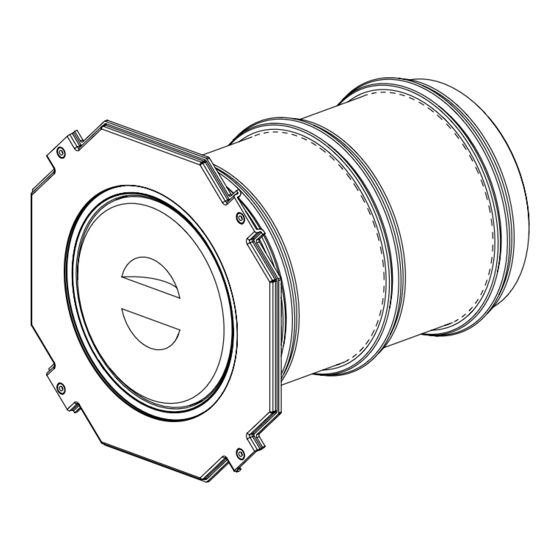
Abb.: MSH PolySafe MFR/X
www.hauff-technik.de
DE
EN
Kapitel
Inhaltsverzeichnis

Verwandte Anleitungen für Hauff-Technik MSH PolySafe MFR/X


Inhaltszusammenfassung für Hauff-Technik MSH PolySafe MFR/X
- Seite 1 18533-3 mit Dickbeschichtung (PMBC nach DIN EN 15814) Assembly instruction - MSH PolySafe wall sleeve. MSH PolySafe MFR/X as ground contact wall entry according to DIN 18533-3 with thick coating (PMBC according to DIN EN 15814) Abb.: MSH PolySafe MFR/X...
-
Seite 2: Inhaltsverzeichnis
6�2 Transportinspektion ����������������������������������������������������������������������� 6 6�3 Lieferumfang ���������������������������������������������������������������������������������� 6 6�4 Lagerung ����������������������������������������������������������������������������������������� 6 Entsorgung�������������������������������������������������������������������������������������������� 7 Beschreibung (z�B� MSH PolySafe MFR/X) ������������������������������������������ 7 Benötigtes Werkzeug und Hilfsmittel ������������������������������������������������ 7 10 Vor der Montage des MSH PolySafe Futterrohrs sind folgende Hinweise zu beachten: ������������������������������������������������������������������������ 8 11 MSH PolySafe Futterrohr montieren ��������������������������������������������������... -
Seite 3: Impressum
MSH PolySafe Futterrohr Impressum Copyright © 2018 by Hauff-Technik GmbH & Co� KG Abteilung: Technische Redaktion Robert-Bosch-Straße 9 89568 Hermaringen, GERMANY Tel. +49 7322 1333-0 +49 7322 1333-999 E-Mail office@hauff-technik.de Internet www.hauff-technik.de Die Vervielfältigung der Montageanleitung - auch auszugsweise - als Nachdruck, Fotokopie, auf elektronischem Datenträger oder irgendein anderers Verfahren bedarf unserer schriftlichen Geneh-... -
Seite 4: Allgemeines Und Verwendungszweck
MSH PolySafe Futterrohr Allgemeines und Verwendungszweck Unsere Produkte sind entsprechend ihrer bestimmungsgemäßen Verwendung ausschließlich für den Einbau in Bauwerke entwickelt, deren Baustoffe dem derzeitigen Stand der Technik entsprechen. Für eine andere oder darüber hinaus gehende Verwendung, sofern sie nach Rücksprache mit uns nicht ausdrücklich schriftlich bestätigt wurde, übernehmen wir keine Haftung. -
Seite 5: 4�3 Tipps Und Empfehlungen
MSH PolySafe Futterrohr GEFAHR! … weist auf eine unmittelbar gefährliche Situation hin, die zum Tod oder zu schweren Verletzungen führt, wenn sie nicht gemieden wird. WARNUNG! … weist auf eine möglicherweise gefährliche Situation hin, die zum Tod oder zu schweren Verletzungen führen kann, wenn sie nicht gemieden wird. VORSICHT! …... -
Seite 6: Transport, Verpackung, Lieferumfang Und Lagerung
MSH PolySafe Futterrohr Transport, Verpackung, Lieferumfang und Lagerung 6�1 Sicherheitshinweise zum Transport HINWEIS! Beschädigungen durch unsachgemäßen Transport! Bei unsachgemäßem Transport können Sachschäden in erheblicher Höhe entstehen. • Beim Abladen der Packstücke bei Anlieferung sowie innerbetrieblichem Transport vorsichtig vorgehen und die Symbole auf der Verpackung beachten. 6�2 Transportinspektion Die Lieferung bei Erhalt unverzüglich auf Vollständigkeit und Transportschäden prüfen. -
Seite 7: Entsorgung
• Elastomere nach den geltenden Umweltvorschriften entsorgen. • Kunststoffe nach den geltenden Umweltvorschriften entsorgen. • Verpackungsmaterial nach den geltenden Umweltvorschriften entsorgen. Beschreibung (z�B� MSH PolySafe MFR/X) Abb.: MSH PolySafe MFR/X Legende zu Abb.: MSH PolySafe MFR/X Anspachtelflansch Verschlusselement (EPP-Element) Verschlussdeckel (PE-Deckel) Futterrohr... -
Seite 8: Vor Der Montage Des Msh Polysafe Futterrohrs Sind Folgende
• Untergrund und Rohrunterbau vor der Rohr-/Kabelverlegung gut verdichten, damit kein Absinken der Rohre/Kabel möglich ist. • Das MSH PolySafe Futterrohr darf nicht mechanisch belastet werden. • Weiteres Zubehör und Informationen unter www.hauff-technik.de und in den technischen Datenblättern. Art. Nr.: 5090033076... -
Seite 9: Msh Polysafe Futterrohr Montieren
MSH PolySafe Futterrohr 11 MSH PolySafe Futterrohr montieren HINWEIS! Keine Abdichtung durch unsachgemäße Montage! Unsachgemäße Montage kann zu Sachschäden führen. • Position und Ausrichtung (3-Ebenen-Einbau oder 2-Ebenen-Einbau) ist grundsätzlich mit den Energieversorgern abzustimmen� • D er Anspachtelfl ansch muss zur Gebäudeaußen- seite ausgerichtet werden, damit dieser ggf. zur Anarbeitung einer PMBC-Dickbeschichtung ver- wendet werden kann. - Seite 10 MSH PolySafe Futterrohr Bei einer Holzschalung wird der Anspachtelfl ansch des Futterrohrs an der Außenschalung angenagelt (siehe Abb.: Legende zu Abb.: 4 Abstand zwischen 3-Stegdichtung und Futterroh- rende mind� 4 cm Abb.: 4 HINWEIS! Mindestabstand nicht eingehalten! Falsche Abstände können zu Sachschäden führen. •...
- Seite 11 MSH PolySafe Futterrohr Danach kann die Schalung geschlossen werden (siehe Abb.: 6). Abb.: 6 HINWEIS! Fehlerhaftes betonieren! Lunkerstellen können zu Sachschäden führen. • Beim Einbetonieren ist darauf zu achten, dass im Bereich des MSH PolySafe Futterrohrs gründlich, lagenweise verdichtet wird. Lunkerstellen müssen vermieden werden.
- Seite 12 MSH PolySafe Futterrohr Das Verschlusselement (EPP-Element) auf der Gebäudeau- ßenseite nach dem Ausschalen umgedreht wieder in das Futterrohr einsetzen (siehe Abb.: 9 und 10). HINWEIS! Keine Abdichtung durch fehlerhafte Anbringung der PMBC-Beschichtung sowie der Perimeter- dämmung! Abb.: 9 Unsachgemäße Montage kann zu Sachschäden führen.
-
Seite 13: Msh Polysafe Montieren
MSH PolySafe Futterrohr 12 MSH PolySafe montieren Futterrohr reinigen (siehe Abb.: 12). Abb.: 12 HINWEIS! Keine Abdichtung durch unsachgemäße Vorbe- reitung der Montage! Unsachgemäß ausgeführte Vorbereitungen können zu Sachschäden führen. • Für die MSH PolySafe-GV1 wird eine saubere und glatte Anlagefl äche benötigt. MSH Mantelrohre, sowie die Dichtlippen des Futterrohrs reichlich mit Gleitmittel einstreichen (siehe Abb.: 13 und 14). - Seite 14 MSH PolySafe Futterrohr Die Einbauposition des Futterrohrs überprüfen und die MSH PolySafe entsprechend dem Futterrohr anpassen/ ausrichten (siehe Abb.: 15 und 16). Die MSH PolySafe wird standardmäßig für den 3-Ebe- nen Einbau ausgeliefert (siehe Abb.: 15). Für den 2-Ebenen Einbau werden Blende und Libelle miteinander getauscht (siehe Abb.: 16).
-
Seite 15: Änderungen Vorbehalten
MSH PolySafe Futterrohr Anschließend die vier Innensechskantschrauben der Abb.: 19 Innenabdichtung kreuzweise anziehen, bis die gelben Druckstifte/Kontrollstifte bündig mit der Frontplatte ab- schließen oder ein Drehmoment von 14 Nm erreicht ist (siehe Abb.: 19 und 20). Legende zu Abb.: 20 Gelber Druckstift/Kontrollstift Abb.: 20 Abschließend können Schutzrohre gas- und wasserdicht... - Seite 30 Notizen / Notes Art. Nr.: 5090033076 Rev.: 00/2018-05-07...
- Seite 31 Notizen / Notes Art. Nr.: 5090033076 Rev.: 00/2018-05-07...
- Seite 32 Hauff-Technik GmbH & Co. KG Robert-Bosch-Straße 9 89568 Hermaringen, GERMANY Tel. +49 7322 1333-0 Fax +49 7322 1333-999 office @ hauff-technik.de www.hauff-technik.de...